The Smyrna Special
The Smyrna Special is a simple, beginner level, rubber powered, free flight airplane with good flight performance. A plan prepared by Jim Bair for Dale Whitford’s group in Kettering, Ohio, may be found here: Smyrna Special I 2 sheets . Download and print the file, it prints on two 8 1/2″ x 11″ sheets. Use a straight edge and razor blade to cut one of the sheets along the “Cut Line”. Place that sheet over the other one and align the cut edge of the first with the “Cut Line” of the other and glue or tape them together. You can use this as a master copy to print more on 11″ x 17″ paper. Jim has this to say about the plane:
“I was involved in a kid’s building and flying class for several years. Our beginners were as young as third graders.The first airplane we had them build was the Smyrna Special. It is a dependable, moderately rugged, good flyer. Our flying was in a church gym so the trim-able rudder was needed.
With the Smyrna Special (and other simple models) we used the red 5 1/2 inch props when we could get enough and the black 6 inch props when we had to. The prop shaft wire on the black ones was too soft and bent too easily. Don’t try to optimize for best performance. The purpose is to get kids (or anyone for that matter) started with a dependable decent flying airplane. If it is built well, CG location will be close right off the board and it will fly a fairly tight circle without spiraling in. If it’s not built well (expect that with beginners) it will be harder to trim. A little clay on the nose will take care of the CG. The real problem is keeping the wing up on the inside of the power circle. We were flying in a small gym so we had to keep the circle fairly small. That’s the reason for the adjustable rudder but it’s a good feature to have anyway. We used wing tip weight, tabs and Gurney flaps in various combinations. Some of the building jobs were really poor but I don’t think we ever had one we couldn’t get reasonable flights with. We did have to fly right circles with a few that we just couldn’t get to fly a left circle.”
This plane was originally developed for use in Tim Lavender’s kids model airplane program in Smyrna, Tennessee. You can see examples of it in this video.
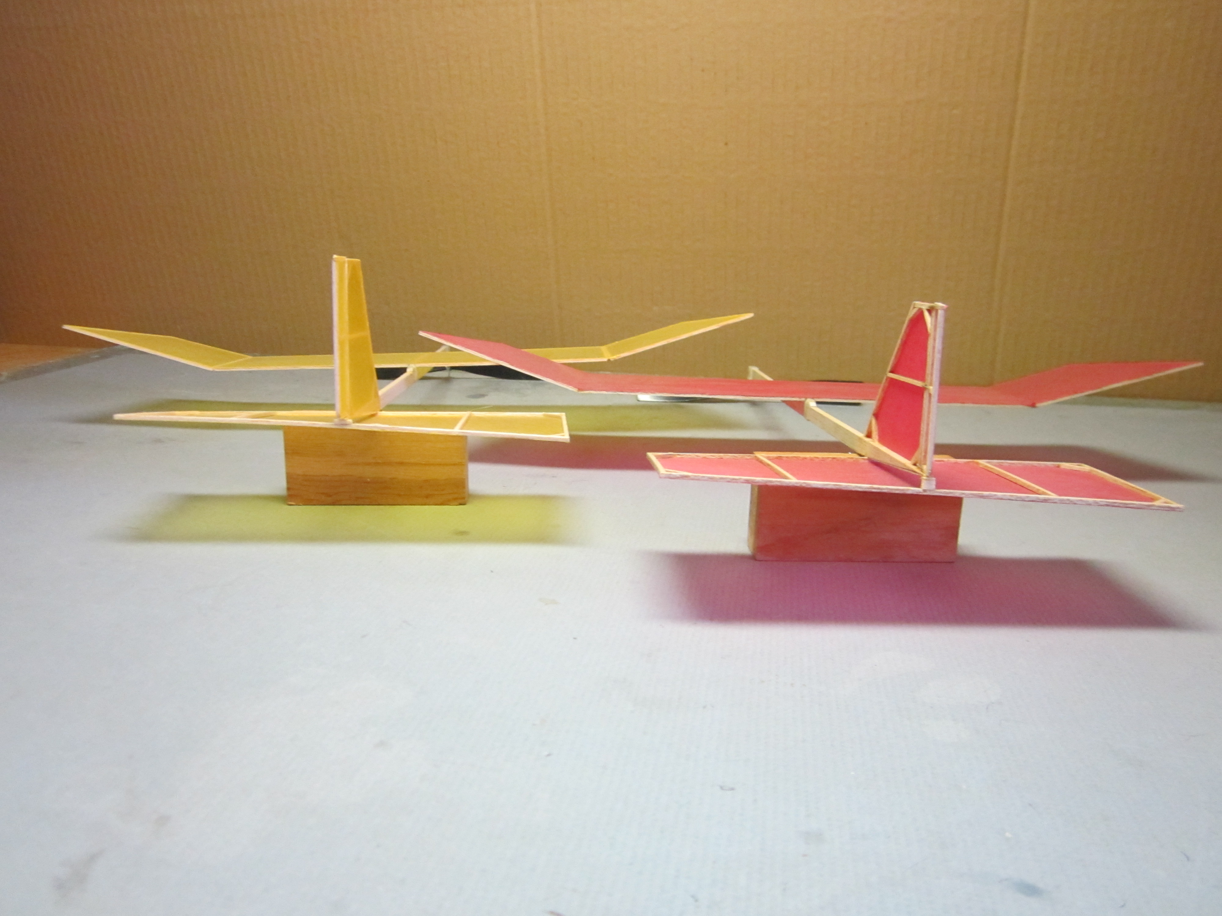
The Smyrna Special II
I saw some opportunities to simplify and lighten the plane, as well as make the wing position adjustable for flight trim without having to add clay weight to adjust the balance.
These are my changes, from nose to tail. I call this the Smyrna Special II.
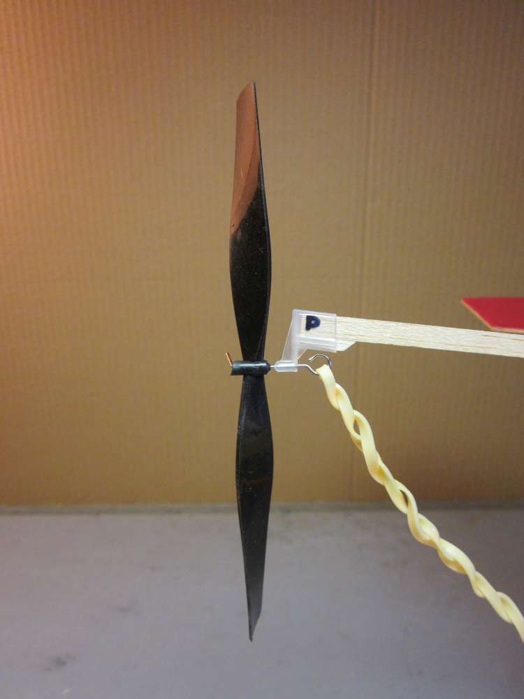
1.0 The wing area of 41.43 square inches is asking for a 6″ diameter propeller. (A good minimum diameter for a free flight rubber propeller is the square root of the wing area.) I chose to go with the 6″ black plastic prop assembly. Others have noticed problems with the shaft provided on the similar 6″ prop assemblies purchased from Midwest. They bend easily and sometimes the shaft has acquired a curve in bending over the end which interferes with freewheeling. Check that the shaft is straight inside the prop hub. You can replace the prop shaft with one made from 0.039″ steel wire (K&S 0.047″ music wire or piano wire) or buy replacement shafts from one of our suppliers. You can get both 6″ silver plastic props and prop shafts from Peck-Polymers. Check the balance of the prop and scrape the back of the heavy blade to get it to balance. Put a tiny bit of light machine oil on the bearing surfaces.
2.0 I replaced the 1/8″ x 3/8″ x 14 3/8″ stick with one that is 1/4″ deep. This is considerably lighter than the original 3/8″ stick and sufficiently strong to do its job. Use medium weigh balsa for this. Put the heavy end of the stick to the front.
3.0 The stick is now not a snug fit in the prop box, so a 1/2″ length of 1/8″ square is glued to the underside of the fuselage stick. Use medium weigh balsa for this. It must be tough to withstand the shock of the propeller hitting the ground.
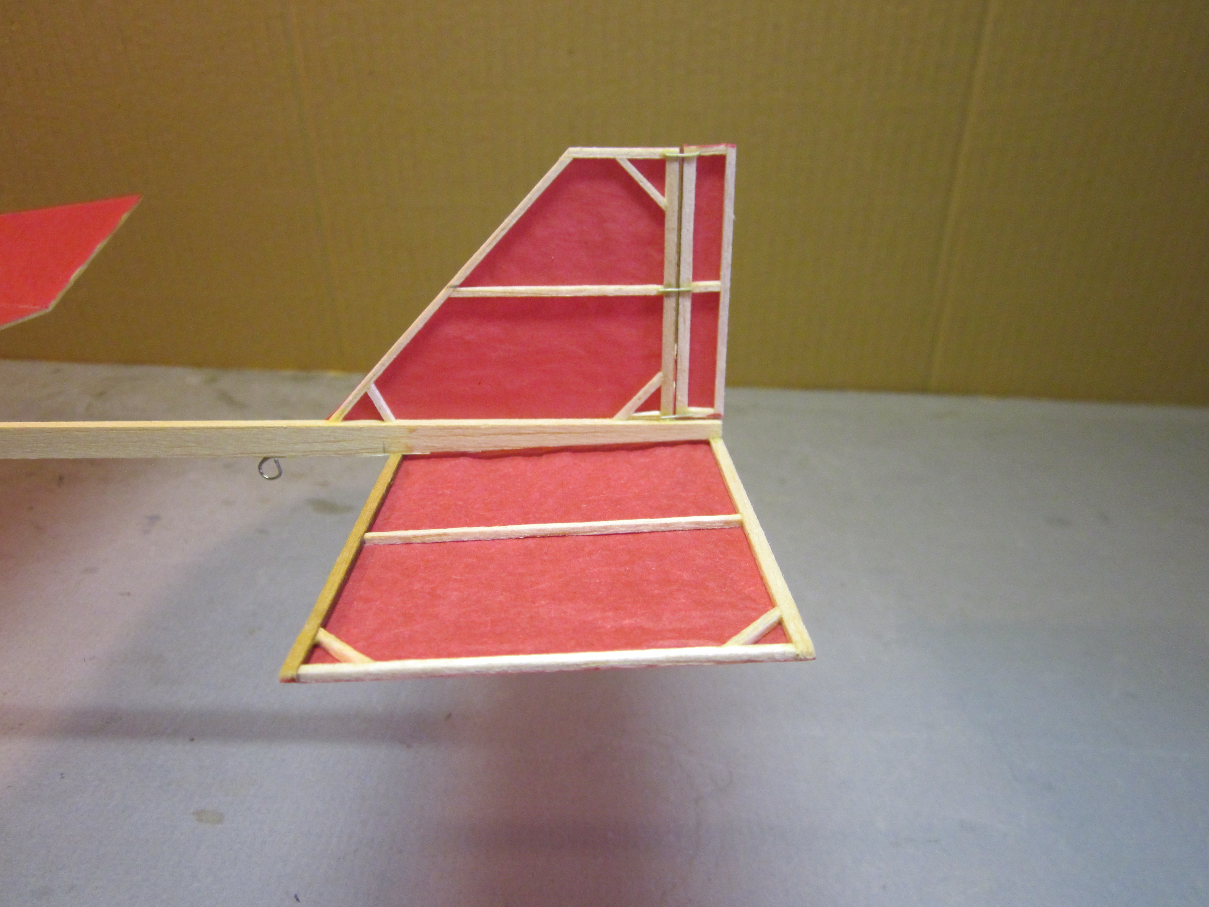
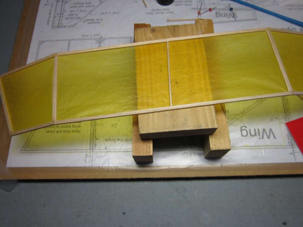
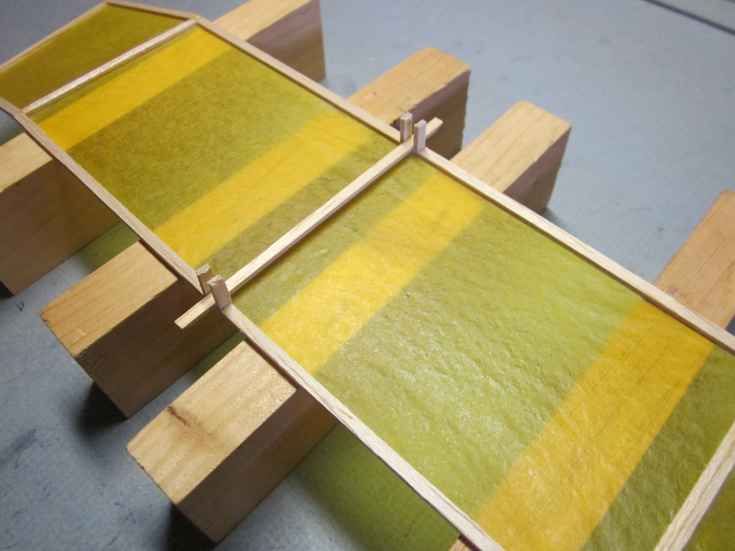
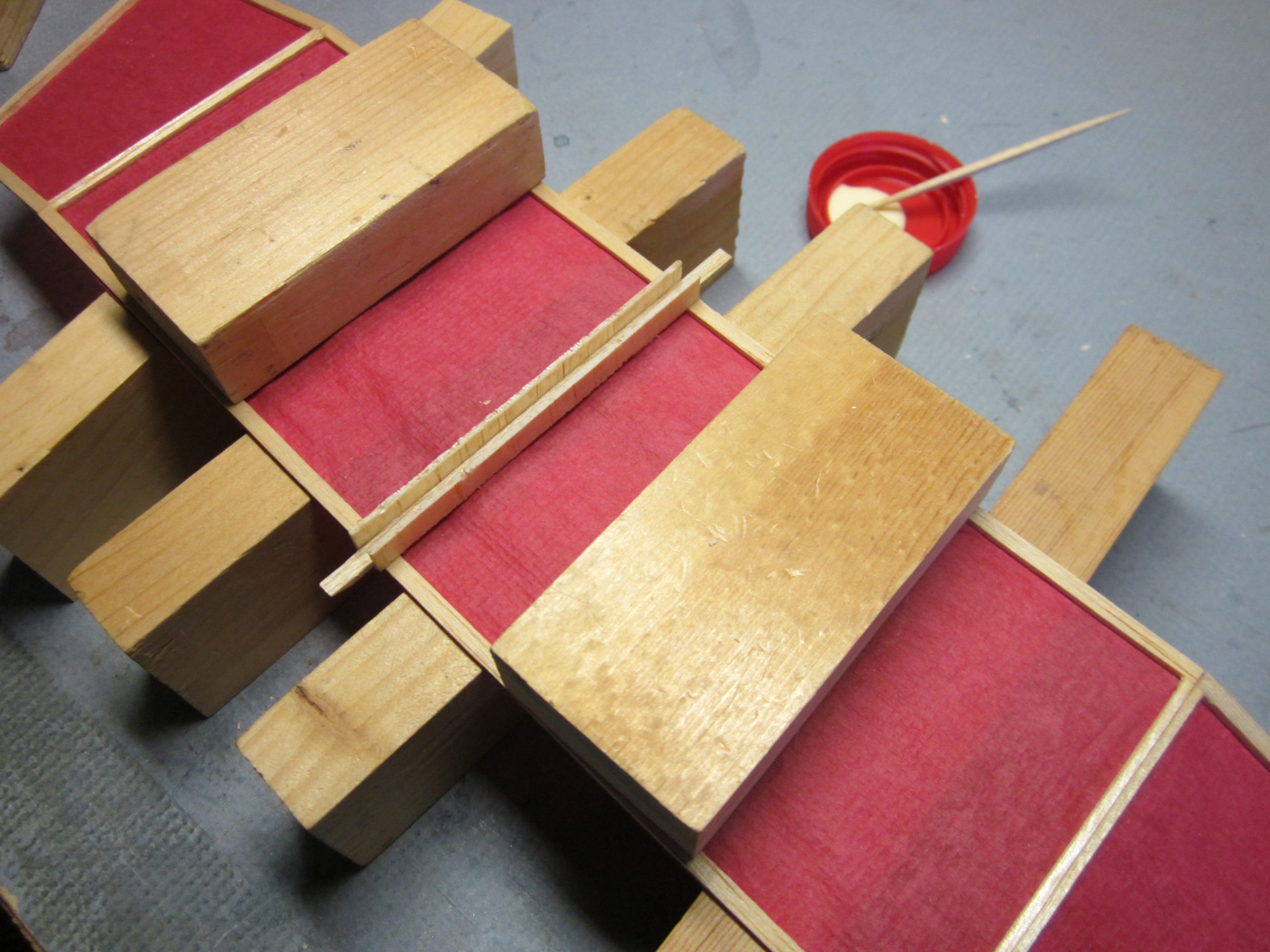
 (Picture shows wing upside down.)
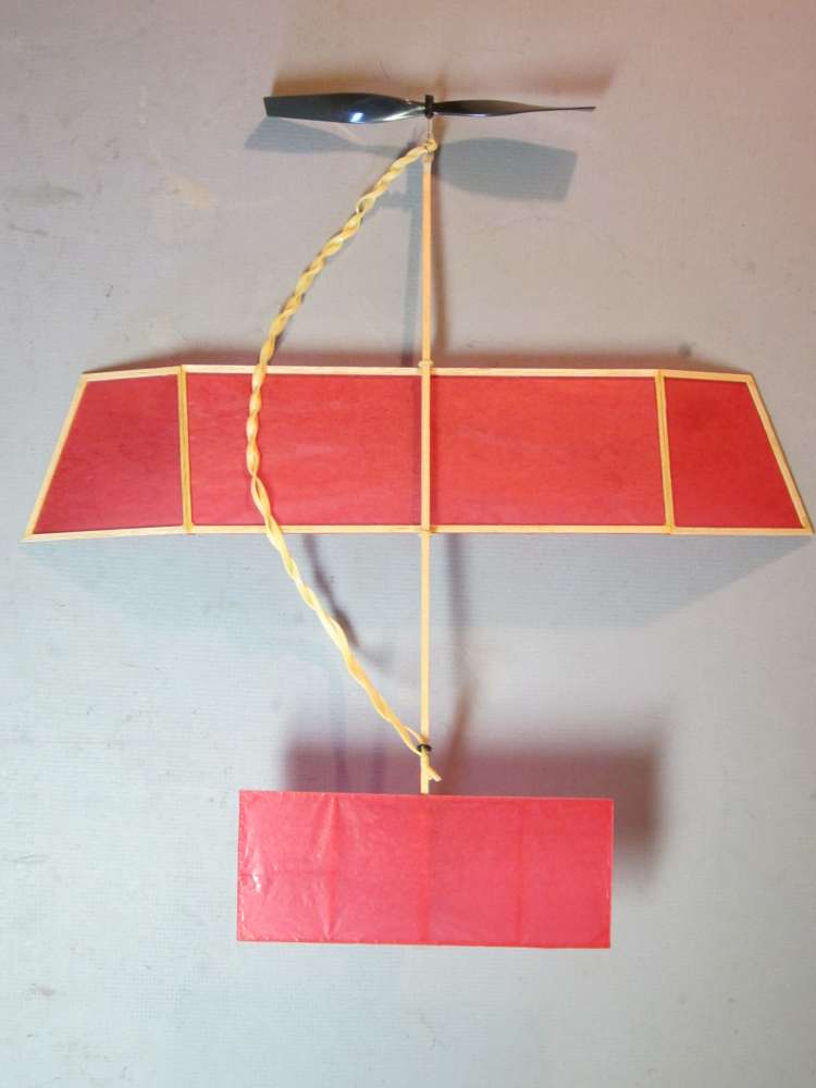
4. I eliminated the wing pylon entirely, again saving considerable weight, and a lot of cutting, sanding and gluing. Also, such pylons unnecessarily complicate trimming these little planes. Pylons may make sense in high power gas models, for reasons that are specific to high power, steep climbs. The Smyrna Special II will be flown indoors, where a ceiling height limits the power, or outdoors in a way that does not favor high power. Having the wing on a pylon produces a strong up pitch in the initial power burst. The propeller thrust is offset well below the wing resistance, producing a strong up pitch moment. This must be balanced by adding clay weight to the nose or setting the tailplane for down pitch. When the power burst burns off, those down pitch moments dominate, causing a dive or at least a steep descent in the glide. With the wing down on the stick, it is possible to get good longitudinal trim at all power settings.
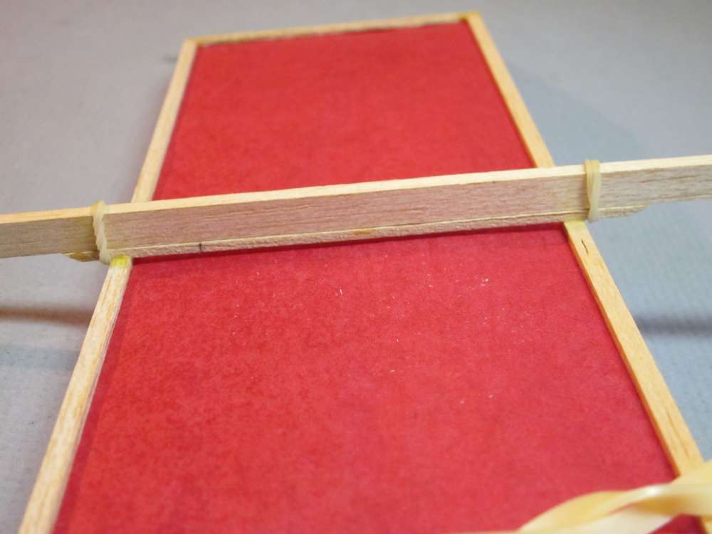
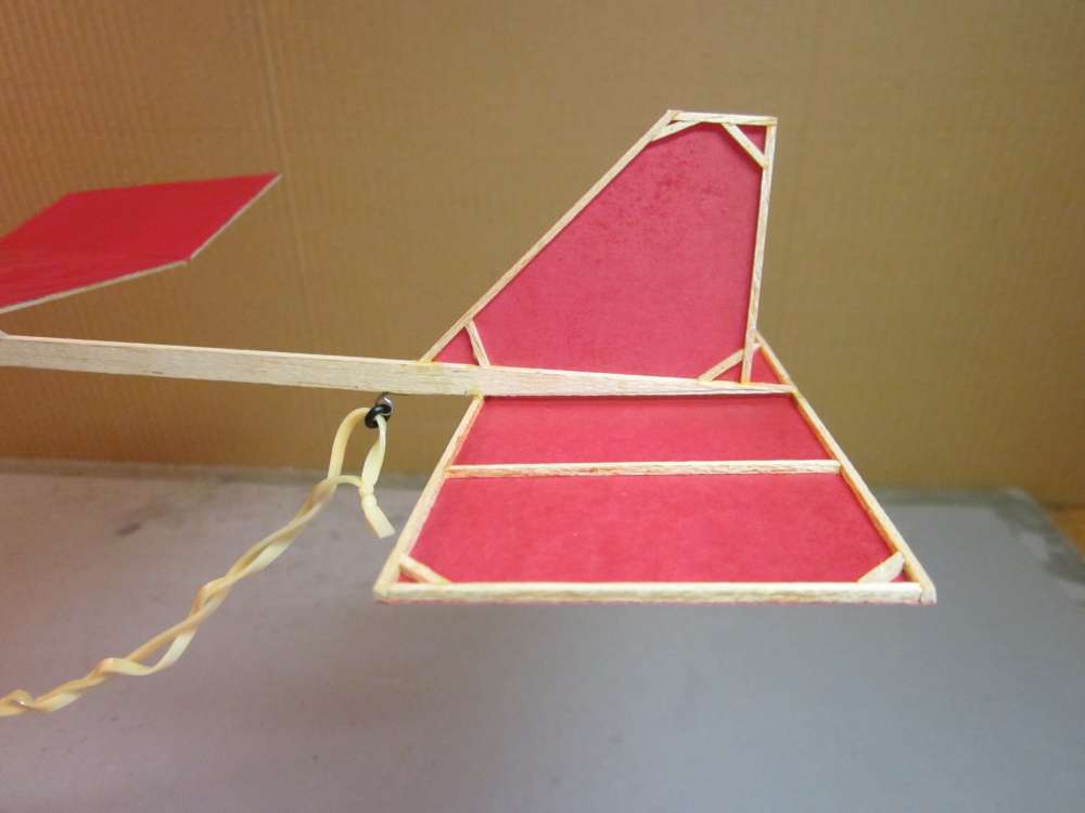
5. I used a 1/16″ x 1/8″ x 3 3/4″ hold down stick with a couple stout dental rubber bands to hold the wing to the stick. These can be doubled over to make them tighter, if necessary. They should be tight enough to keep the wing from wobbling. Later I found that the wing would wobble when flown outdoors in even slight wind, making it difficult to get reliable launches. I fixed this by adding saddle pieces to the hold down stick. See the builder notes, below. This type of wing has best sink speed at about 8 degrees attack angle, measured from the zero lift line. The drag of the fuselage assembly would favor a slightly higher attack angle. The zero lift line on this type of airfoil approximately corresponds to the line through the bottom of the trailing edge and the top of the leading edge, in this case about 1.2 degrees. The prop bearing has about 7 1/2 degrees of down thrust, so the attack angle will be about 8.7 degrees. Given the rough nature of our design assumptions, this looks pretty good. No shims are necessary.
6. The hold down stick makes the center rib unnecessary, so I left it out. This lightens the wing a bit.
7. I eliminated the long diagonal ribs as unnecessary.
8. I replaced the two 1/8″ dihedral ribs with two 1/16″ ribs. These were sanded to a bevel to make a strong dihedral joint. The thin ribs must be backed with wider pieces of wood when sanding to keep the center of the rib from bowing away from the sandpaper. (See below.) The method of sanding dihedral bevel is described elsewhere on this site, about 2/3 down the page. Here we will use flat boards, rather than cambered boards. Keep the same 1″ dihedral under each tip.
9. The ribs are canted 1/16″ to give washout (increased incidence) on the left wingtip and washin (decreased incidence) on the right wing tip. This produces a right rolling moment which balances the left rolling moment of the motor. Rolling moment produced in this way is dependent on the speed of the plane, and thus the thrust and torque, so the rolling moment will vary roughly in proportion to the motor torque which it is intended to counter. Other methods, such as adding clay weight to one wing tip or offsetting the wing, will produce a constant rolling moment that will balance at only one torque value. With rubber motors, we must accommodate a wide range of torques. (Peak torque may be five times the average torque.)
To accomplish this, the right leading and left trailing dihedral break points are 4 11/32″ from the wing center line and the left leading and right trailing dihedral break points are 4 9/32″ from the wing center line. The 1/16″ square dihedral ribs go on either side of the respective break lines. Draw these lines on your drawing, extending them past the leading and trailing edges so you can see them when the sticks are pinned to the plan.
10. I used a right handed pigtail motor hook, described elsewhere on this site. Wound motors are less likely to twist off a right handed pigtail, which they will do from a straight pin hook. This hook also keeps the motor spaced away from the stick so the knots in the motor do not rub on the stick.
11. I moved the motor hook as far back as practical, to fit the longest possible motor. A longer motor means more turns which means more time in the air. One danger here is the proximity to the fragile tailplane, which is easy to bump while struggling to get a tightly wound, lubricated motor onto the hook. I use an O-ring to make this easier. With clumsy kids, you might want to move it a bit more forward.
12. The fin gussets are made from 1/16″ square stock, for a very slight weight saving, but weight eliminated from the extreme back of the plane eliminates the need to add many times more clay weight at the nose for balance.
13. The fin is built on the right side of the stick, per plan, and papered on the right surface only. This construction makes the fin have a slight left turning moment. I decided that this would be sufficient and the rudder would not be necessary. I found that the plane wants to fly perfectly straight with moderate to low torque. Perhaps a little less twist could be put in the wing, or a rudder could be used. A final decision will be made when more experience flying is gained. (See below. I added a rudder.)
14. The motor stick is tapered over the 2 5/8″ tailplane chord from full 1/4″ depth to zero at the back end. This in combination with putting the tissue on the bottom of the tailplane gets me close to the incidence I want on the tail. The cutting and sanding of tailplane taper is described elsewhere on this site about 1/3 down the page. I find that the plane likes to stall, so I may reduce the angle of the tailplane taper. (As indeed I did, see below. The taper now ends with 1/8″ depth at the back end of the stick.)
15. The center tailplane rib is omitted because the fuselage stick will perform the function when assembled.
16. The tailplane gussets are 1/16″ square, as on the fin.
17. The tailplane is covered on the bottom surface to give the negative incidence I want. I want the zero lift line of the tailplane to be parallel with he propeller axis. The zero lift line is at about 1.36 degrees to the face. This, in combination with the 5.44 degree taper, puts the tailplane incidence to minus 6.80 degrees, not quite the 7.5 degrees we want. The downwash from the wing will add to the effective negative incidence of the tailplane, but the downwash is unknown. It is probably more than the 0.7 degree deficiency, so we are “close enough”. The final longitudinal trim will be established with the wing position. (Later I changed the tailplane taper. See below.)
18. For test flying, I grabbed a handy 15″ loop of 1/8″ rubber. The plane flys pretty well with this motor. I suspect that thinner rubber will work better. The distance between the hooks is 10 1/2″. My rule of thumb is to use a motor twice that in length. The finished airplane weighs 9.45 grams. My motor sizing formula says this will fly best with a 21″ loop of 0.080″ rubber. Unless you have a rubber stripper, you would do as well with a 21″ loop of standard 3/32″ rubber, as a start. A motor this long will require stretch winding with a winder and stooge. Rubber motors should always be lubricated.
I gradually increased the number of turns put into the motor in increments of 100. It flew pretty well with 1,000 turns on this motor, out of a possible 1,500, and the wing set so it balances 4 3/16″ from the nose, 0.55″ behind the leading edge of the wing. It climbed steeply for about a 1/4 turn, stalled slightly, then set off straight across the park. I added a 1/4″ paper tab to the fin, bent slightly for a left turn and I got a consistent, slightly tight, left turn. I am considering several more permanent fixes: overall larger fin; adjustable rudder; making the fin a separate unit and gluing it to the stick with a slight left turn angle.
Test Flights – We Learn From Experience
Windy and rainy weather has prevented opportunities for much test flying. I started with short tests in the street in front of the house. It climbed steeply in left circles with a slight stalling tendency on initial torque. Then it would straighten out and fly straight across the neighborhood. I had three recoveries from trees and two from rooftops. This showed me that it does not want to fly in left circles when the power goes down. I thought maybe a larger fin would produce more left turning tendency, but that did not work. I thought maybe the wing twist was preventing the left circle, so I made another wing with no washin or washout. That did not work, the plane now banked steeply left in the climb. Adding a sheet balsa rudder offset about 1/16″ to the left did make it turn left in the descent. I made two stick and tissue rudders, one for the original fin and a larger one for the larger fin. They are full span and 3/8″ wide. These are hinged to the fins with stiff iron wire.
I also decided to adjust the tailplane incidence by adding a 1/16″ shim under the trailing edge of the plane with the larger fin. This seemed to help with the stalling tendency. The tailplane incidence was a rough guess. I ignored downwash. The wing produces lift by deflecting air downward. The tailplane operates in this downwardly deflected air. I decided to make a rough estimate of the downwash angle and set the tailplane incidence accordingly. Frank Zaic, in Circular Airflow, page 16, gives a rough formula for downwash for tailplanes 2 to 4 wing chords behind the wing and within 1/2 chord above or below the wing. The downwash is 5.25 times the lift coefficient plus 0.25. Published wing tests show lift coefficients of 0.557 and 0.569 for flat plates at minimum sink. These tests were run at Reynolds numbers a bit higher than our wing will experience, but our wing has a bit of camber. Ours could be higher or lower than these values. The Wright No. 9 airfoil is a 5% arc with lift coefficient 1.07 at minimum sink. Our wing has about 2% camber. This test is at a Reynolds number somewhat higher than our plane will experience. I am confident that our wing will not have a lift coefficient that high. It will likely be closer to 0.6. That 0.6 implies a downwash angle of 3.40 degrees. This may not be exactly right, but it is better than ignoring downwash altogether. We want the tailplane to align with the flow of air produced by the propeller pulling the plane forward. We start with the tailplane zero lift line aligned with the prop shaft with a -7.50 incidence. We raise it 3.40 degrees to accommodate the downwash. We add another 1.36 degrees from the zero lift line to the flat chord. This results in an incidence of -2.74 degrees, corresponding to a deflection of almost exactly 1/8″ over the 2 5/8″ chord of the tailplane. I added a 1/8″ shim under the trailing edge of the tailplane. It would be best to taper the 1/4″ stick to a 1/8″ depth at the back end. The taper to zero thickness is a weak spot that I am glad to avoid.
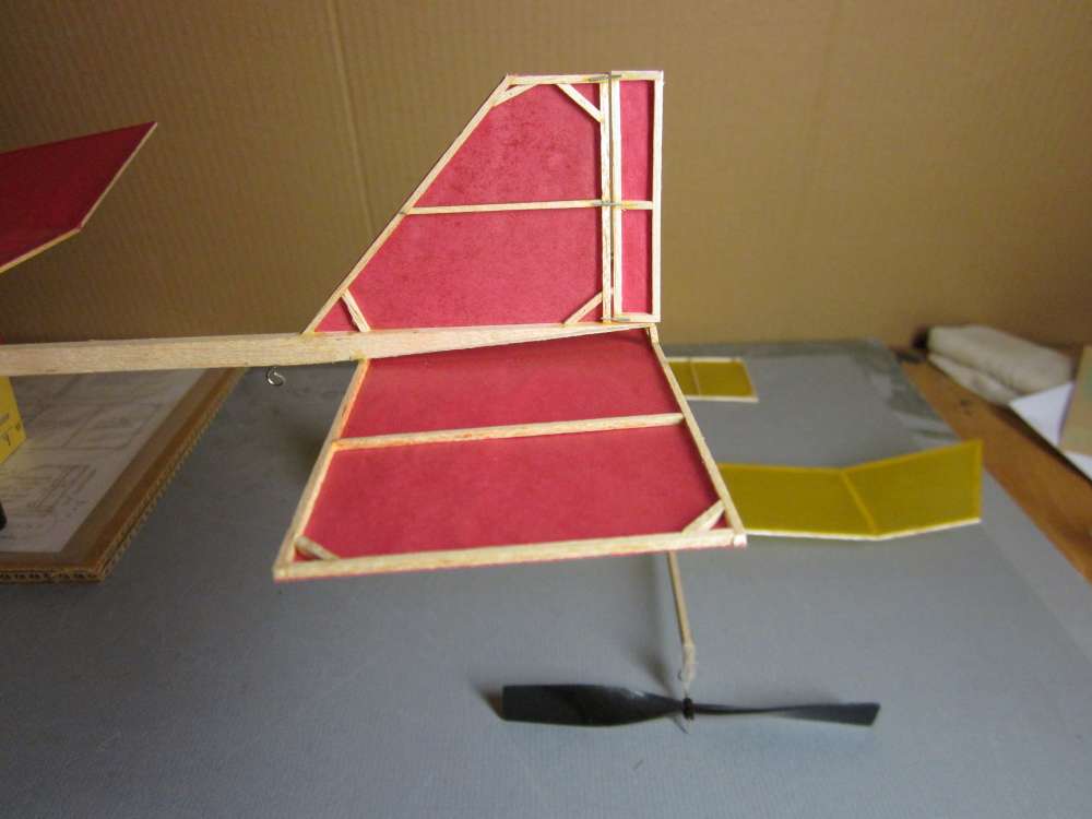
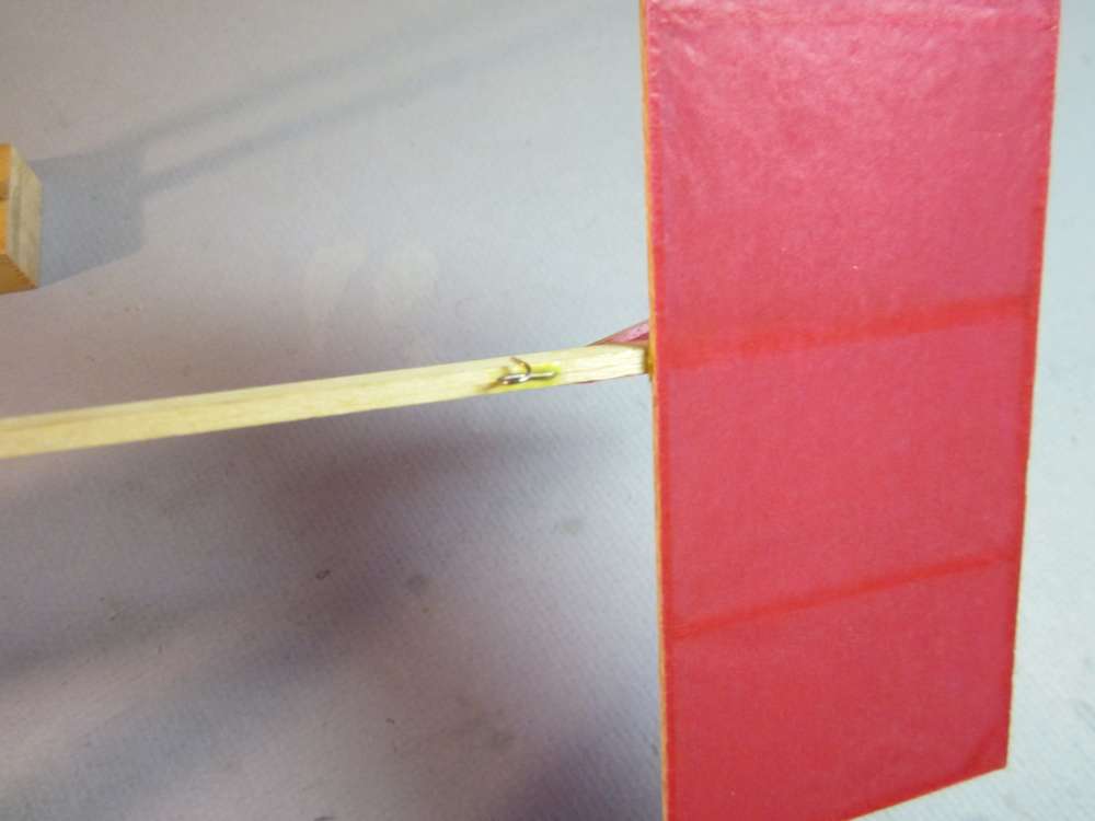
You can see the tailplane shim here, as well as the rudder with stiff iron wire hinges. The wire is from vegetable ties from the grocery store.
This is the final configuration of the tail group. I recommend you build yours like this. The stick tapers from 1/4″ deep at the leading edge of the tailplane to 1/8″ deep at the trailing edge. I used 3/32″ wide sticks for the leading and trailing edges of the tailplane because I had tailplanes warping. I also crumpled the tissue paper before attaching it to the framework. Next I will tell you about another way to deal with that problem.
Later I encountered another problem; warping of the tailplanes. Tissue paper expands and contracts as it absorbs moisture from the air. In low humidity, the shrinking paper stresses the thin balsa structure and causes these warps. A common remedy is to crumple the paper before attaching it to the structure. The slight wrinkles absorb some of the shrinkage. I developed another method of dimpling the tissue by pressing it against a piece of window screen with a damp towel.
I recovered the tailplanes with paper treated in this way and they have remained straight. This method of dimpling the paper is described HERE.
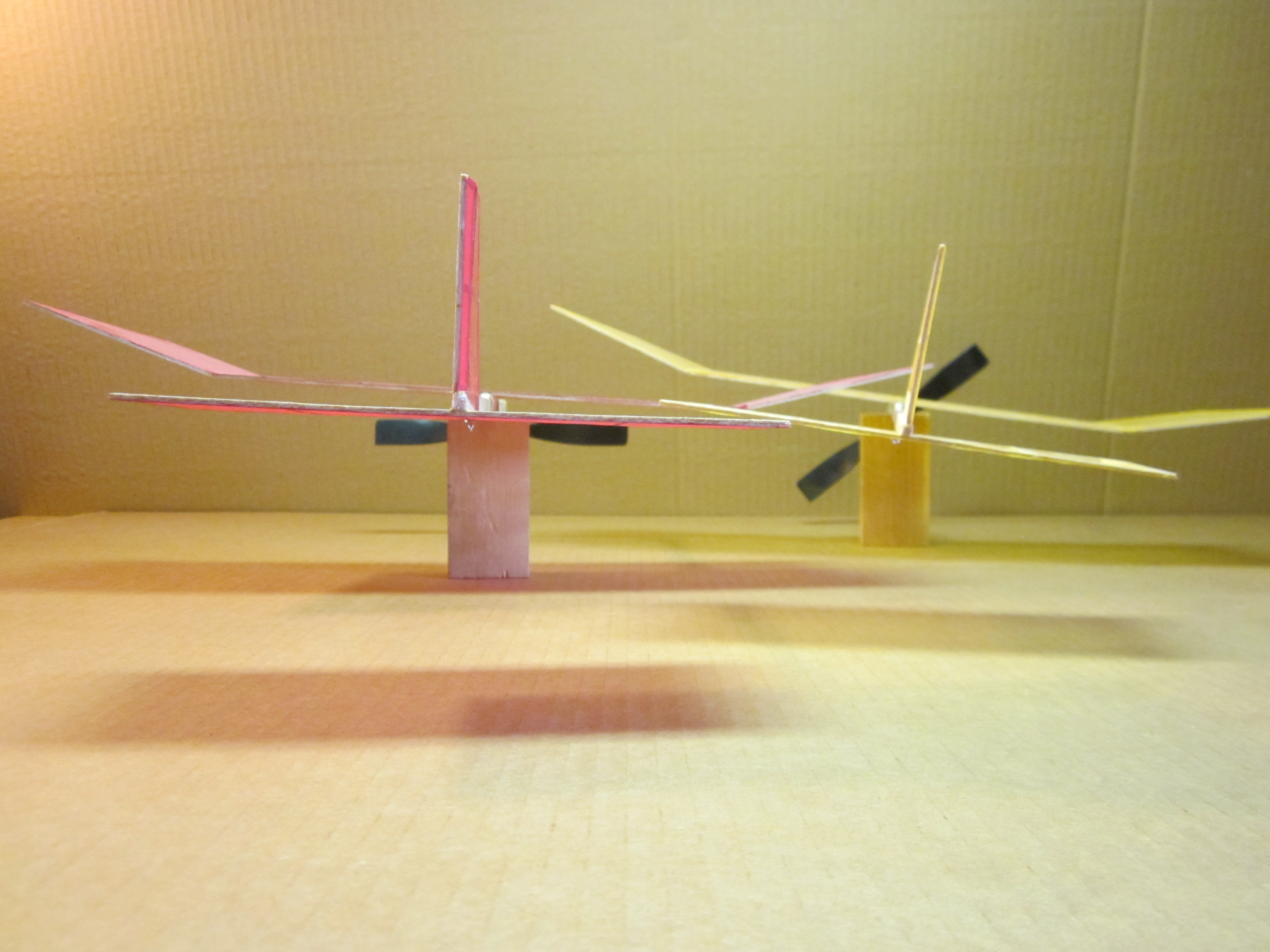
I deflected the rudders 1/16″ left, 9.59 degrees. With up to 500 turns on the 15″ loop of 1/8″ rubber, weighing 2.5 grams, both planes climbed nicely and came down in left circles. The original climbed with wings much closer to level than the one with no washin or washout. That one climbed with the wing steeply banked to the left. A steep bank implies a strong sideslip, which is a downward movement, to be avoided. The original weighed 9.6 grams without motor, wing was at 4 3/8″ from nose, plane with motor balanced 0.55″ behind wing leading edge, 18.3% of the wing chord. The second plane weighed 7.7 grams, wing at 4″, balanced 0.30″ behind wing leading edge, 10.0% of wing chord.
I have not had the opportunity to crank the motor up to full power, I will need a larger flying field for that. It could happen that more torque will cause excessive left banking. If that happens, it can be mitigated by bending a little right thrust into the prop hanger.
Flight Videos
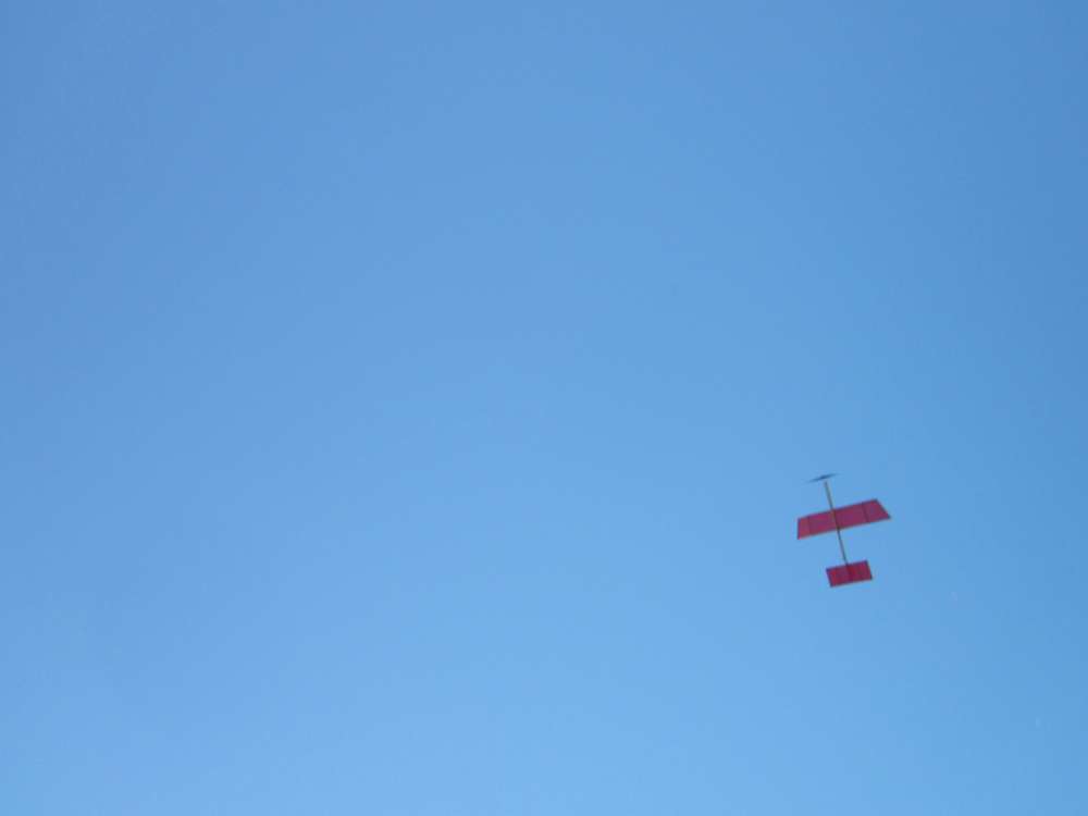
Here it is flying with 1,800 turns on a 21 1/2″ loop of 3/32″ rubber, weighing 2.7 grams. The wing is 4 3/8″ back from the nose, putting the balance point 0.55 inches behind the wing leading edge. This is a short trim test flight of only 37 seconds, but we get good closeup views of it flying and you can see it is flying well, with good trim. It is ready for more power.
Here it has 2,200 out of an estimated maximum 2,500 turns on this motor. I put in a bit of right thrust to open the initial circle and level the wings, but this produced a steep climb and a near stall at launch. Giving it a bit of left bank at launch would reduce the chances of a stall. This gave a flight of one minute, twenty five seconds. The motor was almost completely unwound when it landed, showing that this motor is close to optimum. Wonder how many more turns I can squeeze into this motor and how much time that will give.
Some Builder Notes
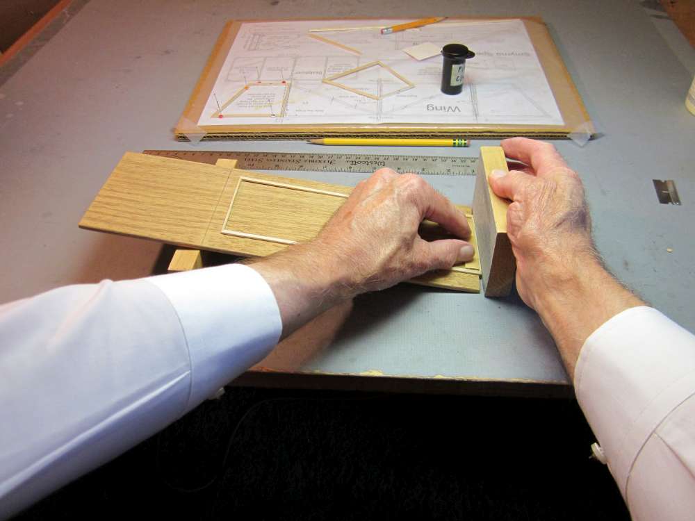
This shows the sanding jig for the dihedral bevel. The dihedral of 1″ on a 3″ span wingtip equals arcsin(1/3) = 19.47 degrees. We must sand half that angle, 9.73 degrees, in each rib of the wing panel and each tip panel. I am going to use a 1 1/2″ block to raise the flat board up to 9.73 degrees. The block must be placed at 1.5″ / sin(9.73) = 8 7/8″ from the end of the board. The panel to be sanded is placed on the board, overlapping the end a little. A wide piece of scrap 1/16″ balsa sheet is used to back up the rib and prevent it from bending during the sanding. The sanding block is held perpendicular to the table and gently moved back and forth to remove wood from the top edge of the rib without removing any from the bottom edge.
The tissue must be kept taught when gluing the hold down stick to the underside of the wing. To do that, a slightly long 1/16″ square stick is sprung into place with a friction fit. After the hold down stick glue has dried, the temporary spreader may be pushed out and removed. The same is done when gluing the tailplane to the stick. This wing has dihedral break lines parallel with the center line; no washin or washout. It is preferable to use washin/washout to counter left roll from motor torque.
The dental elastics must be very tight to hold the wing securely. It is hard to get them over the end of the stick when they are doubled over to make them tight.
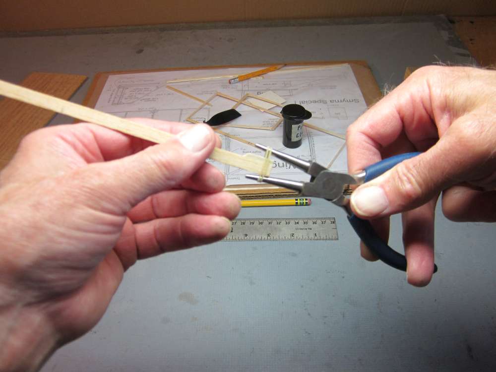
The bands can be easily put over the end of needle nose pliers. The pliers can be opened to stretch the bands. The end of the stick can be slipped between the bands and the bands can be rolled onto the stick.
I found that the wing could wobble when flown outdoors in even slight wind. A wobbly wing makes it difficult to get reliable launches. It will not hold up to the high torque of a fully wound outdoor motor. I devised two ways to prevent the wing from wobbling. We need some kind of saddle to mount the wing to the stick.
I cut four pieces of 1/16″ x 1/8″ medium hard balsa to 5/16″ lengths and glued them to the wing spars next to the center hold down stick. It was very difficult to get them square to the wing, evenly spaced the thickness of the stick that will go between them and with a tight joint. The tiny bits of glue that had oozed out from the joints between the wing spars and the hold down stick had to be filed away to get a tight fit. With the small contact area, these pins might break off easily. A fillet of glue must be applied around the joint to reinforce it. This seemed to work, but it is difficult to assemble.
I cut 1/4″ wide strips cross grain from the end of a 1/32″ x 3″ sheet of balsa and glued them to the sides of the hold down stick. These were pressed in place with two blocks of wood. This was easier and produced a strong joint with the plates aligned square to the wing with a proper gap between them for the stick. Although I used 1/32″ wood, it might be better to use 1/16″ wood with kids who might be rough.
Other Things to Try
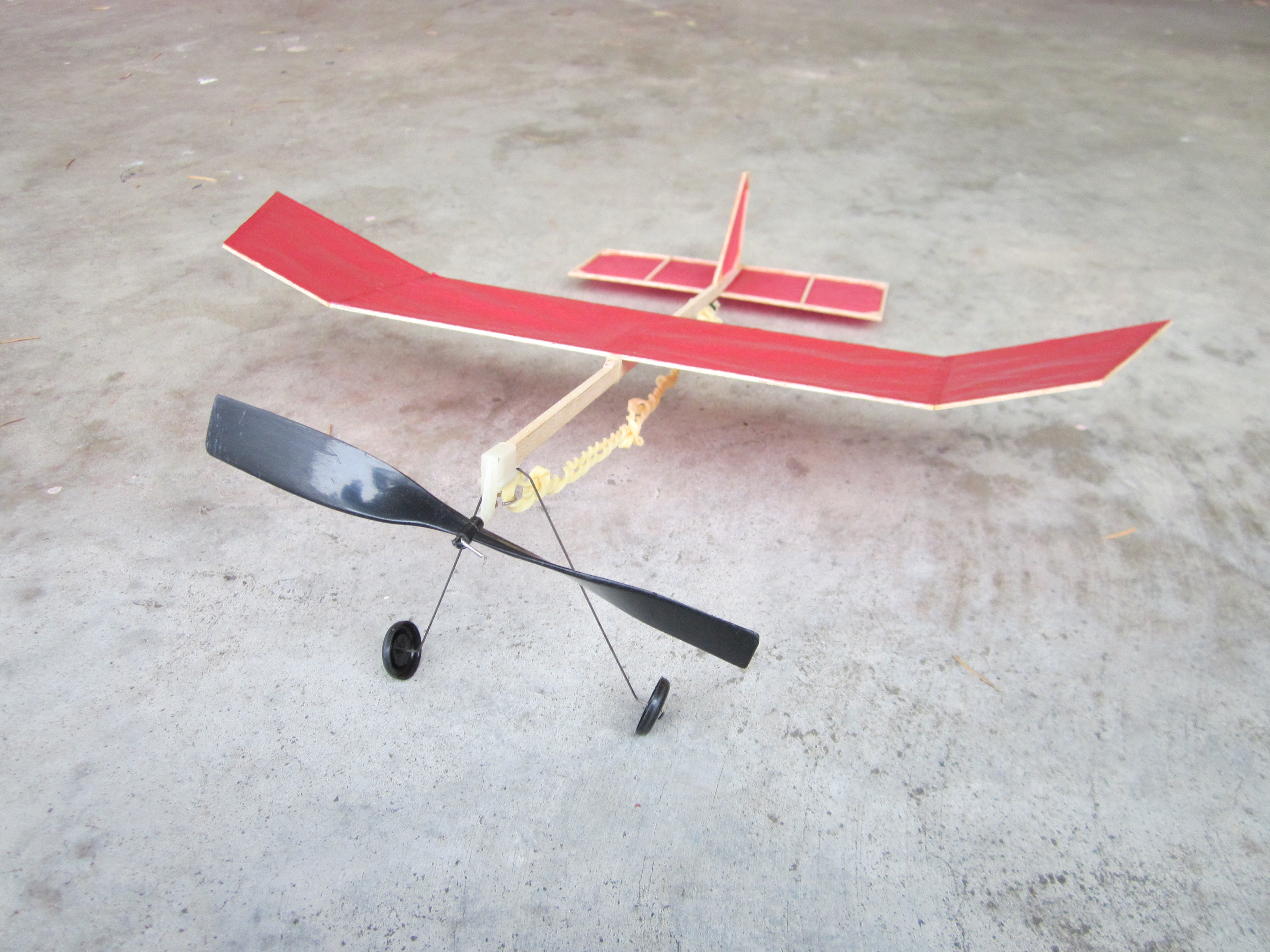
Kids love an airplane that takes off from the ground. It is easy enough to add landing gear. The nose box already has slots for landing gear wire. You can bend up your own wire and make your own wheels or you can buy the necessary 3/4″ plastic wheels and legs. It will be necessary to move the wing forward a bit to get the center of gravity back to the same position on the wing.
A Smyrna Special could be made from an AMA Cub kit. The unmodified AMA Cub stick is too short at 12″. The stick would be stripped into 1/4″ and 1/8″ wide pieces. A 1/2″ long piece of the 1/8″ would be used as a nose block. The rest would be used to make a tail boom. An incidence block would be required for the tailplane. There will be less space for the motor.
The foam plates I have would not be big enough to make the center panel of this wing, unless the dihedral break lines were moved inboard or an awkward splice was used. The wing could be crease cambered for better aerodynamics. Larger plates might be big enough, or Depron sheet could be used. A Smyrna Special made from foam plates could be entered in the Foam Plate event in the Worldwide Postal Contest.
You didn’t read or didn’t understand the purpose of the whole thing. The idea is for a true beginner to complete their FIRST BUILD and get an airplane that is rugged enough for beginner handling AND WILL FLY….. Your “changes” are just complications that will slow down or END the effort. If the builder can have some success maybe they will take up the hobby. If they don’t they are probably gone forever. We started with 5th graders but the idea applies to any age. We don’t want high performance. We want people to to start with enough success that they will become model builders and fliers. This is another bad example of taking a simple concept for beginners and making it another competition for advanced modelers. That kind of thinking probably costs the hobby many potential enthusiasts.
Wow just read this is great. I will try the mods soon.