THE CLOUD TRAMP
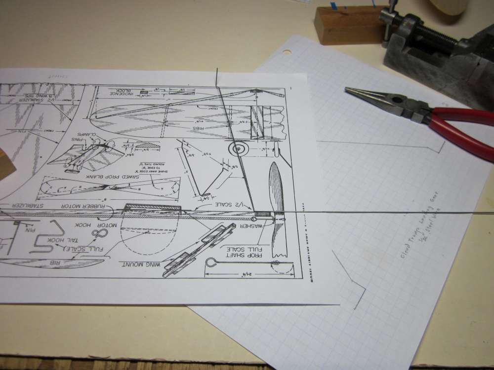
The Cloud Tramp was a late manifestation of Charlie Grant’s basic stick rubber model for beginners and appeared in Model Airplane News, August, 1954. These models were intended to illustrate basic scientific principles of design, trimming and stability as an aide to greater success among aeromodelers. The Cloud Tramp can be built very quickly and flies well. It is capable of five minute flights. There are many videos of Cloud Tramps flying on YouTube. A copy of the plan (half-size, with some full size parts) can be downloaded. You will need to print a plan to correct size for the full size parts.
Save it to hard disk and open it with a suitable application so that it can be printed at the correct A4 (11″ x 8.5″ USA) size. Size it so the wing, stabilizer and fin chords are 3″. The text of the accompanying article can be read on Garry Hunter’s excellent website.
Every year we have a Memorial International Mass Launch of Cloud Tramps (MIMLOCT) to recognize and honor Charlie Grant’s numerous contributions to aeromodeling. Look for the announcement on this site.
PLAN DISCREPANCIES
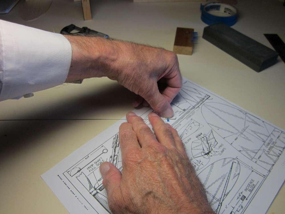
The first thing experienced modelers do is carefully study the plan and read the instructions. You might be surprised at how often you find mistakes on plans. You might be surprised at how often mistakes don’t matter, but you don’t want to build one that does.
The full size and the half size plan show the fin to be 4″ in span. The instructions say to cut the fin 3 3/4″ high. The Volare kit makes it 3 3/4″ while the Vintage Models kit makes it 4″. I make mine 4″. I doubt that it affects performance noticeably.
The plan states the distance from the inboard rib to the center line is 2 3/4″, but it scales 1 3/4″. The full size wingtip pattern is 5″ and the half size drawing scales 5″ from the outboard rib to the tip. The wing semispan is dimensioned and scales as 11″. If we use the 2 3/4″dimension, the lengths add up to 12″, not 11″. Both the Volare and Vintage Model kits put the rib at 2 3/4″ from the center line, which I think is better. They both make the tip to outboard rib 4″ instead of 5″. Planes made from these kits fly just fine. My construction doesn’t use ribs, so it doesn’t matter.
The dimensions of the dihedral block indicate a dihedral angle of arctan((9/64)/(3/8)) = 20.56 degrees where the dihedral diagram indicates a dihedral angle of arcsin(3/11) = 15.82 degrees. It is hard to know how the transition from a flat chord at the center line to a cambered airfoil at the first rib would affect the dihedral. I join my wings differently at the center line and I find that the 3 in 11 works quite well.
The propeller shown in the drawing is impossible to construct, as discussed below in the section on the PROPELLER and here.
CLOUD TRAMP KITS
I am going to show you how to build a Cloud Tramp from stock materials. Over the years there have been several Cloud Tramp kits. You might be able to find one on the secondary market. Currently (2022) there are two kits available. One is being produced by Vintage Model Company in Great Britain, convenient to the European market. I have this kit and can vouch for it.
George Bredehoft has brought back his Cloud Tramp kit, but only as a Short Kit. You will get all the laser-cut sheet balsa pieces and plans/instructions in this very basic short kit ($11). You can add a plastic prop (+$1) or a Superior Props Cloud Tramp balsa prop blank (+$8) as options. All the other items needed to complete the kit are standard hobby shop items and are listed in the instructions. I have several of George’s original full kits and can vouch for their quality.
Both these kits include laser cut sheet parts, which will save you time cutting out the parts. Each kit is a little bit different, and a little different from what I will show you here. You can build them according to the supplied plans and instructions, or you can use the parts, with some modifications, and build according to these instructions. Get it now and fly in the August World-Wide Cloud Tramp Mass Launch!
THESE INSTRUCTIONS
These instructions are an illustrated, step-by-step tutorial on how to build a Cloud Tramp. I suggest you read them through before beginning your build to familiarize yourself with the materials, tools and processes required to make a Cloud Tramp. You will find that there is a lot here, but don’t let that discourage you. Each step is clearly and completely described to make it easy for you to carry it out.
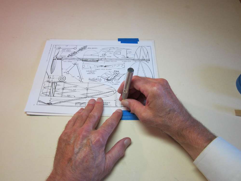
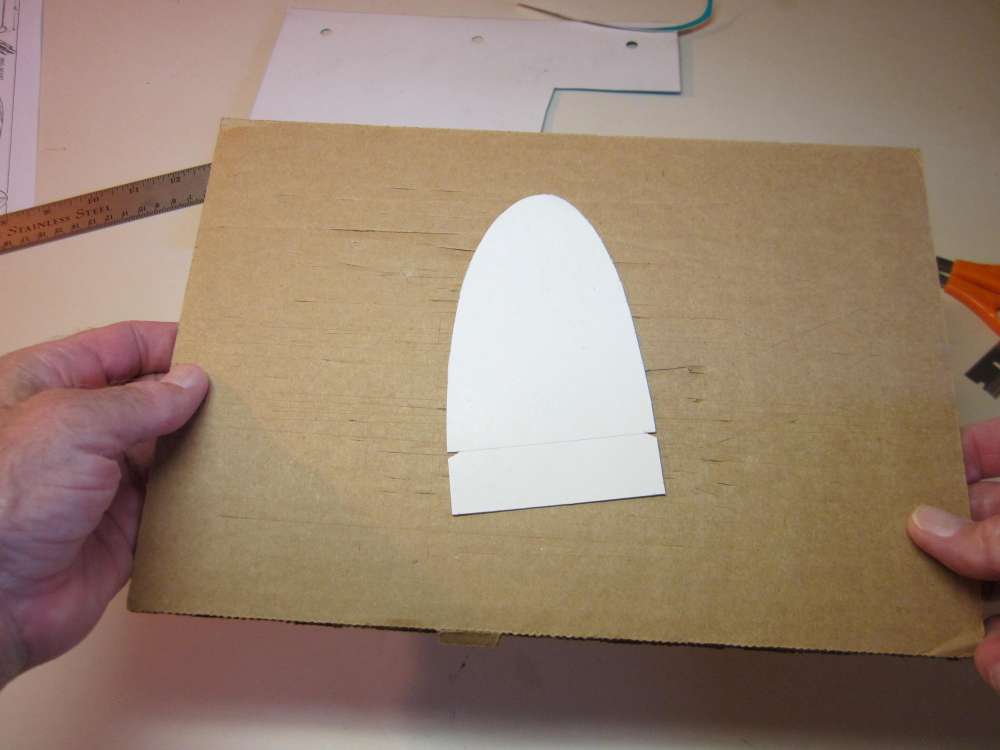
THE TEMPLATES
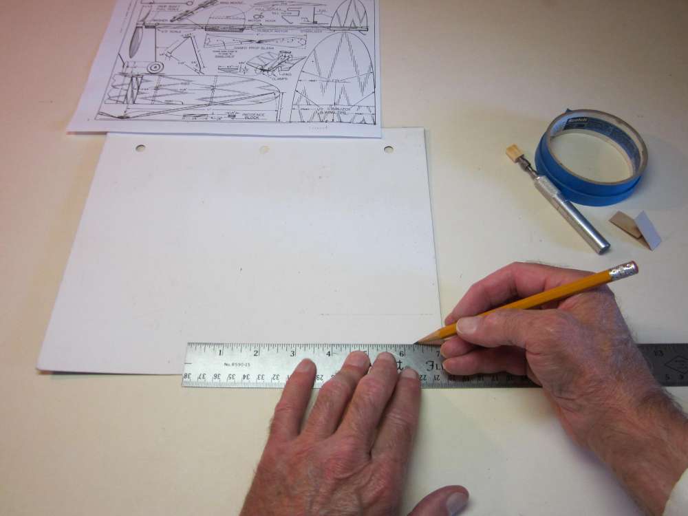
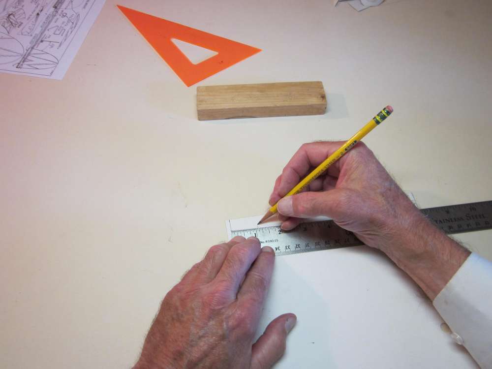
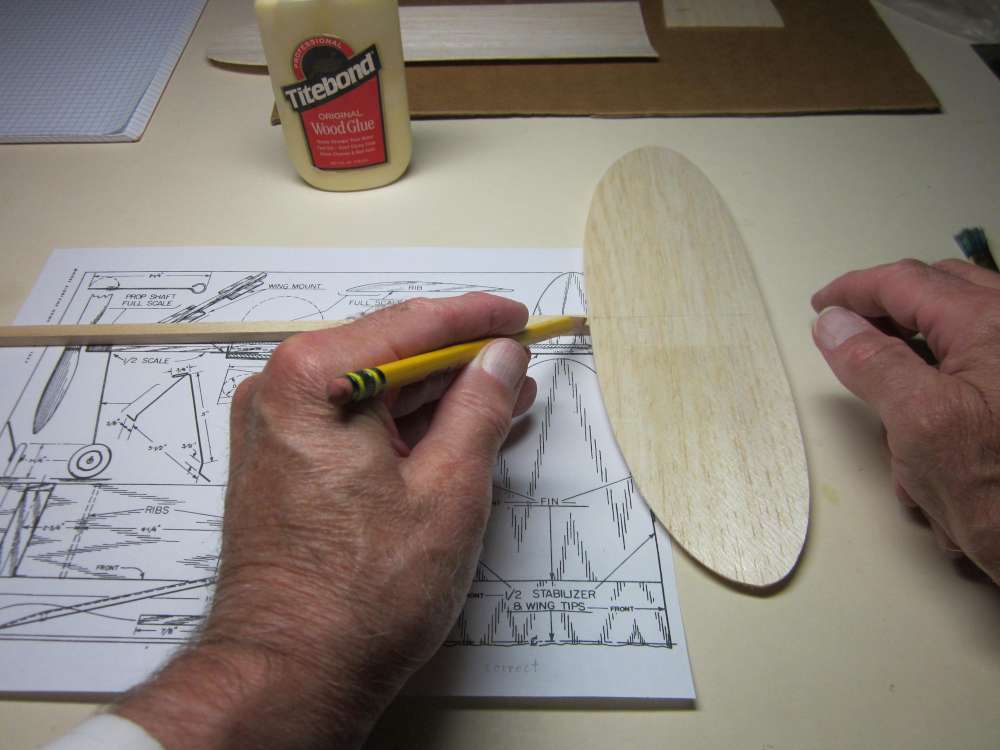
We start by making cardboard templates to guide the cutting out of the sheet balsa parts. Use cardboard such as is found in cereal boxes or notebook pads. The wing/tailplane/fin pattern is 5 1/2″ long and 3″ wide. It is taken right off the plan.
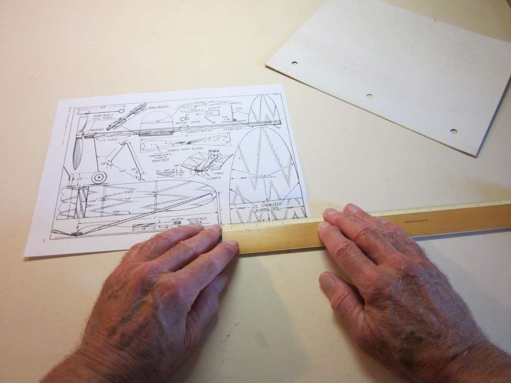
Check that the wing/tailplane/fin chords are exactly 3″. If not, adjust your printer settings accordingly.
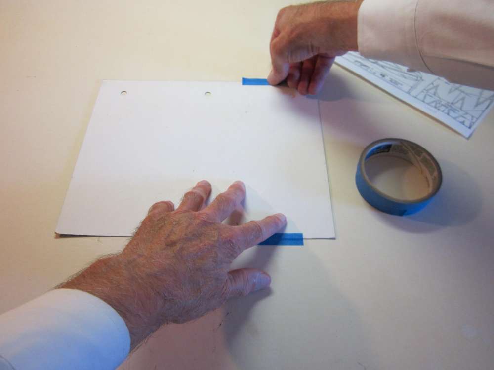
Tack tape your cardboard to your building board.
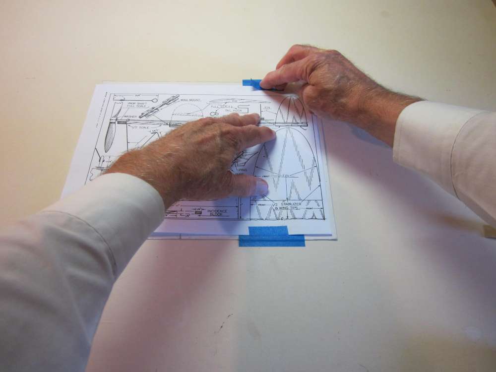
Tack tape the plan over the cardboard. Make sure the plan parts do not extend beyond the cardboard.
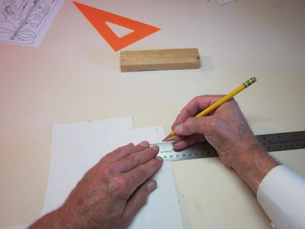
Transfer the plan to the cardboard by poking through it with a pin. I use a pin vise to make it easier. Start by poking holes on the tailplane center line about 1/8″ in from each edge.
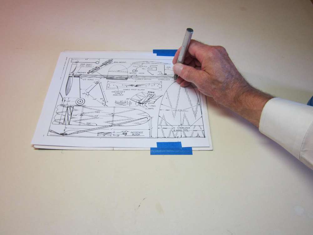
Poke holes all around the perimeter, spaced such that the line segments between them appear to be essentially straight. Pinholes will be closer together where the curve is sharpest. Where the edge is straight, it is necessary to poke holes only at each end of the straight portion.
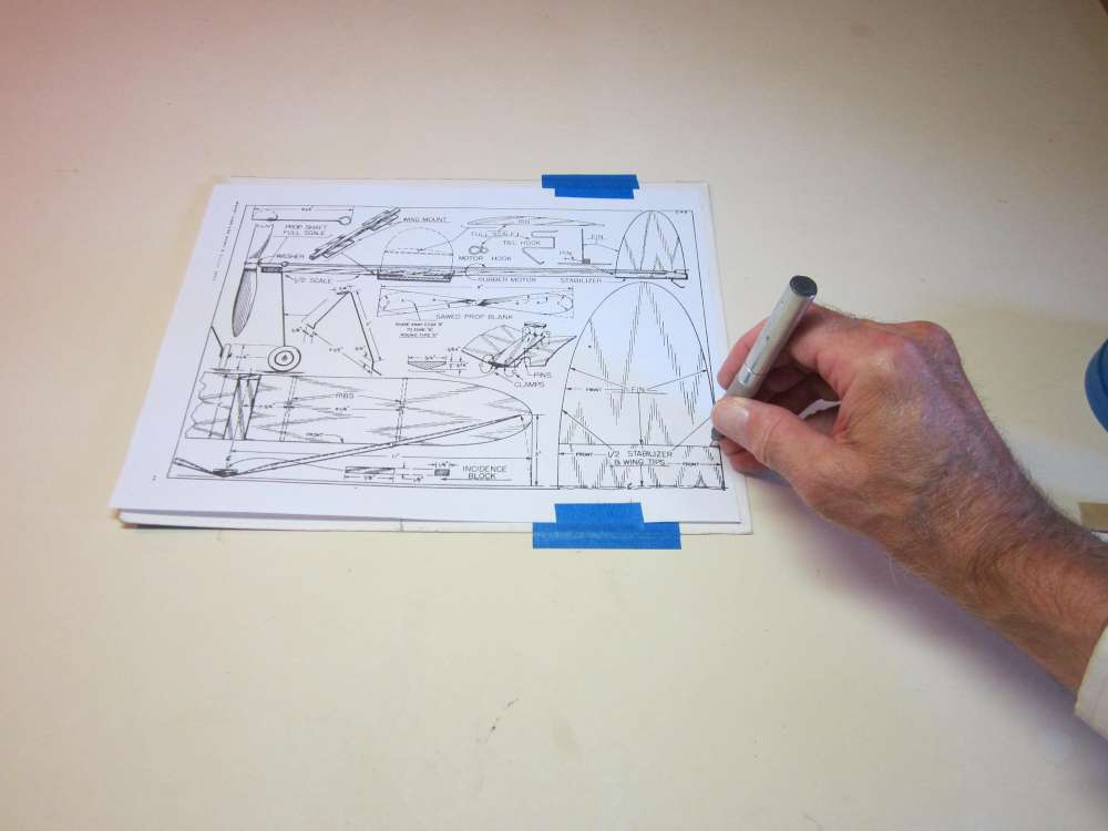
Poke holes about 1/8″ in from each edge on the fin root chord. This pattern will be used to make each wing half, the stabilizer and the fin.
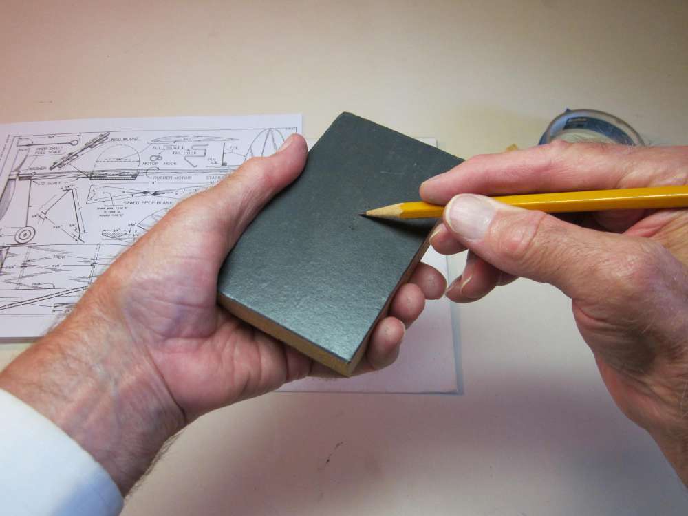
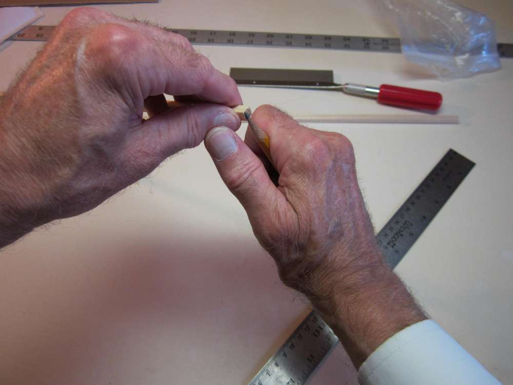
Sharpen your pencil to a chisel sharp point on a block of fine sandpaper. Remove the plan from the cardboard.
Draw the fin root chord and the tailplane center line through the respective pinholes.
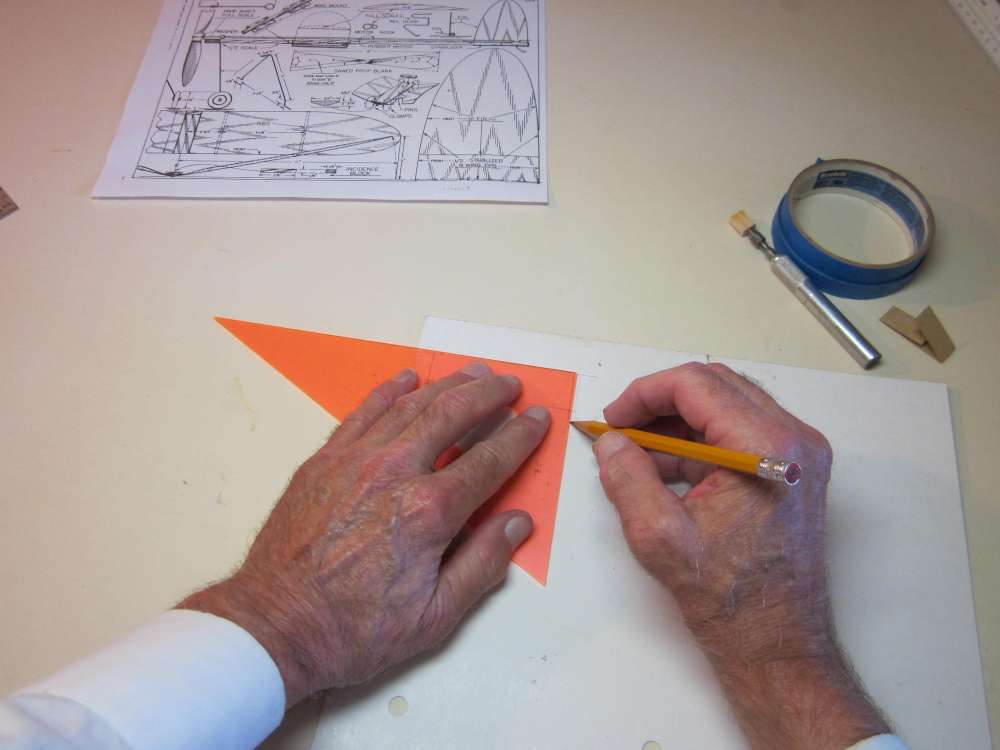
Draw in the straight portions of the leading and trailing edges.
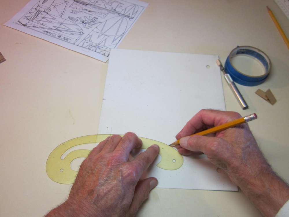
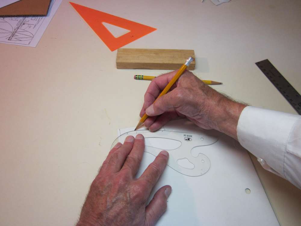
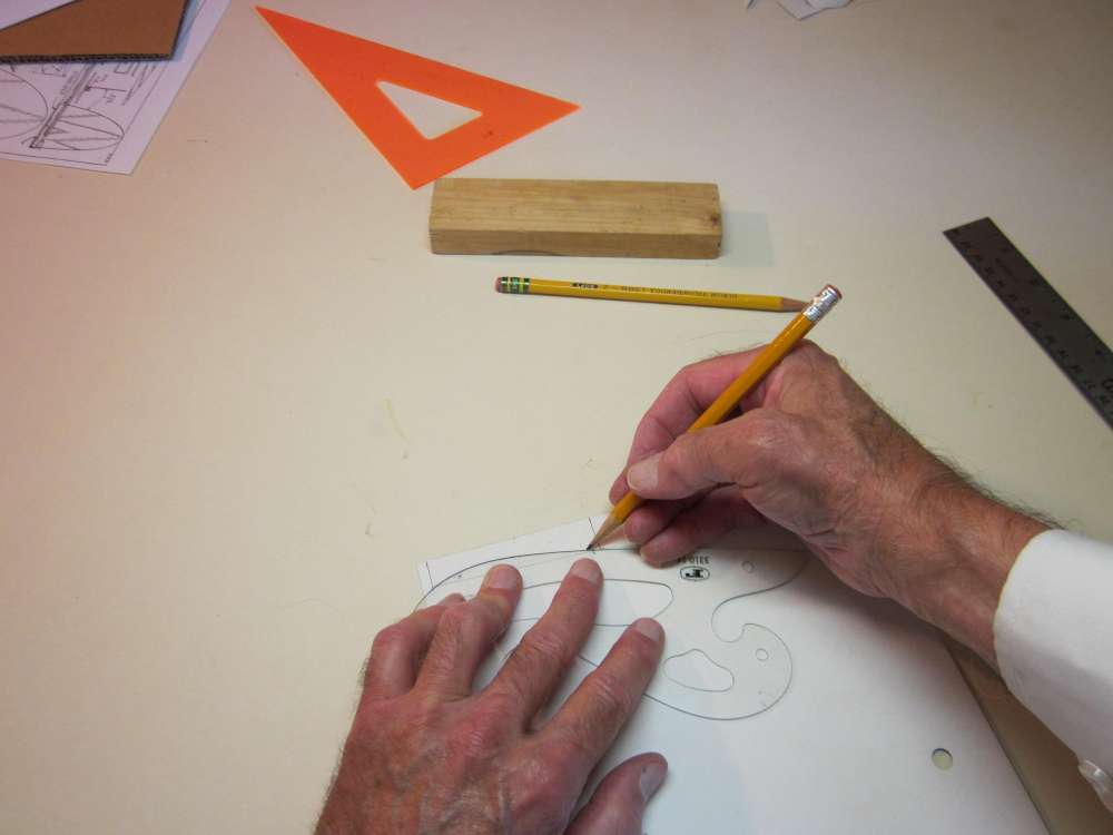
Draw in the curved portions of the outline, matching short arcs of the French curve to the pinholes.
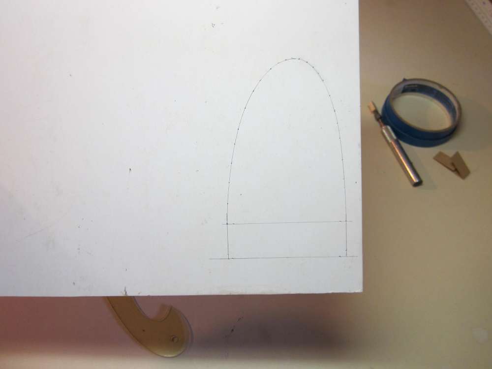
Here is the completed drawing.
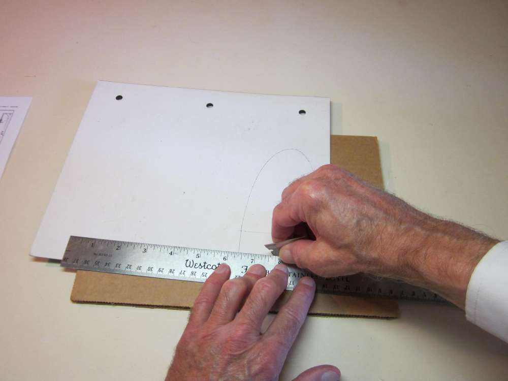
Cut the straight portions of the outline with a straightedge and blade. (Don’t cut across the bottom of the fin.)
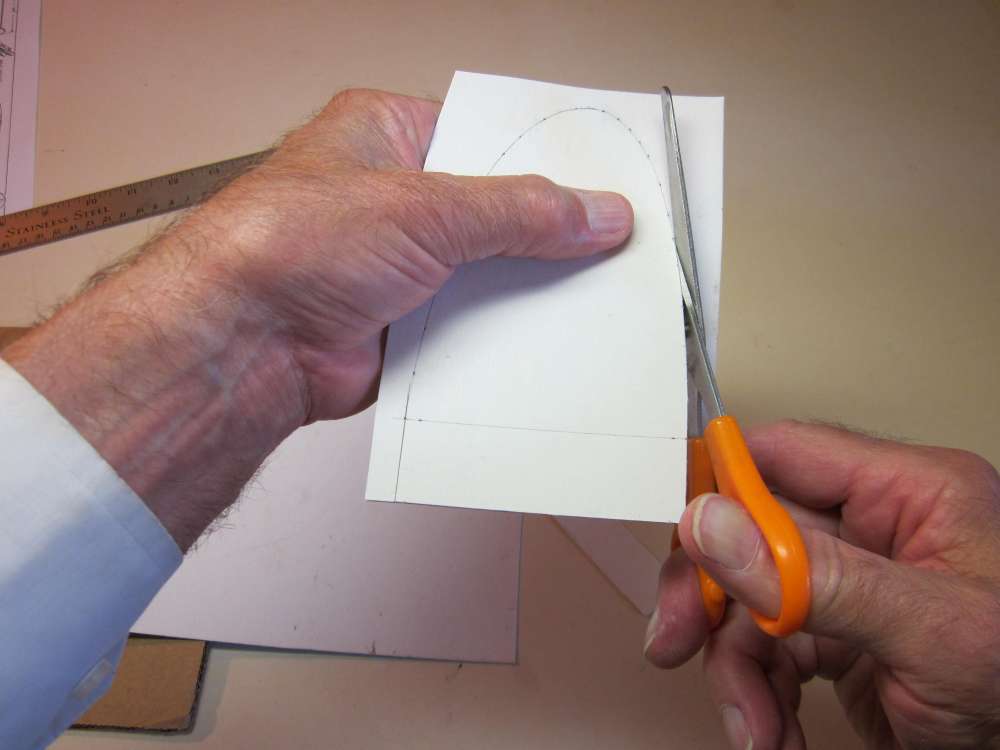
Cut around the curved portions with scissors.
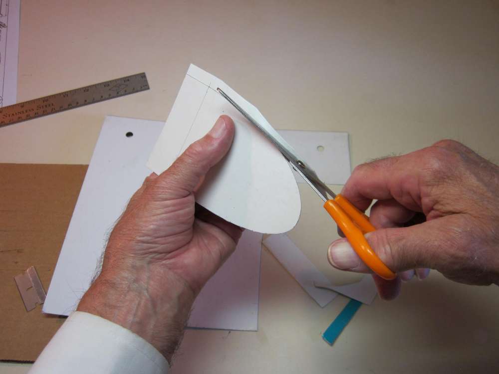
This can be easier if you cut roughly around a little bit out from the final cut curve.

Make short cuts at the ends of the fin root chord.
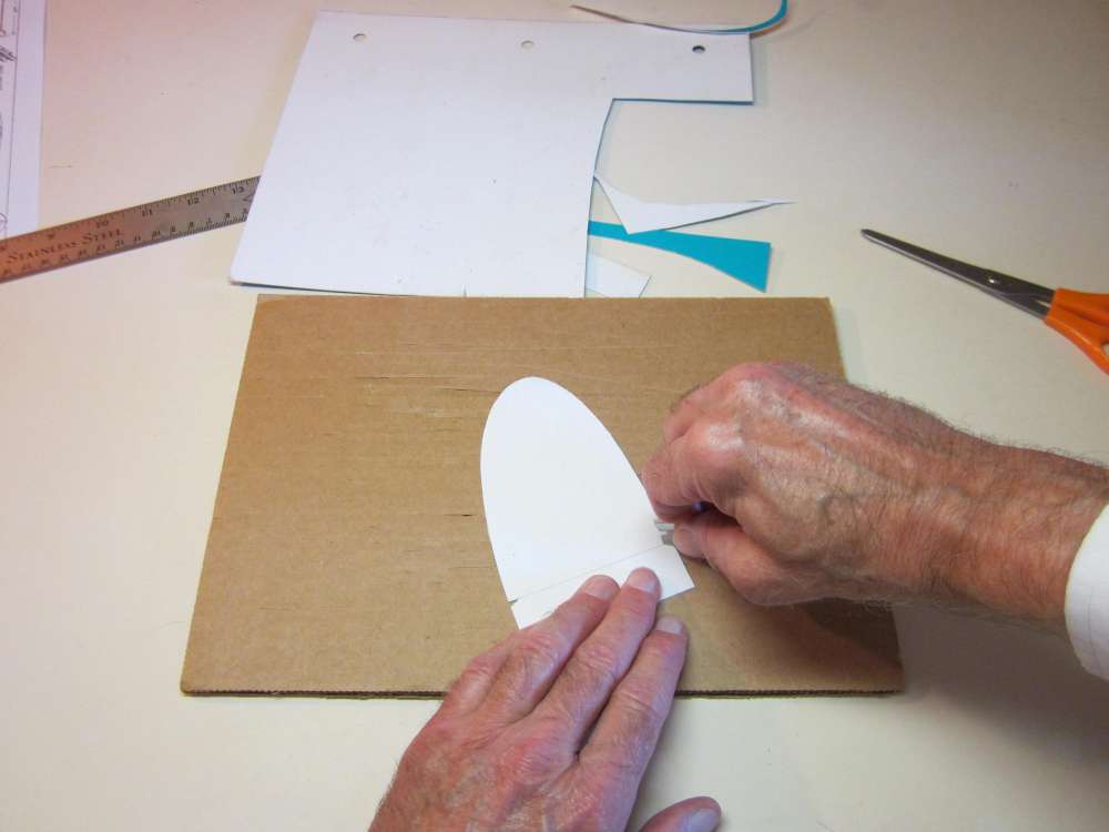
Cut at a slight angle to make triangular notches. These will be used to locate the pattern on the balsa sheet when cutting out the fin.
Here is the completed wing/tailplane/fin template, per the plan.
One improvement that I make is to add a rudder tab to the fin.
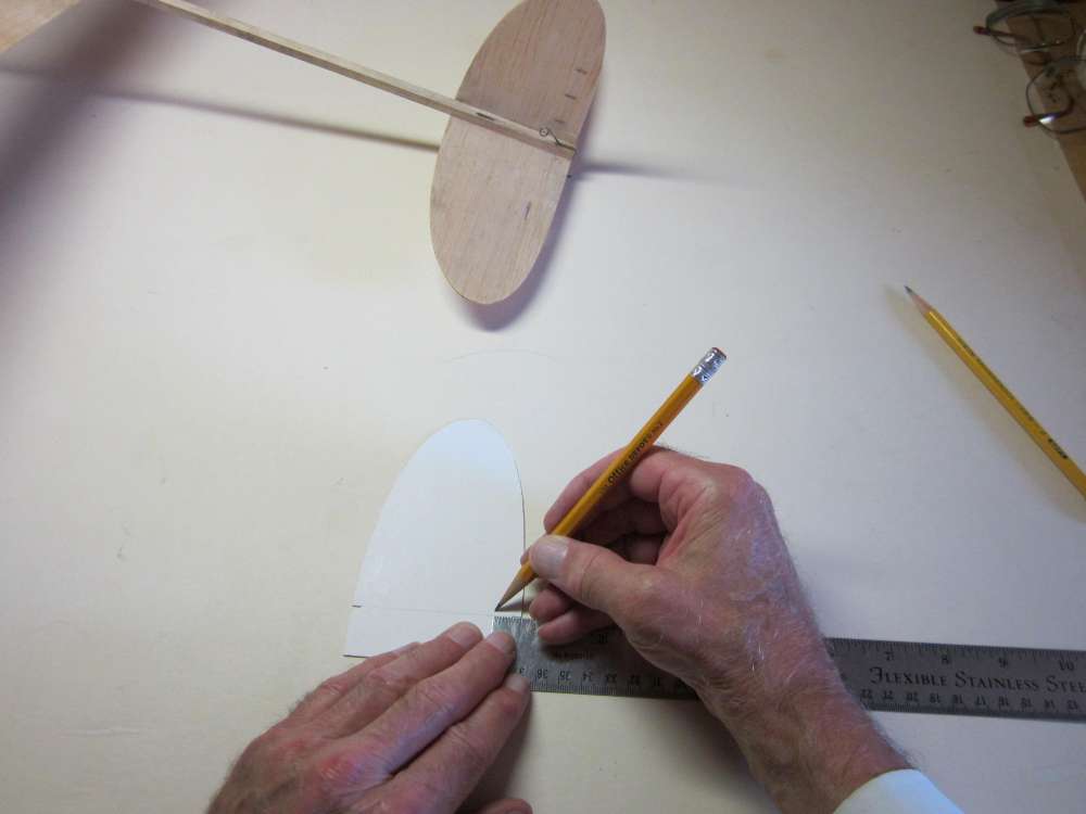
Make a mark 1/2″ in from the trailing edge at the base of the fin.
Draw a line perpendicular to the base about 3 1/2″ long. This will be the hinge line of the rudder.
Put marks on this line 1/2″ and 2 1/2″ above the base of the fin. Remember that the base of the fin is offset from the edge of the pattern.
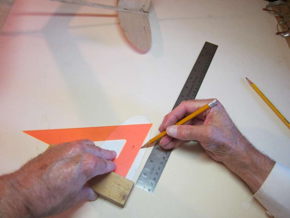
Draw perpendiculars to the hinge line at each of these marks, here the top.
Draw perpendiculars to the hinge line at each of these marks, now the bottom.
Poke pinholes in each corner of the rudder. When we use this pattern to cut a fin from sheet balsa, we will poke a pin through the holes to mark the locations of the corners of the rudder on the balsa.
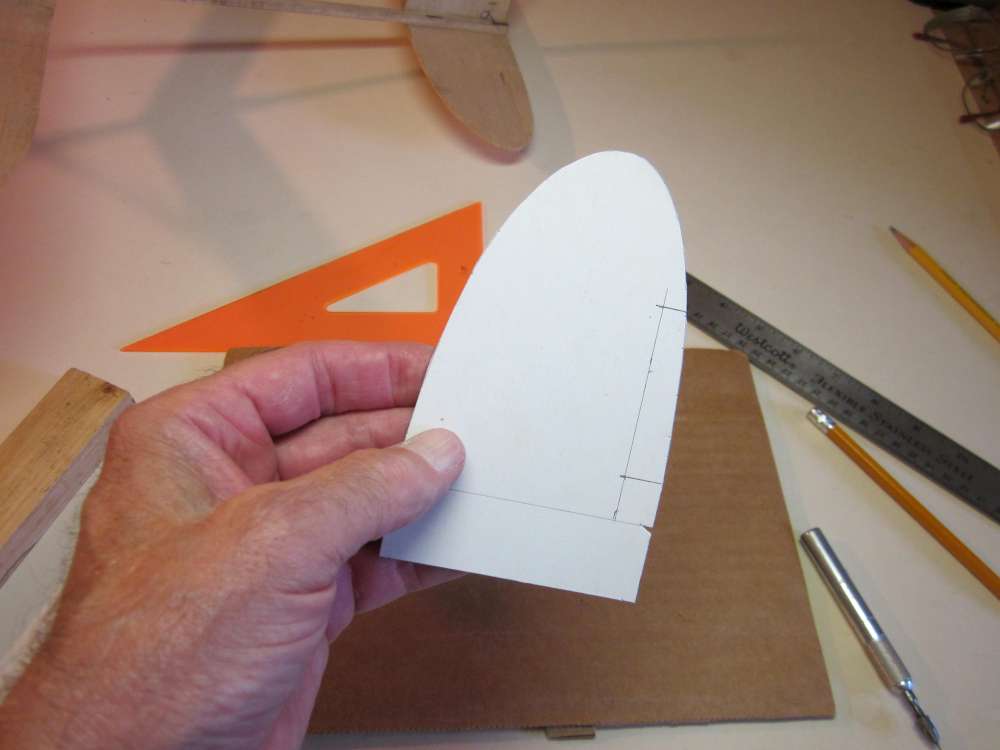
Here is the finished pattern with the rudder added.
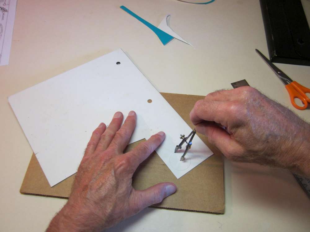
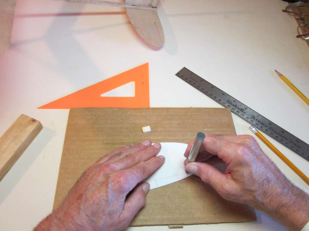
Draw a 1 1/4″ diameter circle, 5/8″ radius. This pattern will be used to rough cut the wheel laminations. Four of them will be glued together and turned to make each wheel.
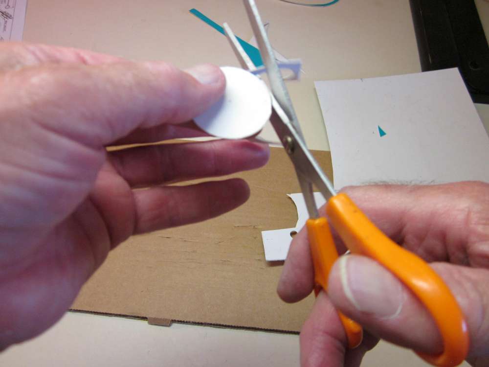
Cut out the wheel pattern.
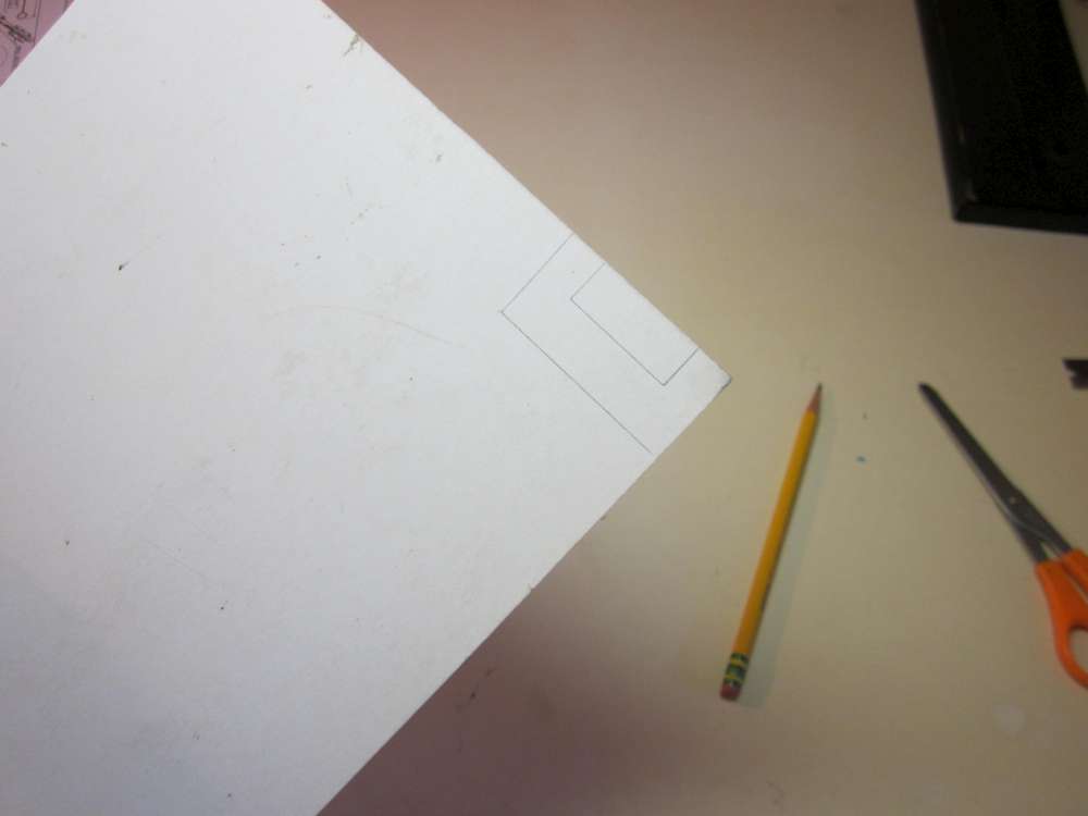
Draw the wheel diameter gauge. This will be used to check the wheel diameter when we turn it down. It is 2″ long and 1″ wide. It has a 1/2″ x 1 1/4″notch centered on one side.
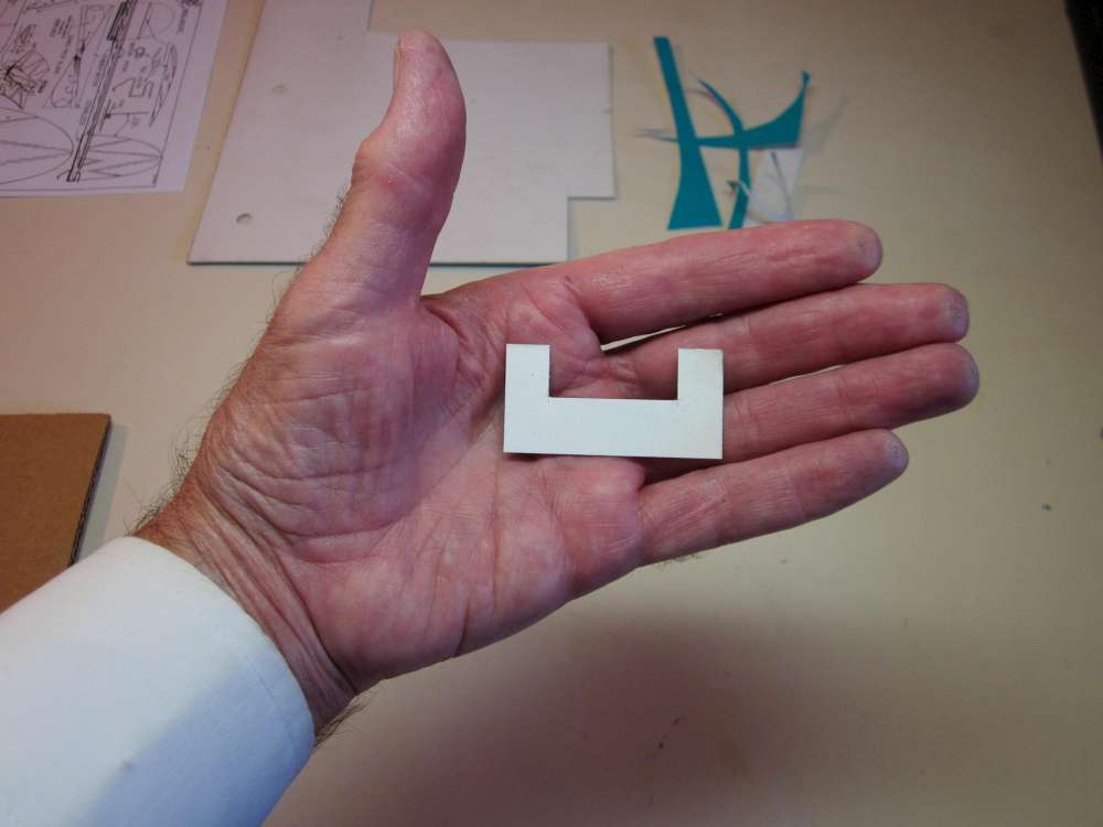
Here is the completed wheel diameter gauge.
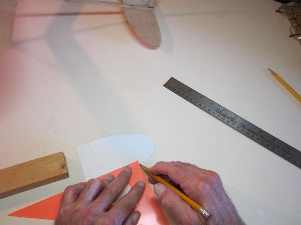
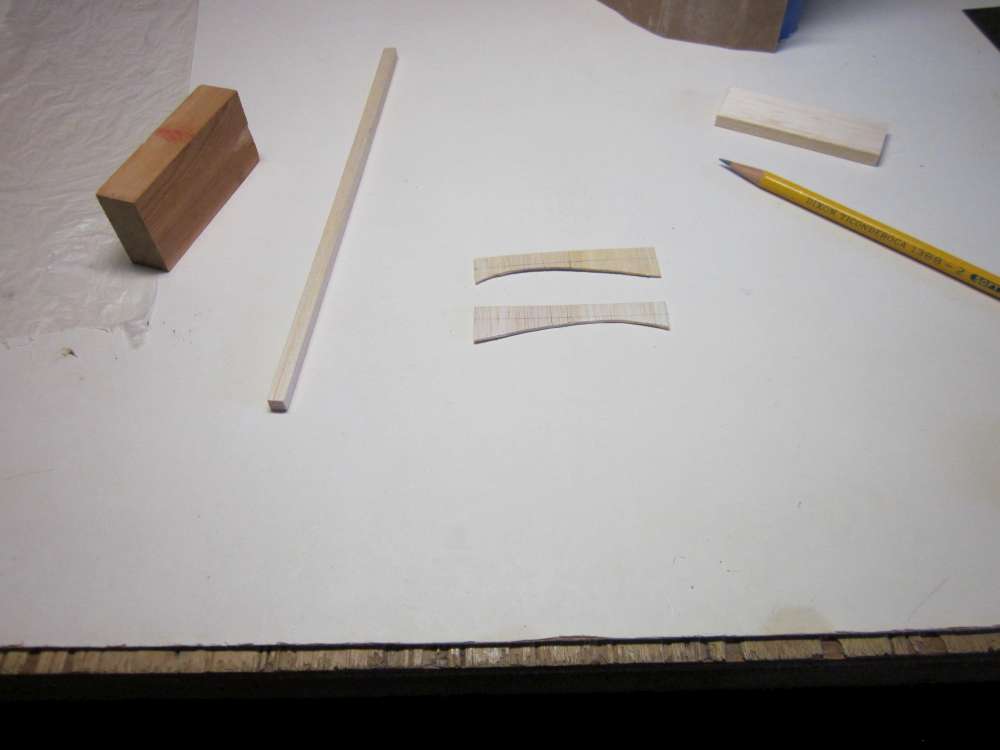
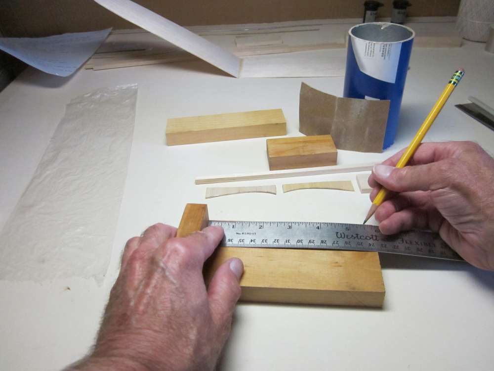
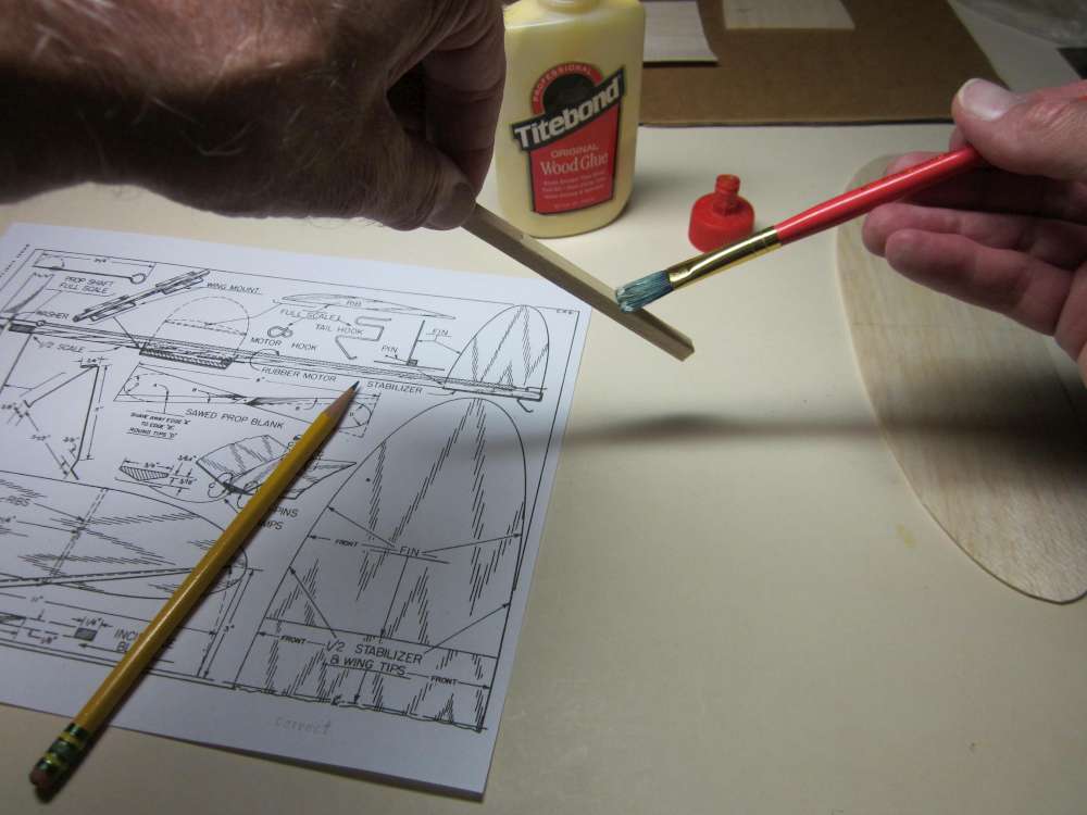
The next template is for a part that is not shown on the plan. I devised a better way to attach the wing to the fuselage that uses two 1/16″ sheet balsa side plates. This is simpler, stronger and aerodynamically better, since it is more compact and maintains a cambered airfoil across the center of the wing.
This template is for those side plates. We start by drawing the shape on a piece of pattern cardboard.
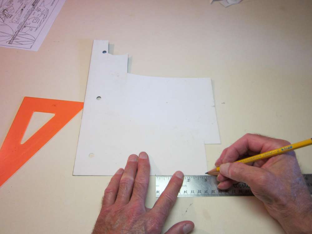
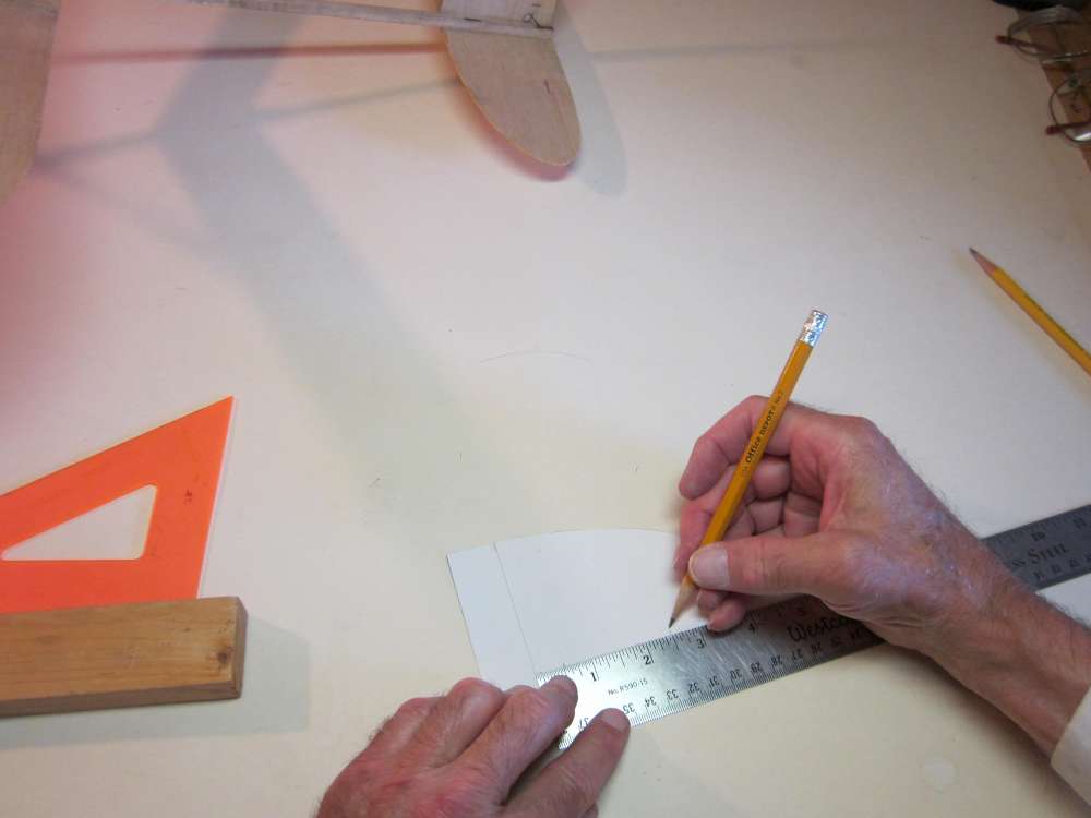
The wing is formed from a 3″ wide sheet of 1/16″ (or 1/20″ if you can get it) balsa. It is curved to make a cambered airfoil. The straight chord line connecting the leading and trailing edges of the arc is shorter than 3″. Also, the airfoil is at an angle to the stick, further slightly foreshortening it’s horizontal projection. The result is that the side plate must be 2 15/16″ long. So we lay out a line 2 15/16″ on the edge of our pattern cardboard sheet.
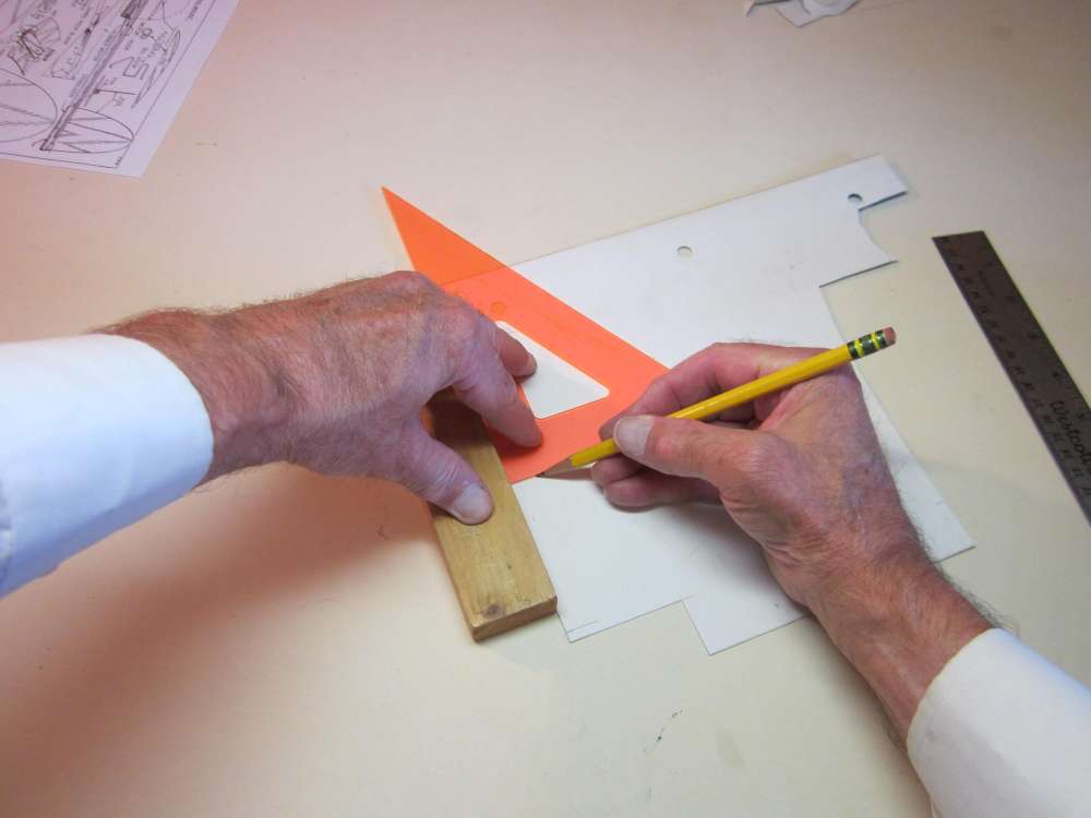
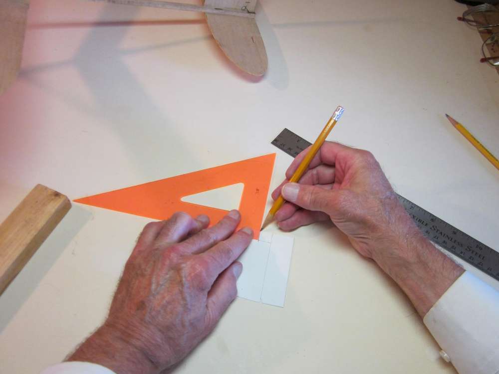
Draw perpendiculars to that baseline at each end.
Put a mark 1/2″ from the edge on one perpendicular and 5/8″ on the other.

Draw a line connecting these two marks. This is our airfoil chord line.
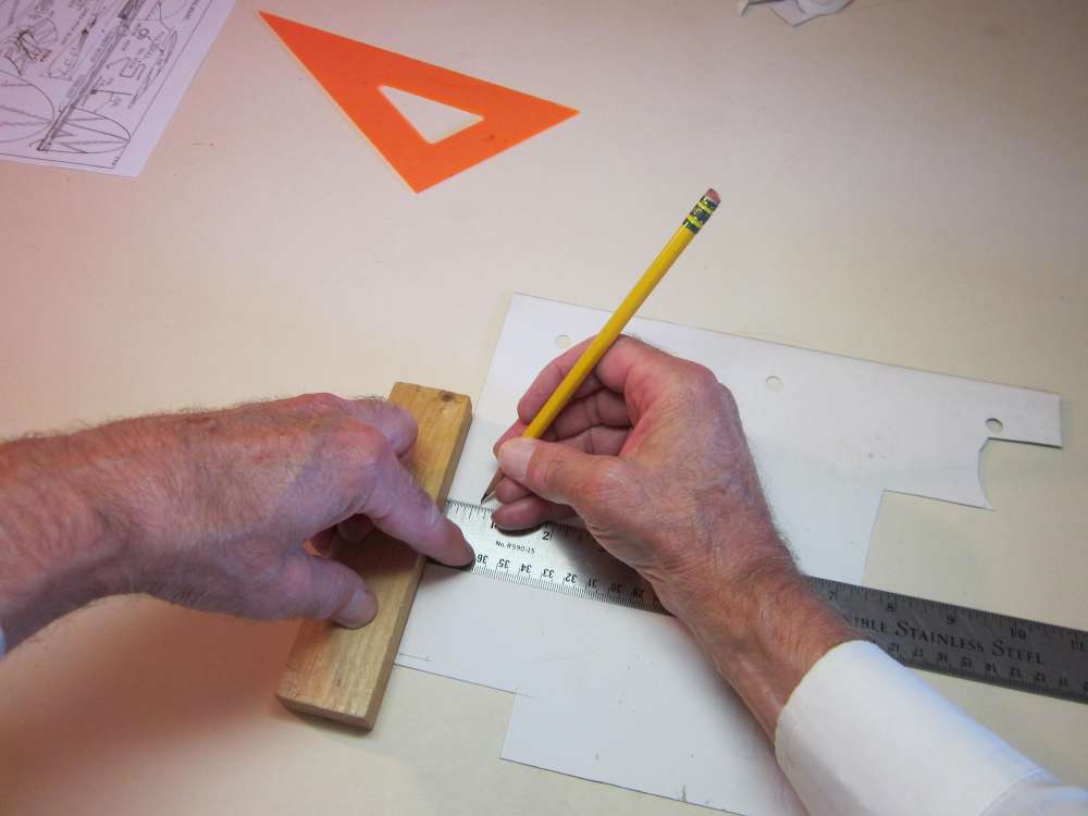
Put a mark on the chord line 1 1/16″ from the shorter perpendicular. This is the location of the point of maximum camber.
Make a mark offset 1/4″ above that location mark. (Inside the trapezoid.) This is the point of maximum camber.
Use a French curve to draw in the forward arc of the airfoil. The tangent to the curve should be parallel with the chord line at the maximum point and it should pass through the leading edge. Slide the curve along until it meets both of these conditions, then draw in the arc.
Use the French curve to draw in the aft arc of the airfoil. The tangent to the curve should be parallel with the chord line at the maximum point and it should pass through the trailing edge. Slide the curve along until it meets both of these conditions, then draw in the arc. The two arcs should join smoothly at the maximum camber point.
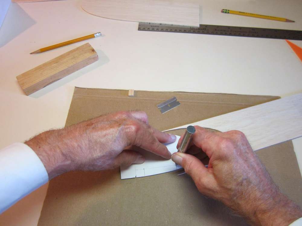
Cut through both perpendiculars. I didn’t get a picture, but next cut along the airfoil arc to cut the pattern from the cardboard. Use the French curve to guide the blade, proceed slowly and carefully to avoid nicking the curve and make several deepening cuts rather than try to cut it all the way in one slice. Precise work must be done slowly and carefully.
Here is the finished pattern.
THE WINGS, TAILPLANE AND FIN
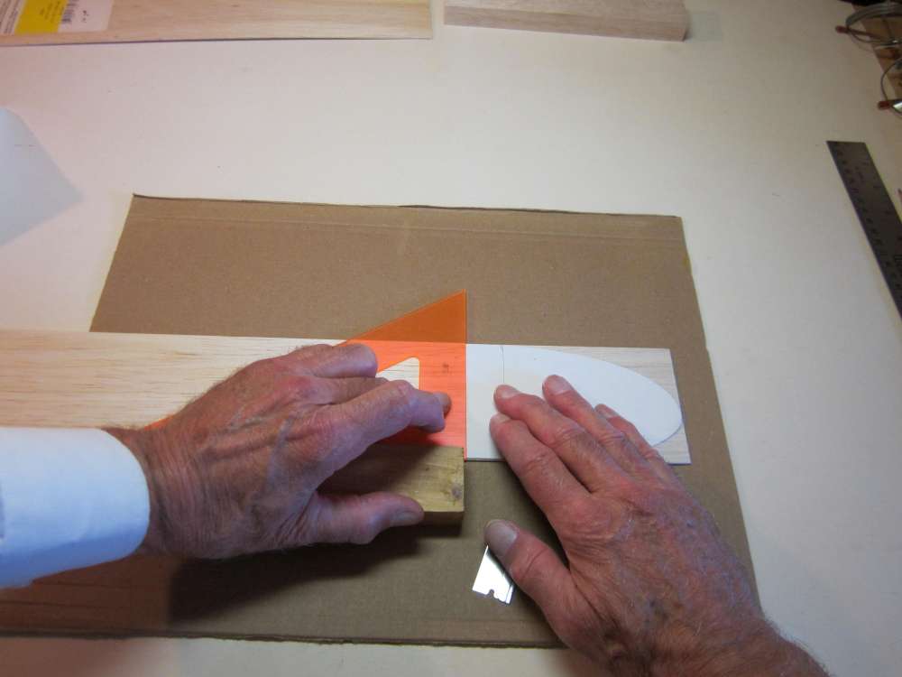
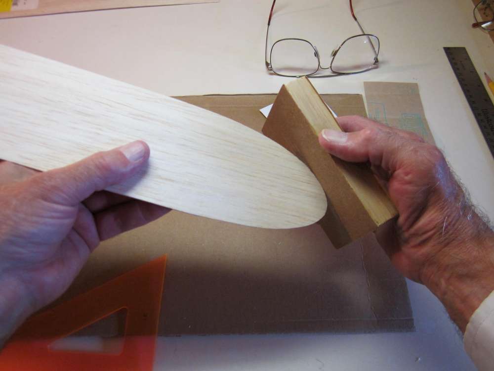
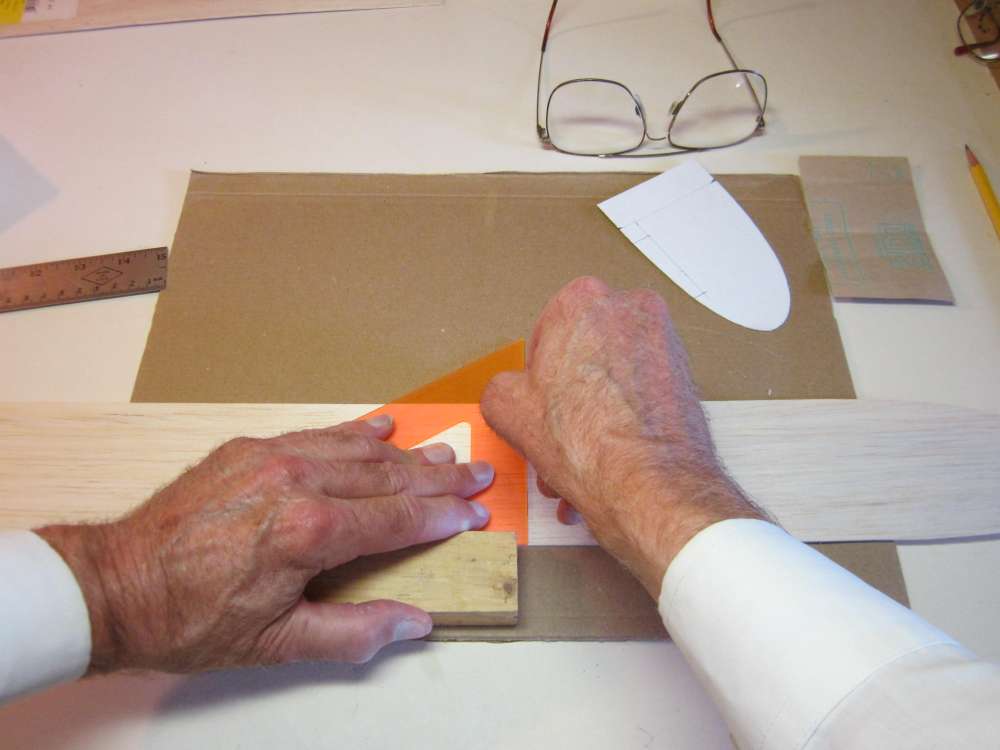
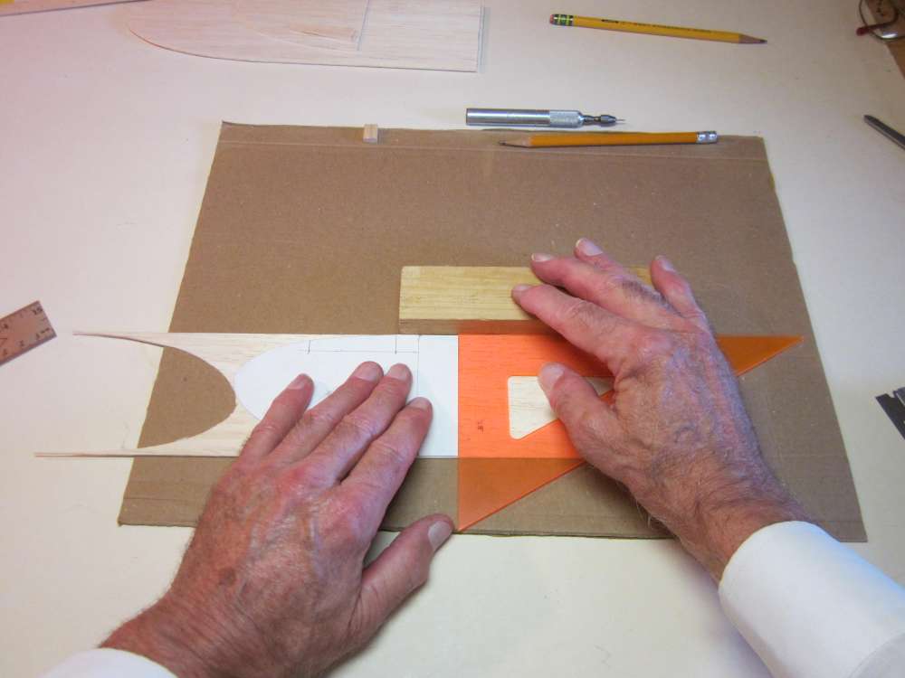
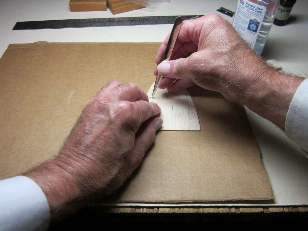
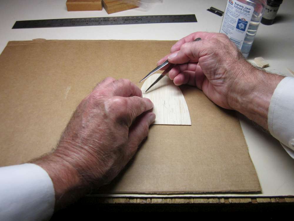
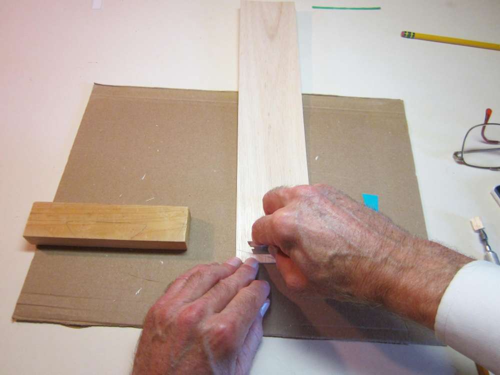
Place a block along the edge of the balsa sheet, align a triangle with the block and set the flat end of the wingtip template against the triangle, with the tip at the end of the balsa sheet.
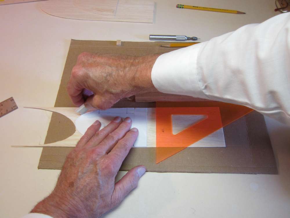
Cut around the wingtip. Draw the blade in the direction that the grain will pull the blade out from the pattern, rather than into it. Make several deepening cuts, rather than try to cut all the way through on one sweep. When cutting across the grain at the tip, go lightly in many sweeps. Cutting across grain can split the wood. You can work the blade up and down, stabbing the point into the wood.
You may lightly sand the edge with fine sandpaper to remove any roughness.
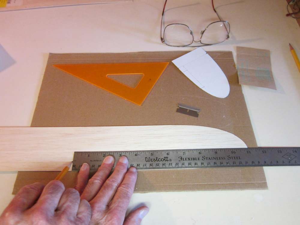
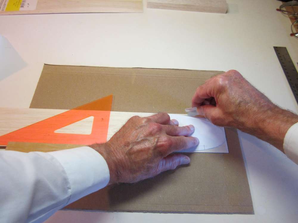
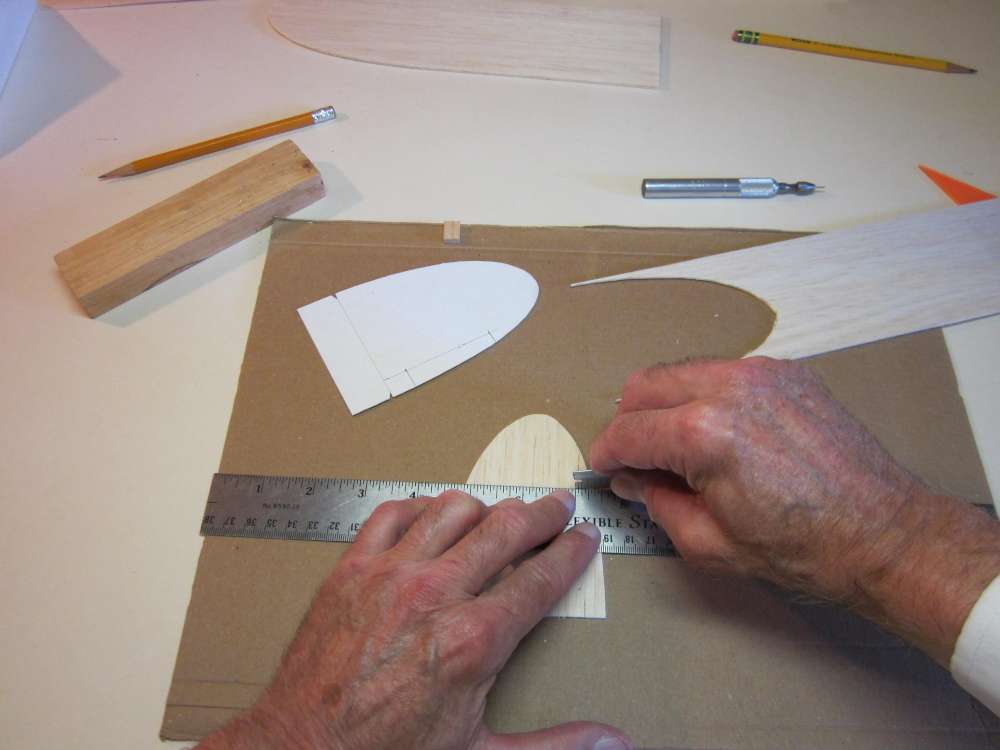
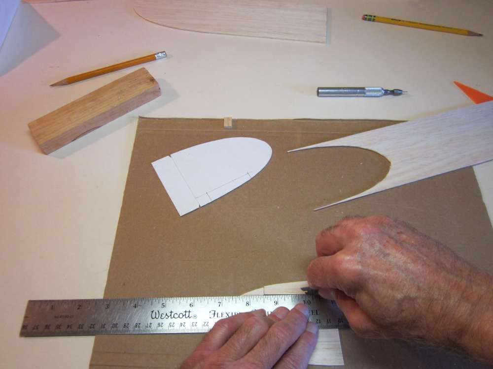
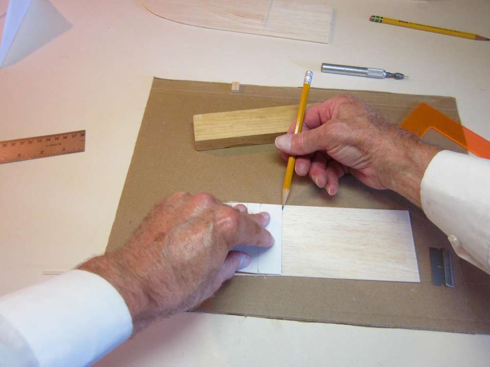
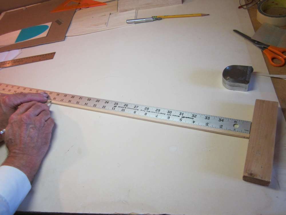
Each wing panel is 11″ semi span. Measure 11″ from the tip and put a mark at the leading edge.
Align the triangle with a block along the leading edge at the mark and cut the wing to length.
I’m not sure why there is no picture of the cutting out of the second wing. The root end of the second wing could be at the same cut and the wingtip template would be placed on the sheet so its tip is 11″ away from this end.
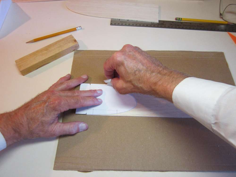
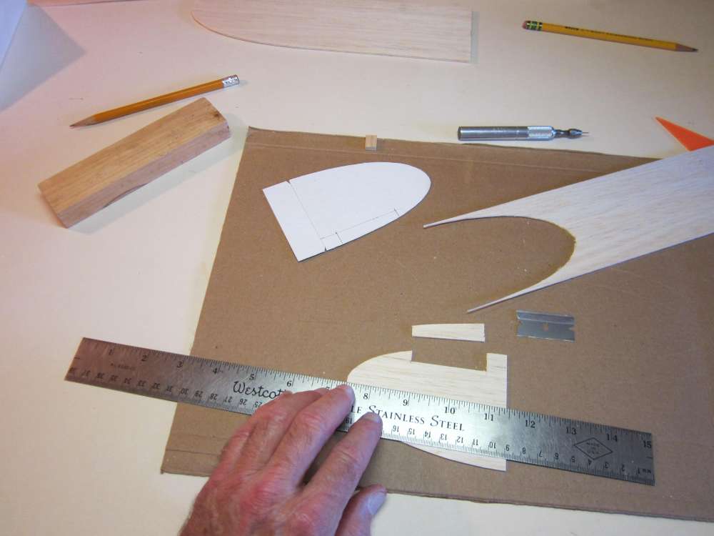
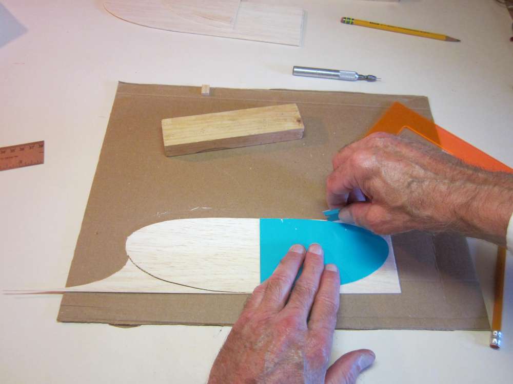
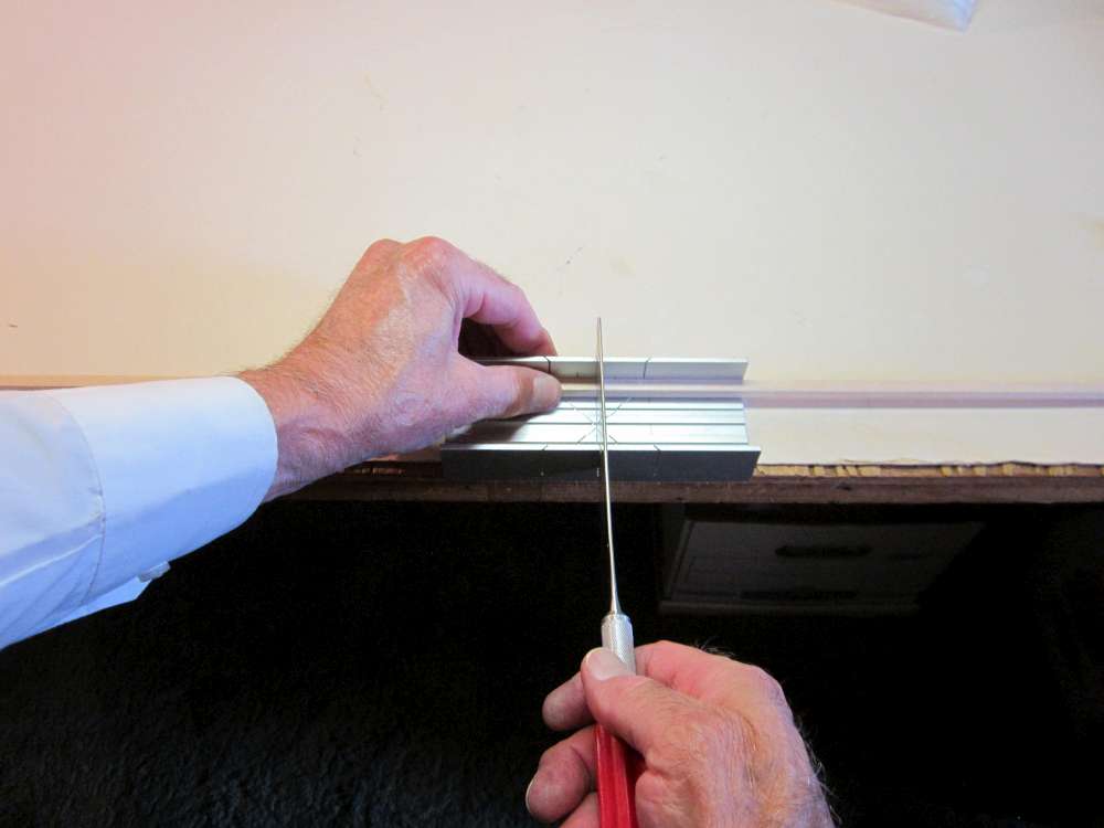
Be sure the end of your sheet is cut square. Align the notches at the bottom of the fin with the end of the sheet and cut out the fin.
Poke pinholes through the corners of the rudder to mark their locations on the balsa fin.
Align the straightedge parallel with the base of the fin and cut the top edge of the rudder. Be careful here, this cut is across grain. Pulling the blade out across the edge can pull pieces off the edge. Press down with a rocking motion to make this cut, or turn it around and cut from the edge inward. In a similar way, cut the bottom edge of the rudder.
Cut along the hinge line between the pinholes to separate the rudder from the fin.
Here is the rudder separated from the fin.
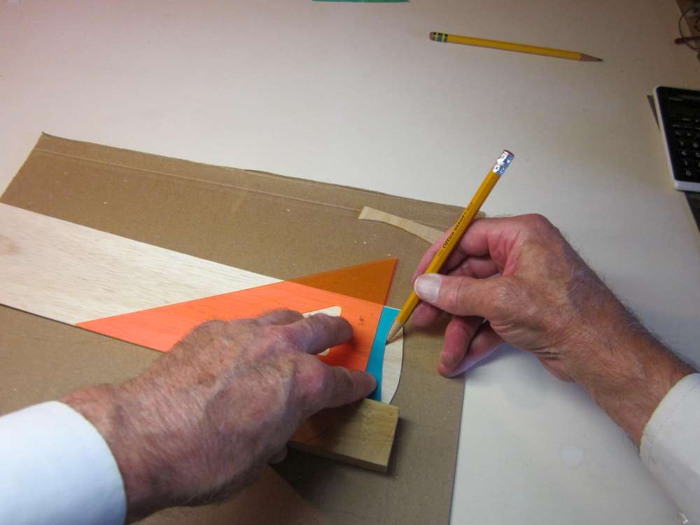
Align the triangle with the edge of the balsa sheet using a block, set the center line of the tailplane against the triangle so it just touches the fin cutout. (Usually this would be the second wingtip.) Note there is a slight overlap.
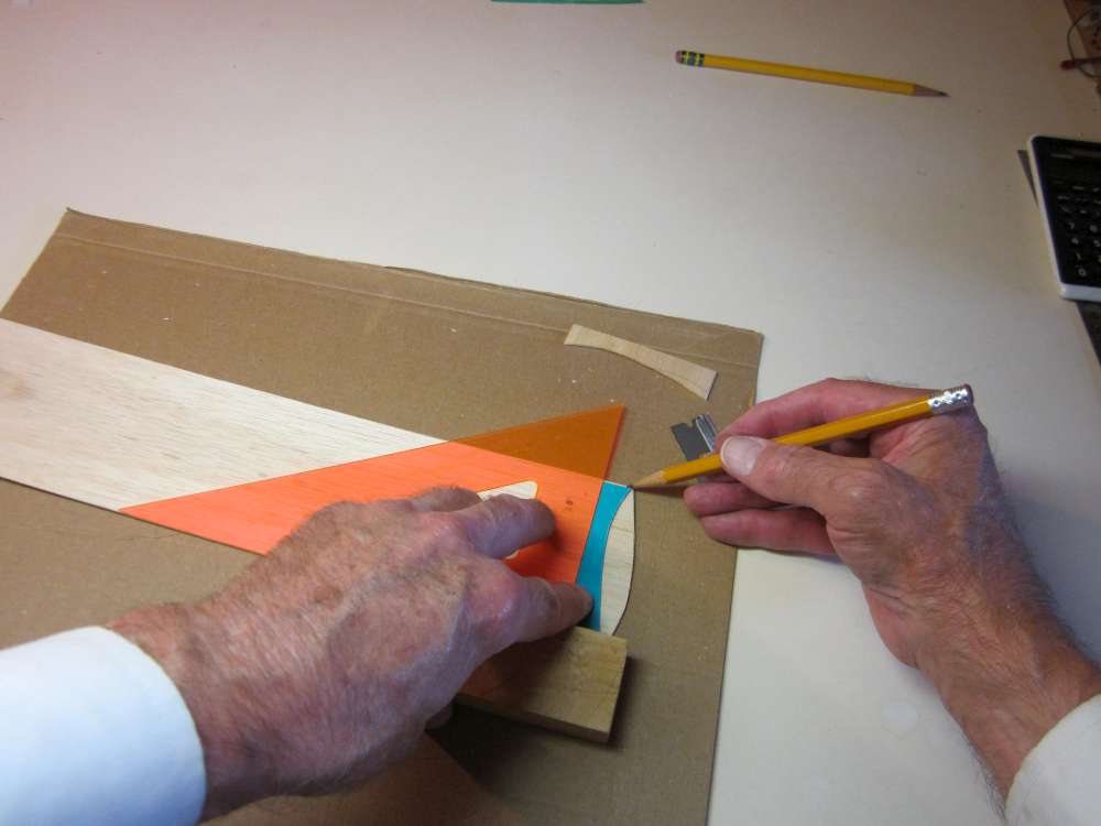
Cut around the perimeter of one half of the tailplane.
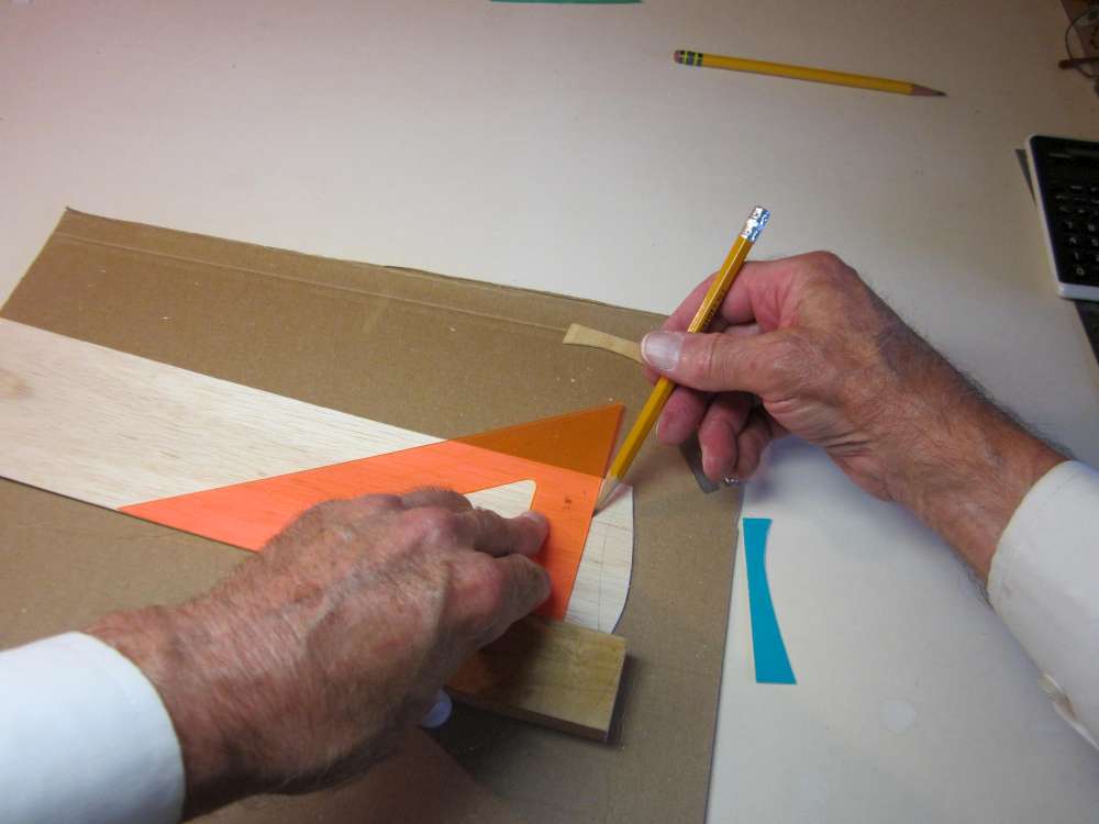
Lightly draw the center line of the tailplane.
Flip the pattern over and align its end with the pencil center line, then cut out the second half of the tailplane.
I have made several Cloud Tramps. I don’t know why I cut the pieces in this sequence. Usually I would cut two wing halves, the tailplane next and the fin last. It doesn’t matter, as long as you can arrange the parts so you can get all of them from the sheet without overlap or running out of material. This can be a problem if you have only one 3″ x 36″ sheet of balsa. That takes a little planning. That might involve the tips running a little alongside each other.
RUDDER
The original Cloud Tramp has only a fixed fin. We find when we crank a lot of torque into the motor that the plane wants to roll left and turn left. With extreme torque, the left bank and left yaw is a dive into the ground followed by a cartwheel. Two things can be done to control that; right thrust and right rudder.
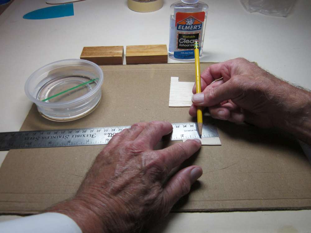
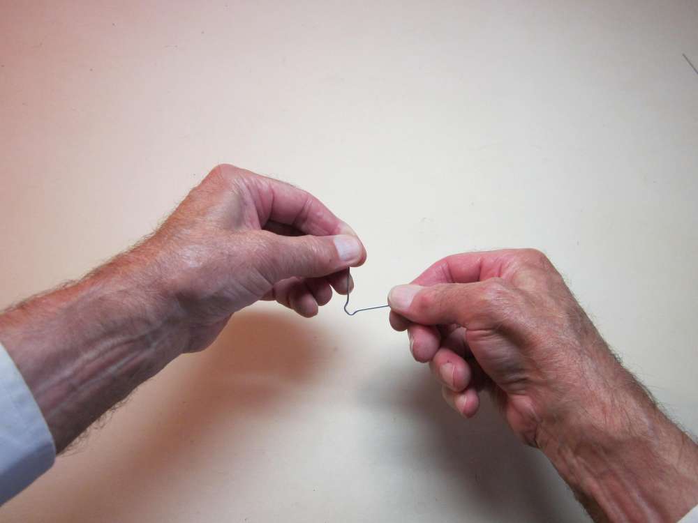
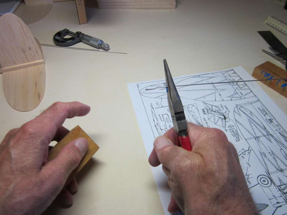
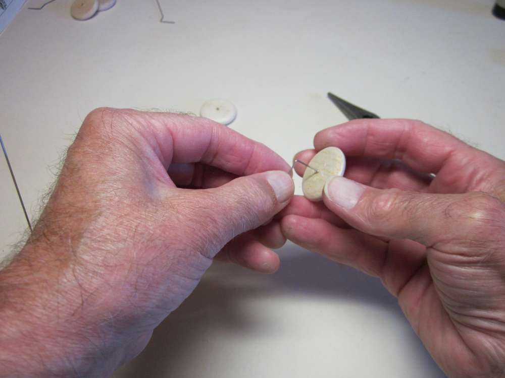
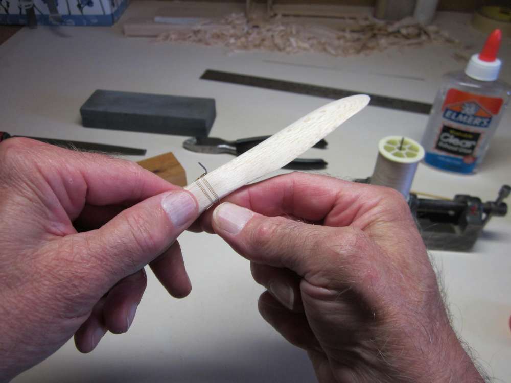
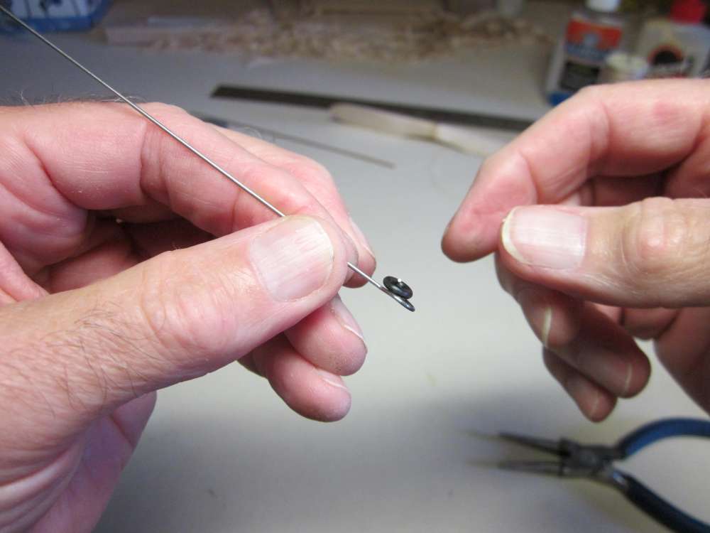
To make the rudder adjustable, we will connect it to the fin with three pieces of bendable iron wire. We want the rudder to bend to the right, so we will glue the wires to the right sides of the fin and rudder. Mark the hinge line on the right side of the rudder 1/4″, 1″ and 1 3/4″ up from the bottom.
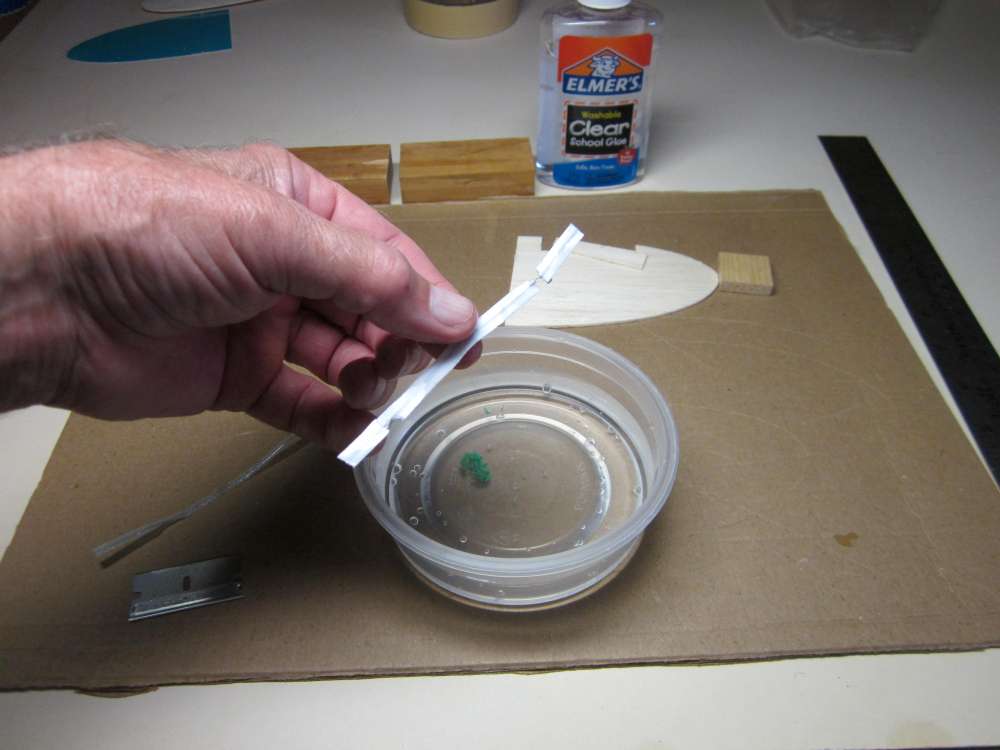
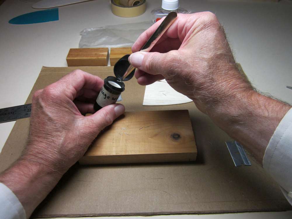
We will get our wire from a vegetable tie.
Soak it in water to remove the paper.
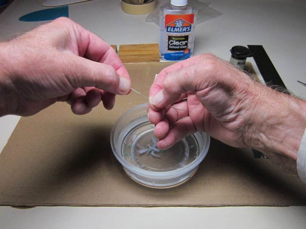
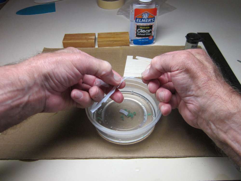
Get all the paper off.
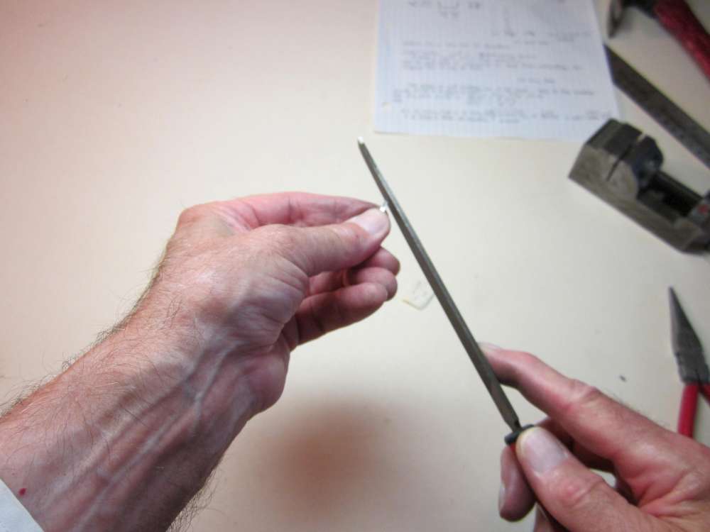
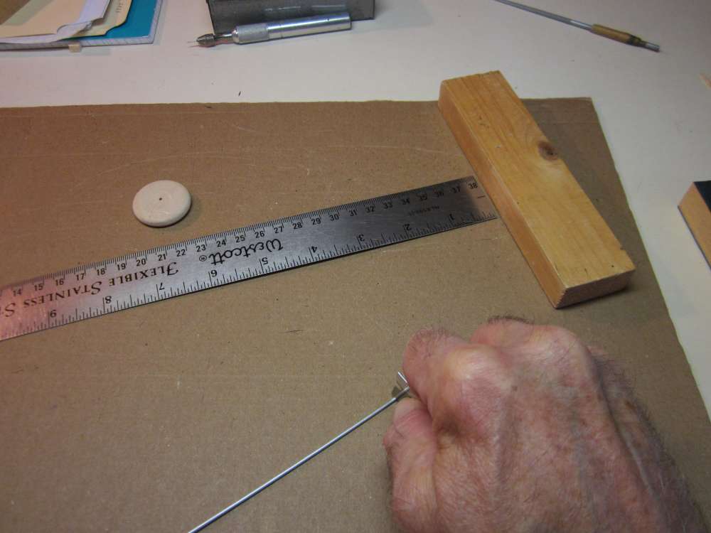
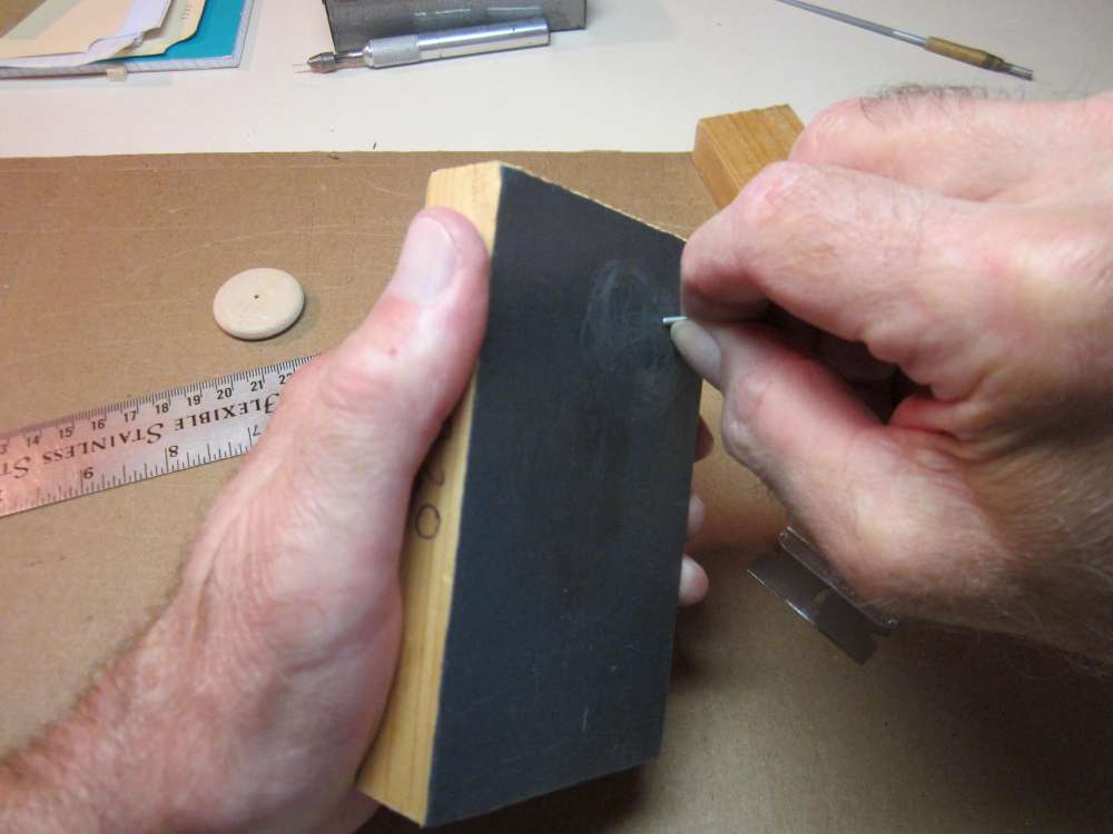
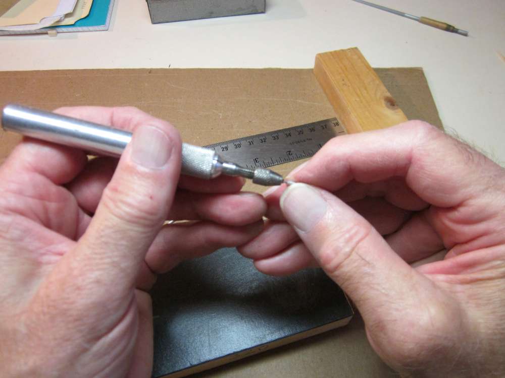
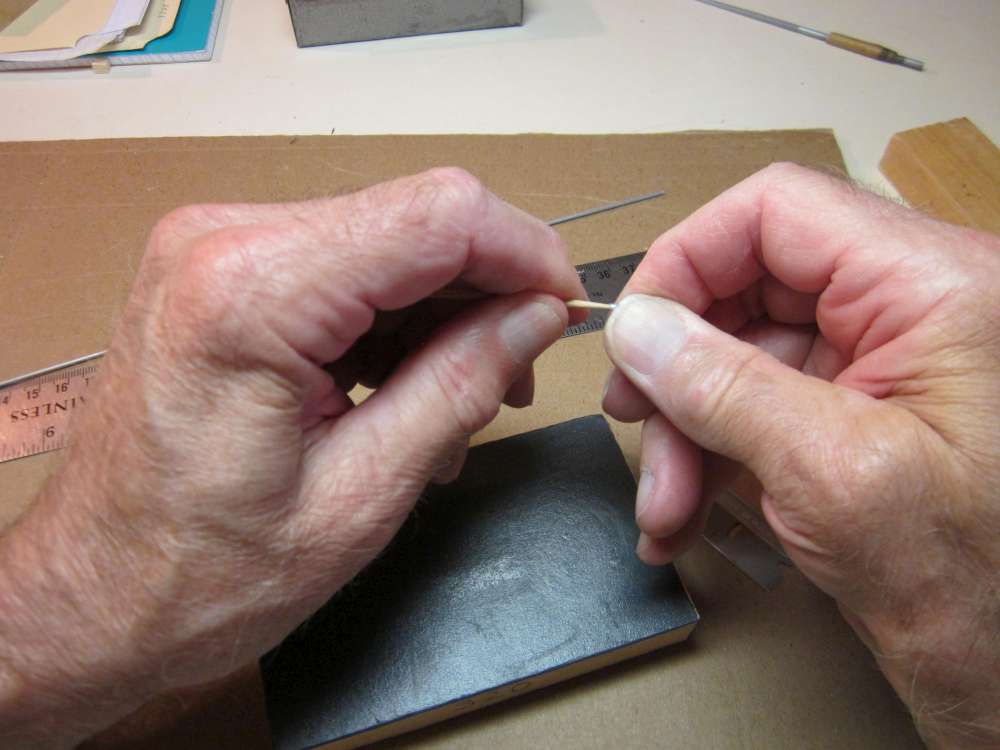
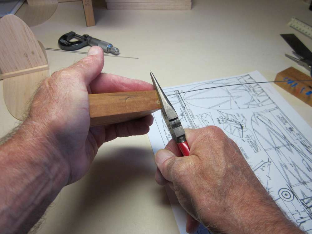
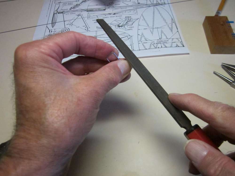
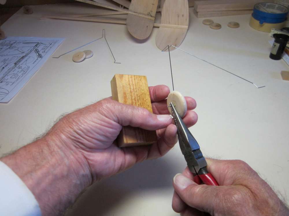
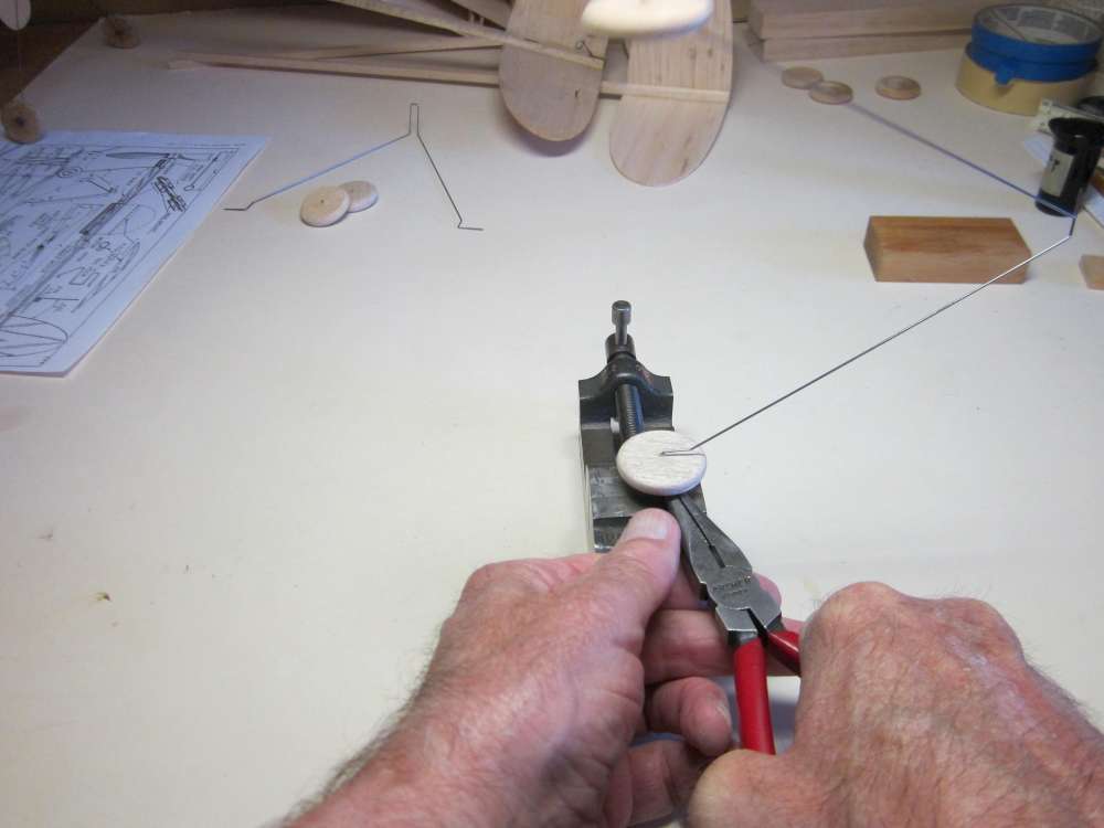
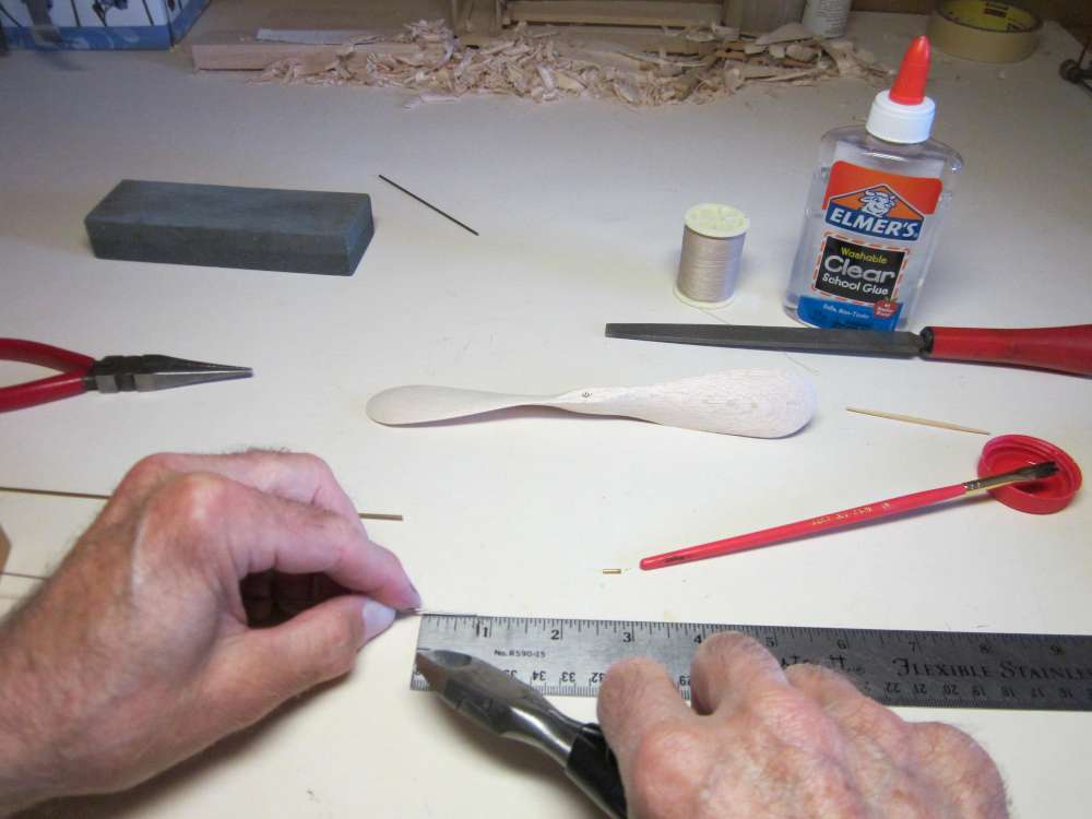
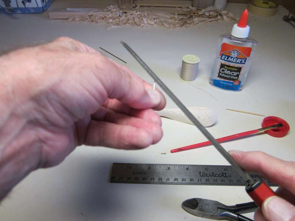
The wire can be straightened by rolling it between two blocks.
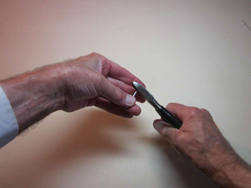
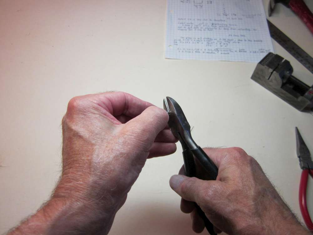
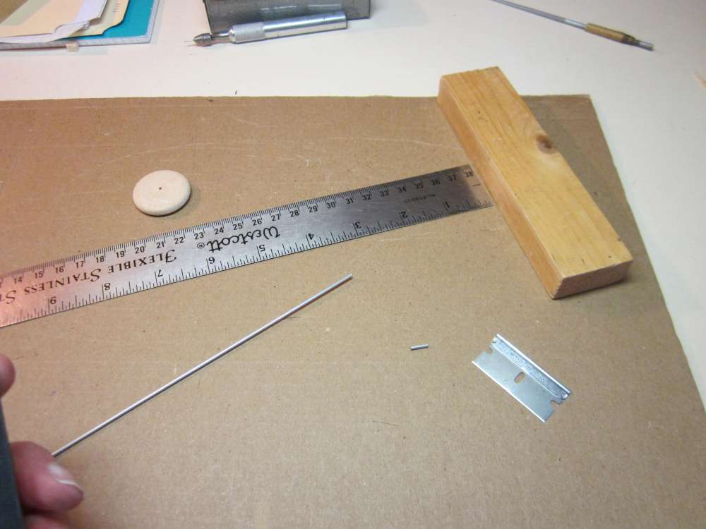
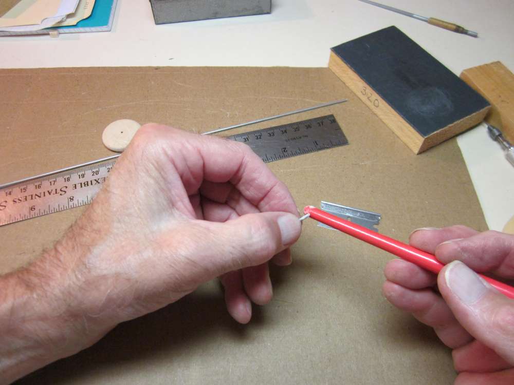
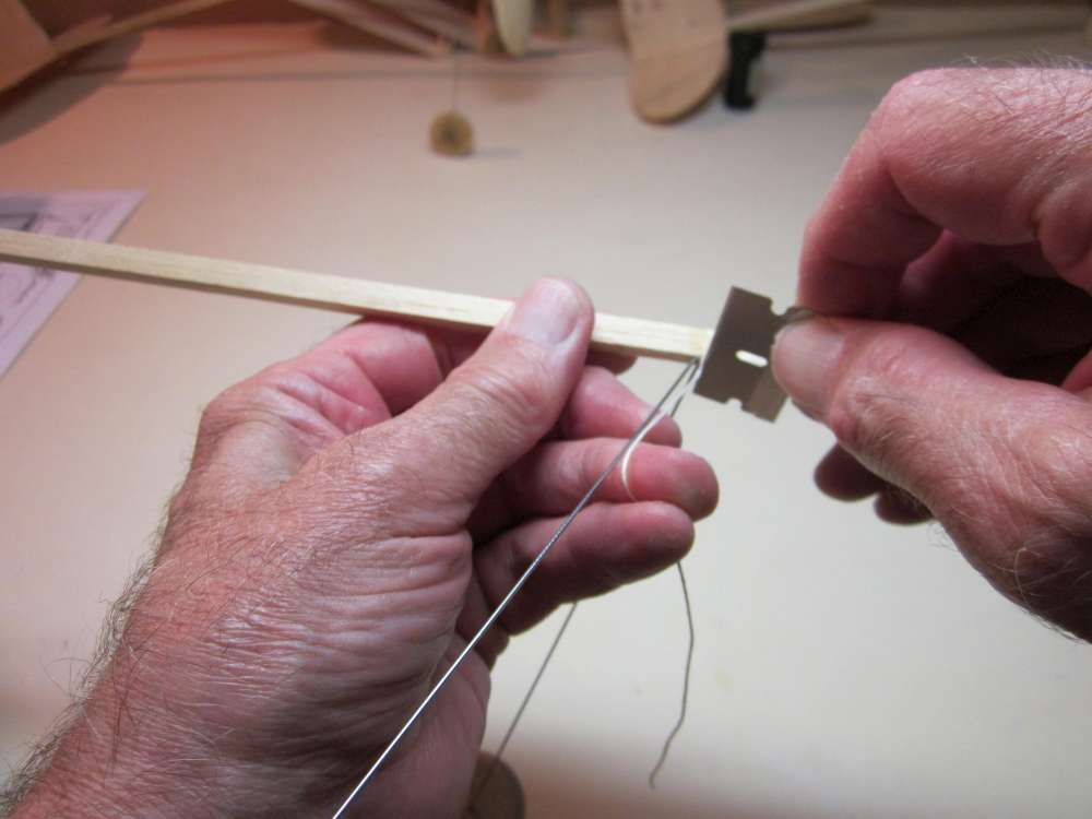
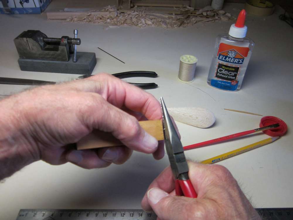
Cut it into 1/4″ lengths. It can be cut by rolling it under a razor blade.
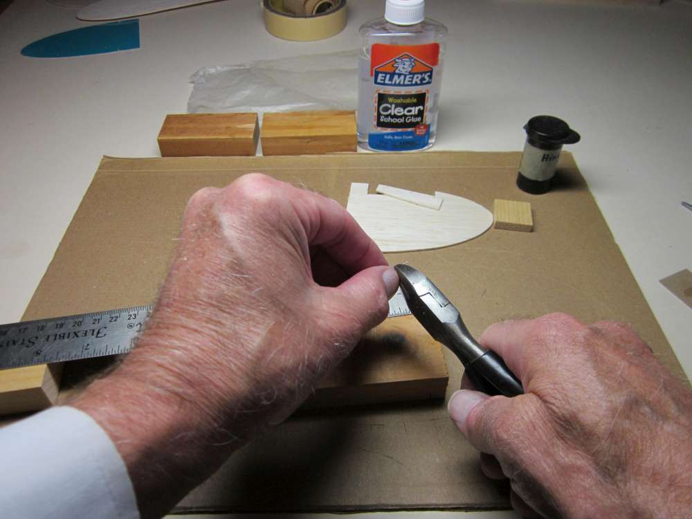
You can cut it with diagonal cutters.
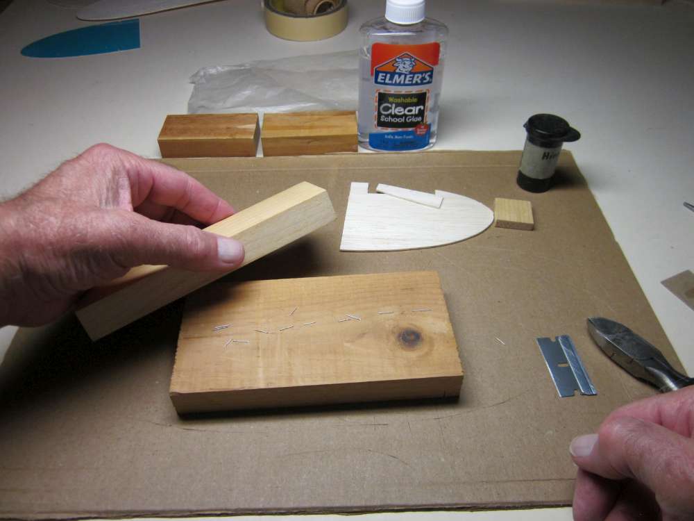
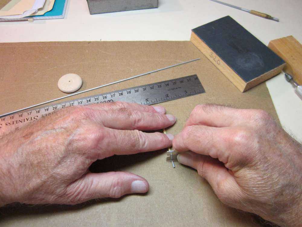
While we are at it, we may as well cut a bunch of them for use later. If these have gotten bent, straighten them by rolling between blocks.
We need only three, so store the others for other airplanes later.
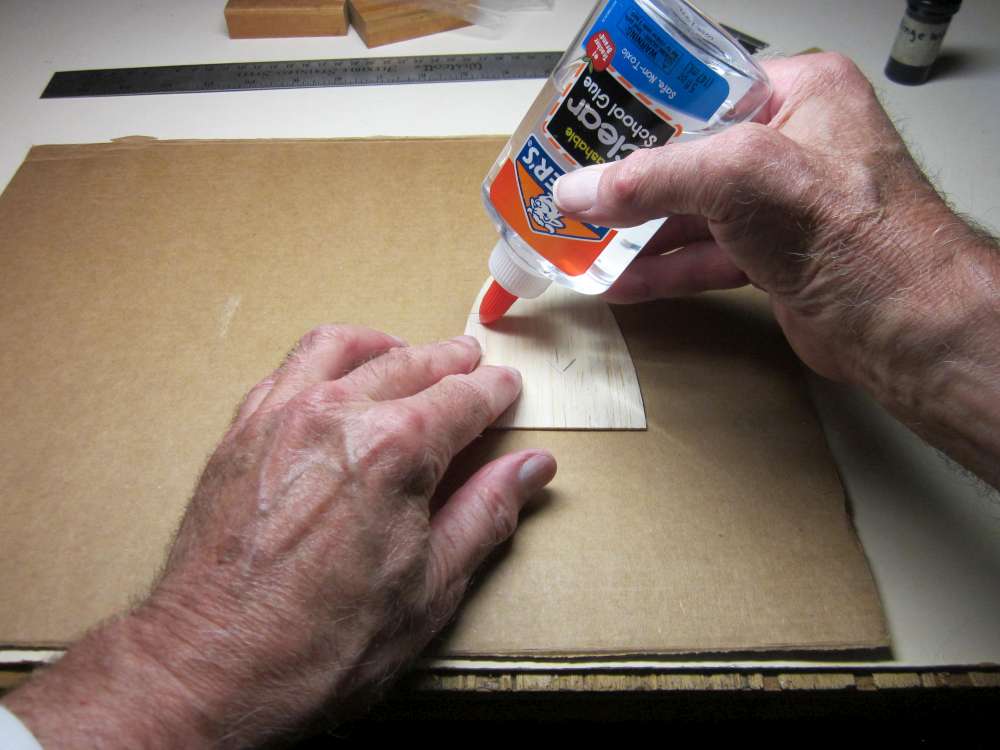
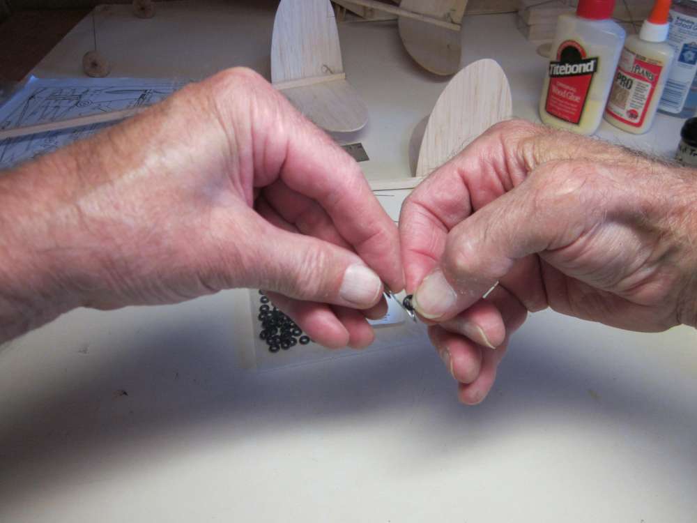
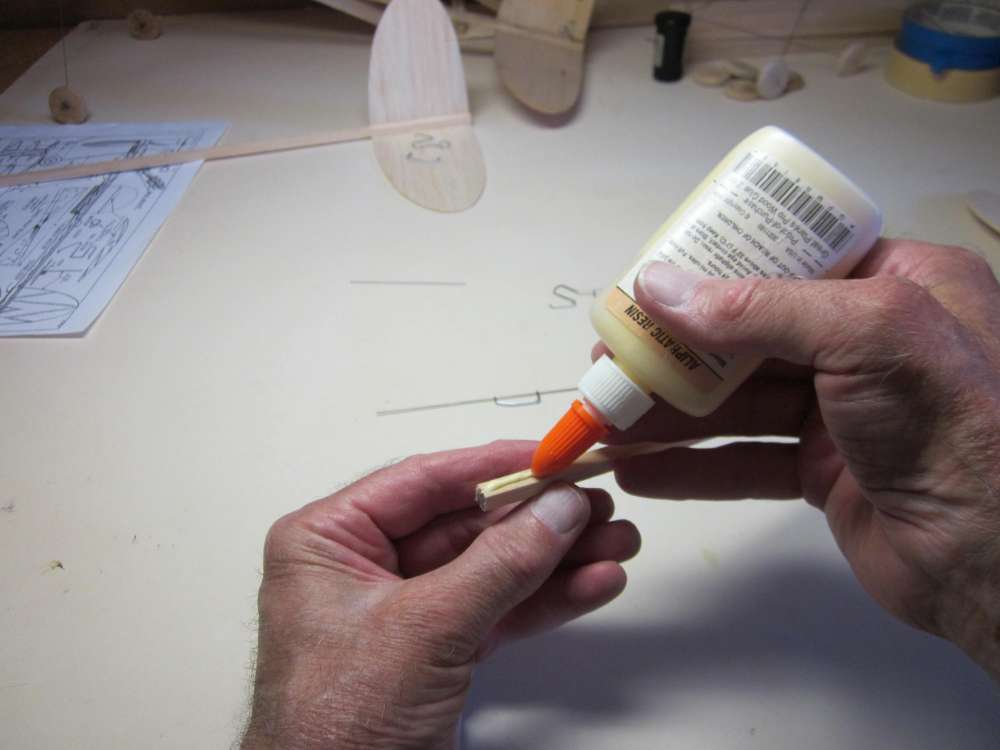
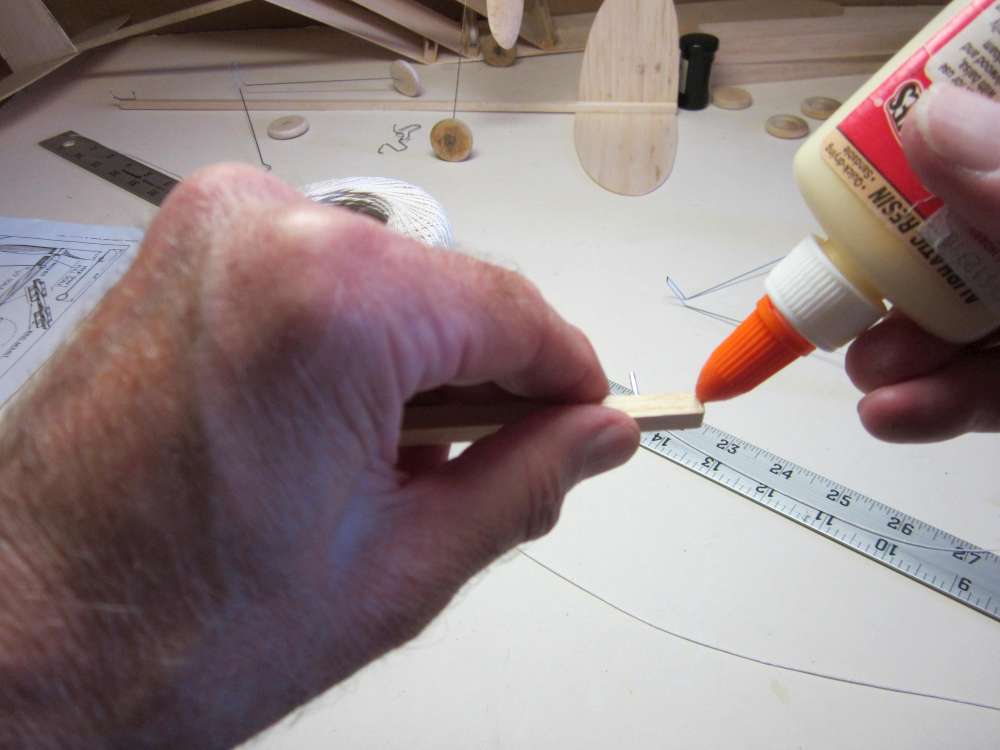
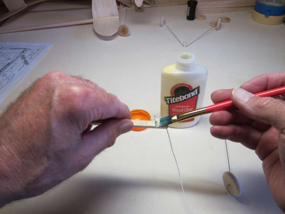
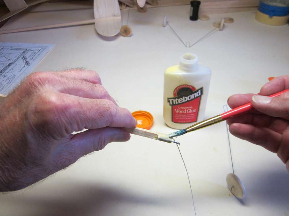
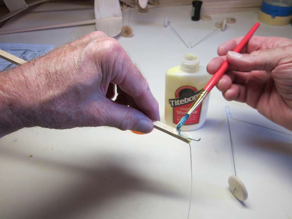
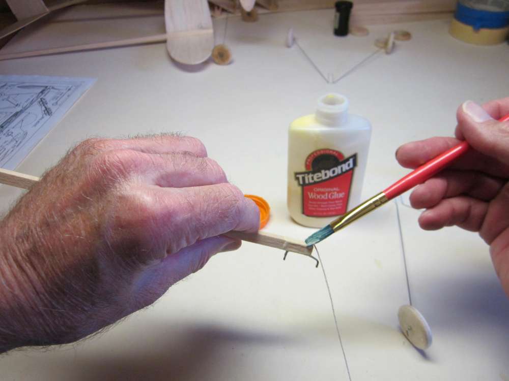
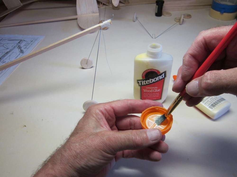
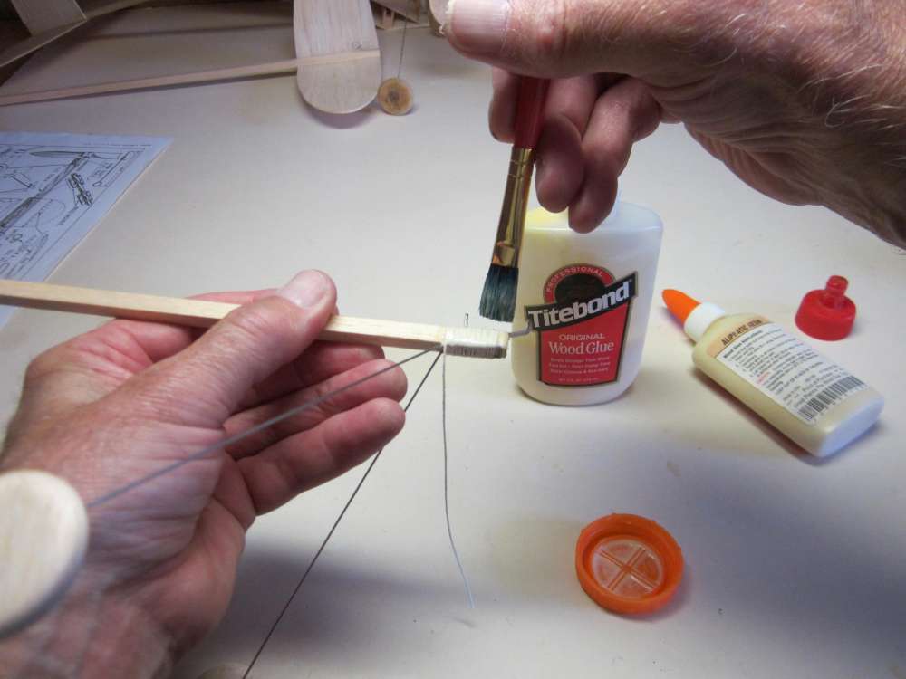
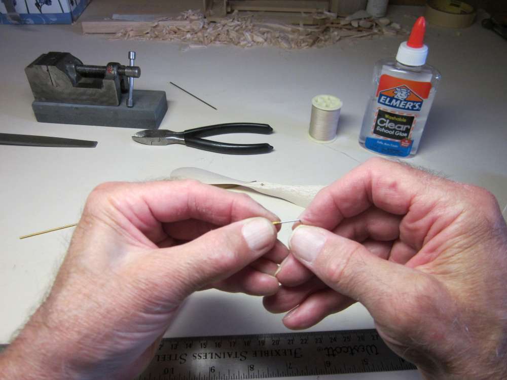
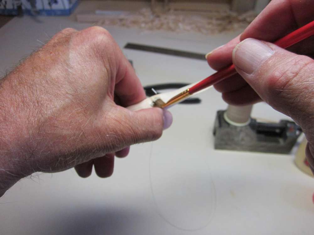
Draw a 1/4″ long glue line perpendicular to and across the hinge line, centered on it.
Place a piece of the wire in the glue line.
Work it back and forth to be sure it is completely immersed in the glue. Repeat for the other two wires and let the glue dry.
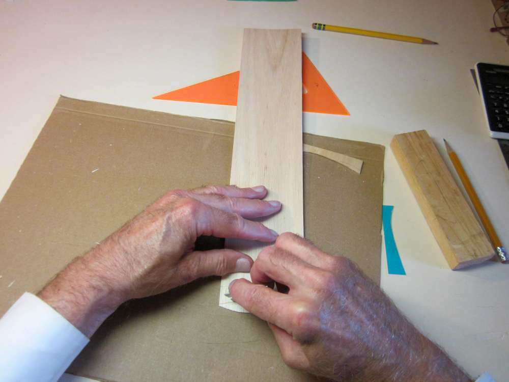
THE STICK
The fuselage is made from a 1/4″ x 1/4″ x 36″ balsa stick. On my first Cloud Tramp I used a stick of 6# density balsa to keep the weight low. This turned out to be too soft. It was bent by the tension in the rubber motor, causing the plane to nose up into a stall. I replaced it with a stick of 9# density, which has worked well. This would have been from a 36″ stick weighing 5.32 grams. The sticks in kits have weighed considerably more, made from 12# to 14# balsa.
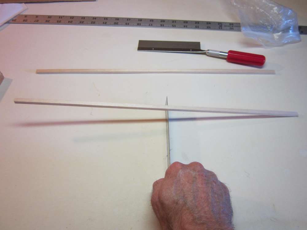
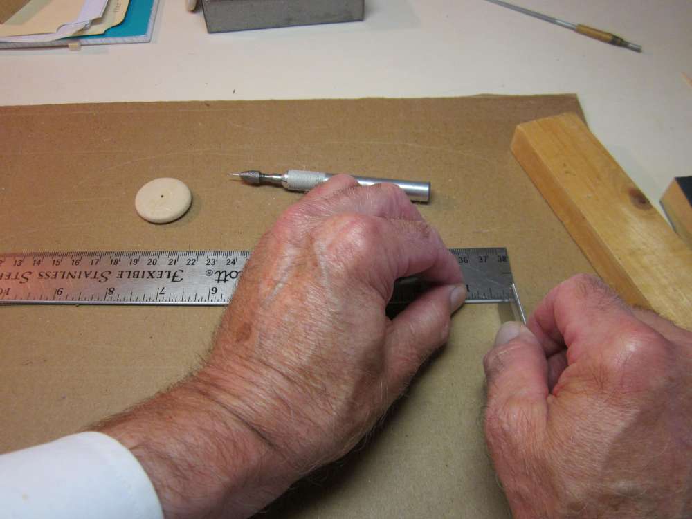
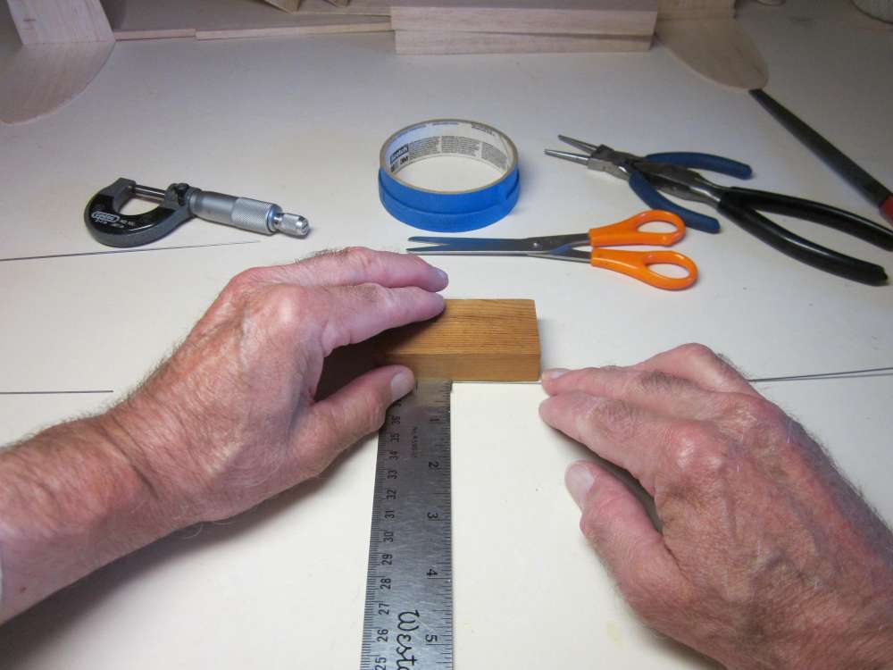
Mark off an 18″ length on your stick.
Cut the stick to length.
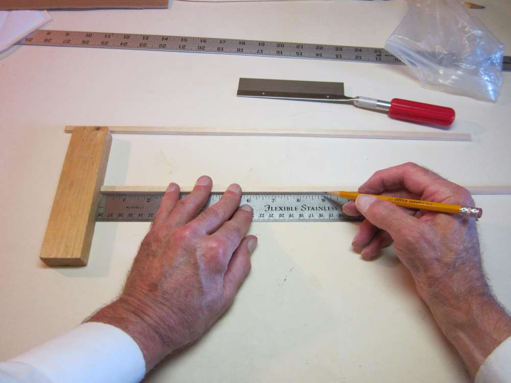
Mark the center of this stick at 9″.
Balance the stick on the edge of the straightedge. Note which end goes down. This is the heavy end and we want it to be the front end of the fuselage.
Mark the heavy end of the stick
THE WING MOUNT SIDE PLATES
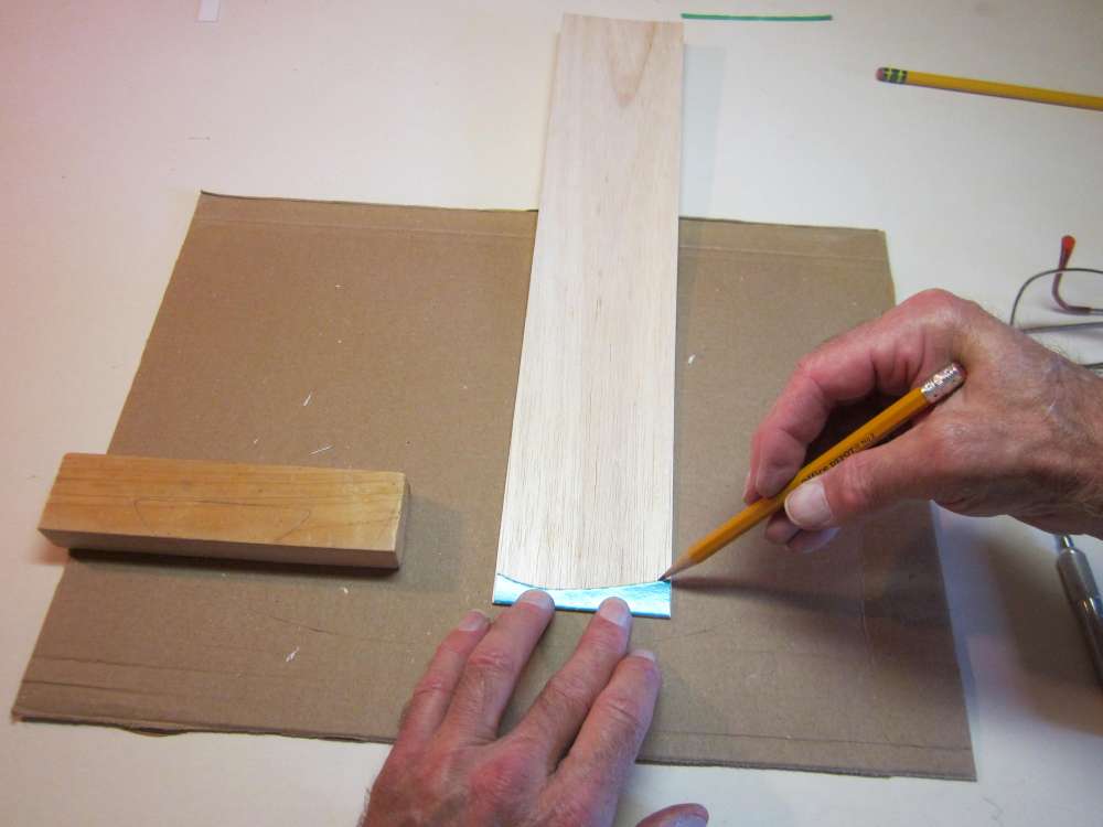
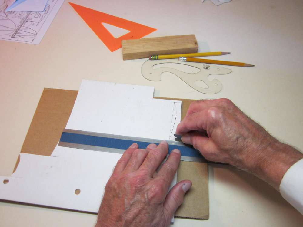
Place the straight edge of the side plate against the square end of the balsa sheet and mark the curve. The grain will run across the short width of the plate to best resist the forces which will try to bend this plate. Note that the pattern is 1/16″ shorter than the width of the sheet, so 1/16″must be marked to be cut from the end. I didn’t simply cut this out because it is hard to cut along a concave curve without cutting into the pattern.
Carefully cut along the pencil lines. Again we are cutting across grain. Do not cut going off the edge, cut into the wood at the edge. Otherwise the wood will split away at the edge. Don’t forget to cut off the extra 1/16″ of length.
We need two side plates. Use the block and triangle to get the pattern square to the edge and mark the balsa along the curved edge.
Mark along the end where the extra 1/16″is cut off.
Without moving the triangle, mark the straight edge of the side plate.
Cut along the curve, as before. And then cut the straight edge, using the steel rule to guide the blade.
THE PROPELLER BEARING
Each of the referenced kits has a different way to mount the propeller shaft to the stick. The original plan shows an L shaped bearing, made from a 3/32″ cotter pin, with a single hole for the 1/32″ steel shaft. I found that this let the prop wander around, making for an erratic flight path. I fixed this by bending up the back end of the cotter pin and adding a second hole for the shaft. I also found that the 1/32″ steel prop shaft bent easily. I was constantly having to bend them straight and replace them. George Bredehoft is using a Peck shaft of 0.045″ steel wire for that reason. His full kit included the appropriate Peck nose button and plastic prop. His wood prop blank has a 1/16″ diameter hole. The Vintage Model Company kit includes an 0.047″ steel prop shaft, an appropriate plastic nose button and plastic prop. I replaced my shaft with 0.055″ steel wire, but now the shaft will not fit inside the 0.032″ inside diameter brass tube prop hubs I was using. I’ve had to remove the brass tube hubs and run the prop shaft through balsa wood. I hardened the inside of the hole with a good soaking of glue. So you have several options, depending on your goals.
I am going to show you how I made a two hole bearing from a 3/32″ cotter pin and used a 1/32″ steel wire shaft and a 1/16″ brass tube hub.
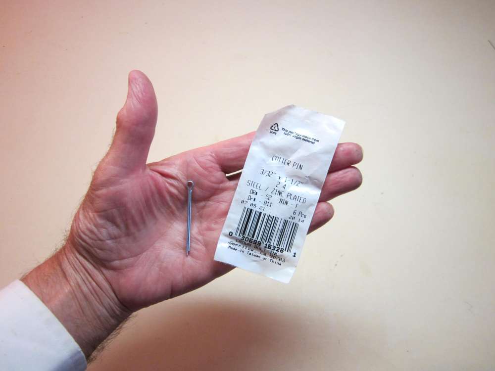
Per the original instructions, the prop shaft bearing is made from a 3/32″ cotter pin.
First open the pin and flatten it.
Cut off the excess at the bend.
File off the sharp edges and round the corners.
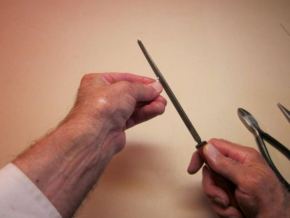
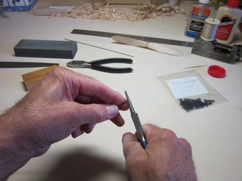
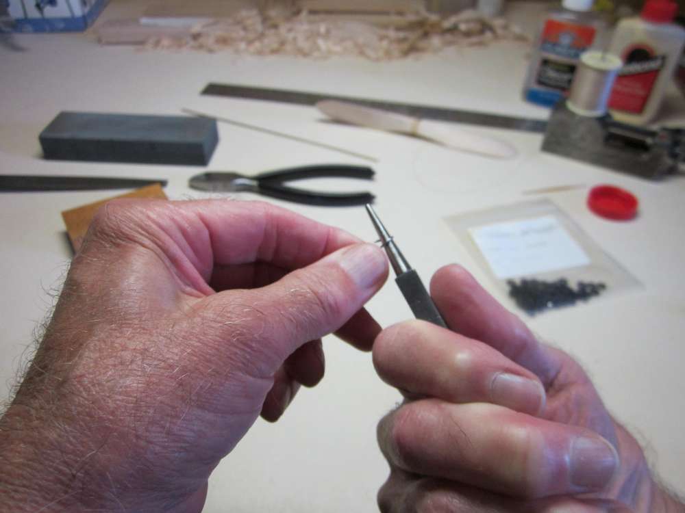
I filed a 90 degree point in a 1″ length of 0.045″ steel wire and used it to punch a starter hole for the drill, 1/16″ from the end. This punch bent after a while. 1/16″ wire is recommended.
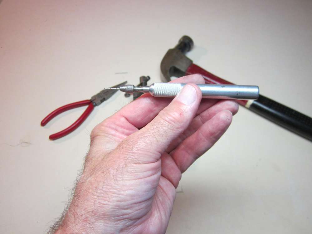
I am using a No. 64 (0.036″) drill in a pin vise.
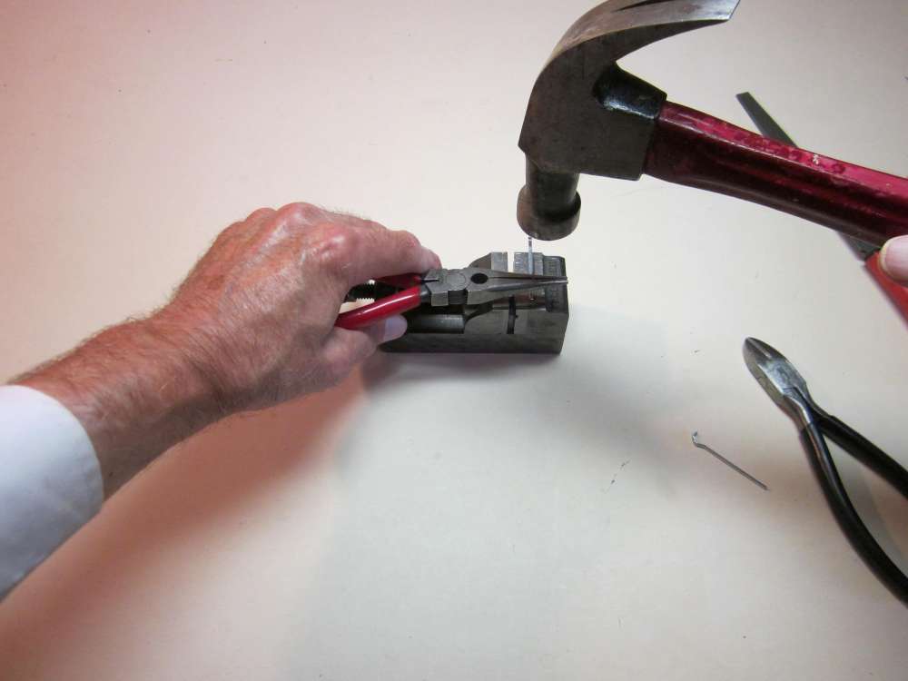
With the cotter pin held in the vise, drill the hole all the way through.
Clean up any burr.
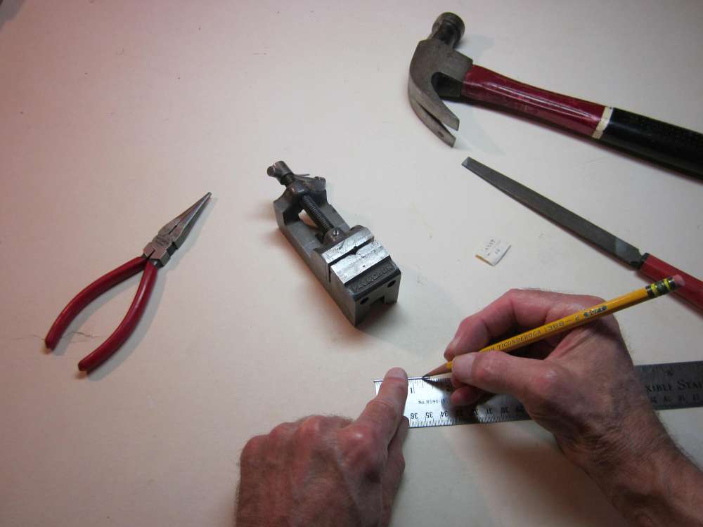
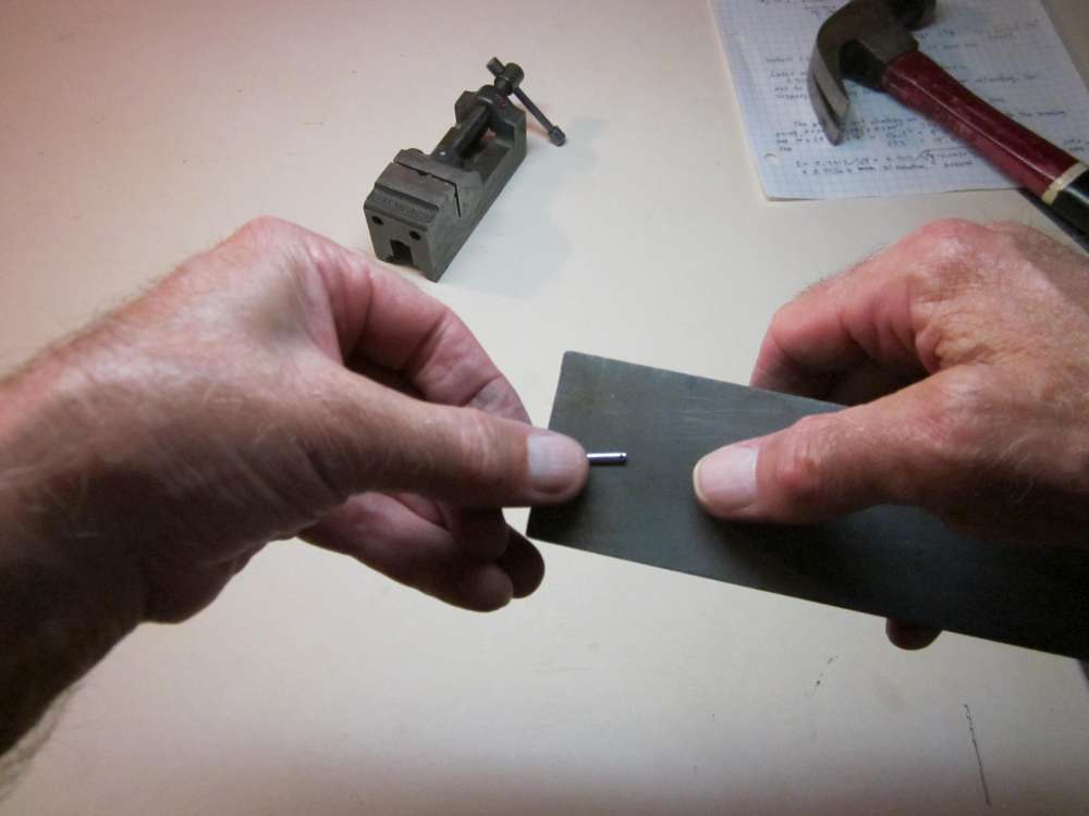
When the first hole is done, measure 1 1/4″ from there and mark the location of the second hole.
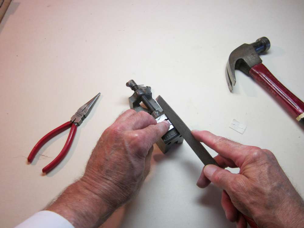
You can also file a notch across the round side of the cotter pin with the edge of a file to locate the drill hole. A smaller file could be used.
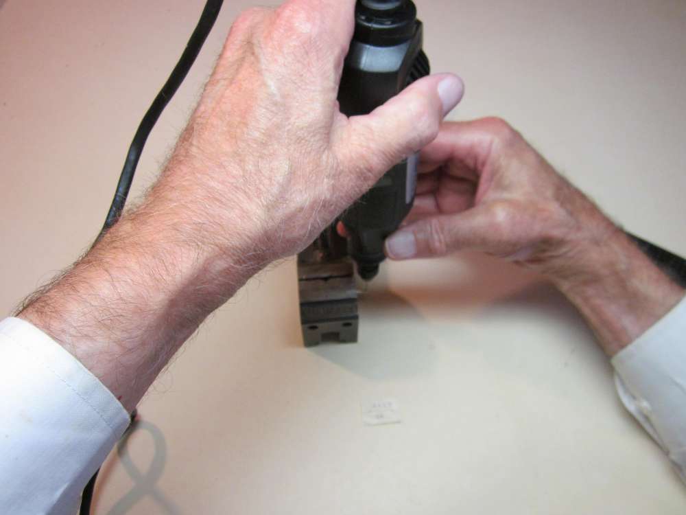
You can also use a Dremel tool to turn the drill.
File off any sharp spots and round the corners.
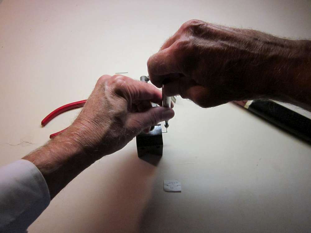
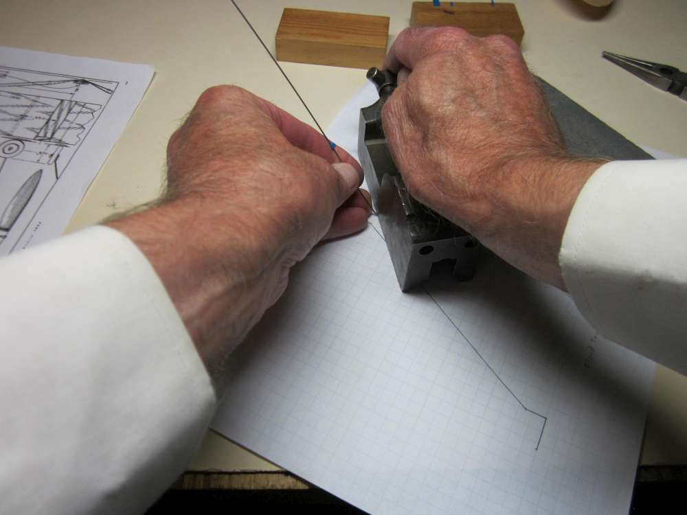
We want the hole to be 1/4″ up from the top of the stick when the bottom of the bearing rests on the stick. If we grab the cotter pin with the pliers at a certain mark and bend in a right angle, the flat surface of the bent piece will be 1/16″ away from the face of the pliers. (Try it yourself.) Make a mark 1/4″ from the end of the Cotter pin.
Put the mark at the face of the pliers.
Bend with the round face on the inside to a right angle. If you want to make an L shaped, single hole bearing, as on the original plan, you may cut the base leg off to make an overall length of 1″, file off the sharp edges, round the corners and you are done.

Make a mark 1/2″ over from the bent up end.
Bend the end up to about a 30 degree angle above the flat bottom.
Grab the end with the face of the pliers 1/8″ in from the end and bend this part about 60 degrees more.
Thread a piece of 1/32″ steel wire through the holes to check that the wire is exactly parallel with the base. Adjust the bends as necessary.
That additional shallow bend allows adjustment of shaft parallelism and it also puts the prop farther away from the stick so the trailing edge of the prop won’t hit the end of the stick.
Just a double check that the shaft is 1/4″ away from the base of the bearing. This spacing is necessary to prevent knots in the motor jamming against the stick.
WHEELS
The original plan and instructions call for 1/4″ x 1 1/4″ hardwood wheels. At that time, hardwood wheels were a standard hobby shop item. That is no longer the case. George Bredehoft’s short kit includes laser cut balsa disks from which you make your wheels. The Vintage Model Company kit includes lightweight plastic wheels.
Guillows Replacement parts page includes 1 1/4″ hardwood wheels, but they are sold individually at $3.00 each. You will need two of them.
https://www.guillow.com/1woodwheel.aspx
Guillows does not list them on their Bagged Parts & Accessories page, where the unit prices are lower than the individual prices. If you contact Guillows Customer Service, they may provide you with a set of wheels at a lower price. Guillows has a minimum order of $10.00. Look around their site and see what else you might like to pad your order. Get together with friends to make a larger joint order.
Let’s get started making our own wheels. These instructions can also be used to make the wheels from George’s short kit.
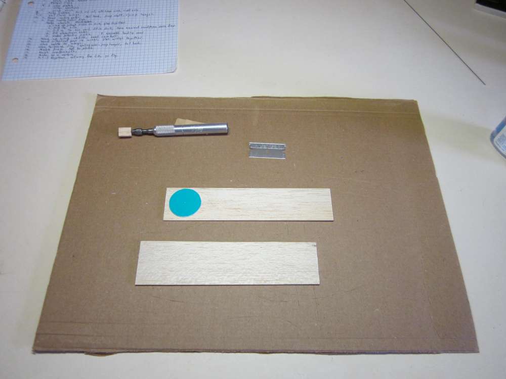
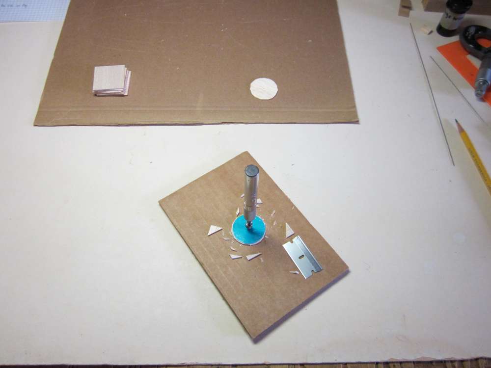
Find some 1/16″ balsa sheet. These pieces came out of my scrap box. You will need enough to make 8 wheel disks.
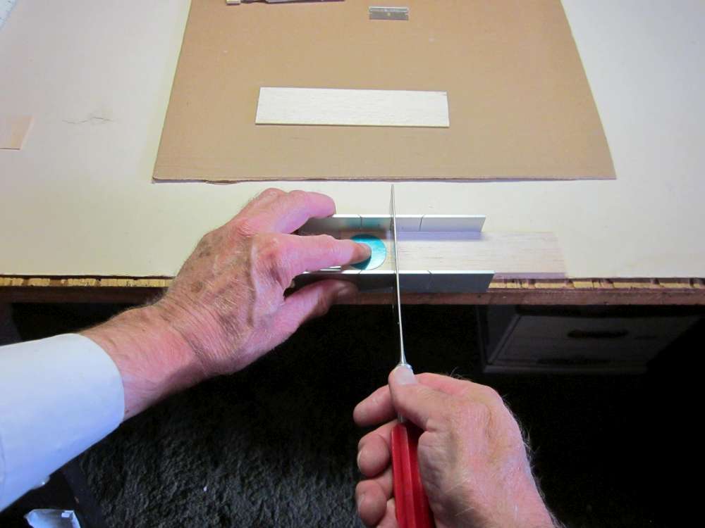
Cut the wood into squares a little bigger than the wheel.
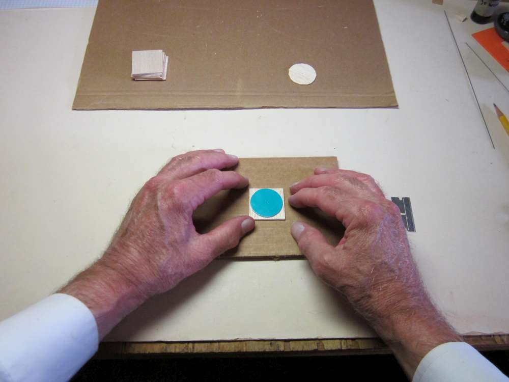
Center the wheel pattern over the balsa square.
I used a pin vice, but a pin would work as well.
Pin the pattern and balsa to the board.
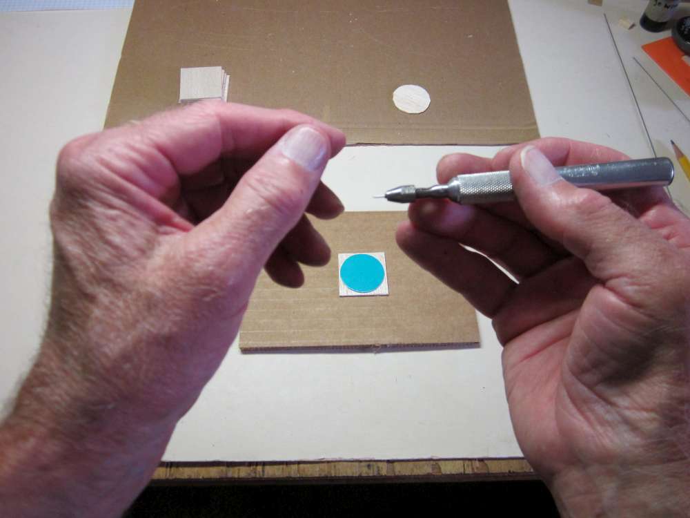
Cut the excess wood away around the wheel pattern. Cut as close as you can, but don’t undercut inside the pattern.
Leave a little bit of balsa outside the pattern, as much as 1/32″ is OK. The excess will be sanded down later.

Remove the balsa disk from the pin.
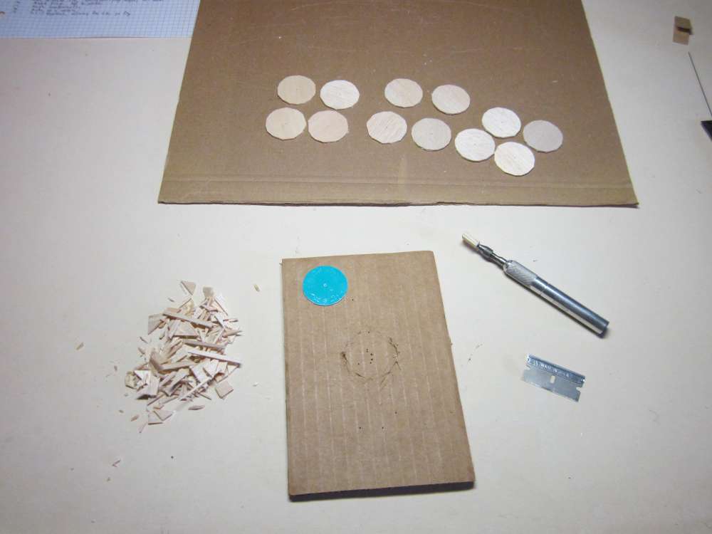
Keep going until you have enough disks to make the wheels you want, 8 disks are required to make 2 wheels.
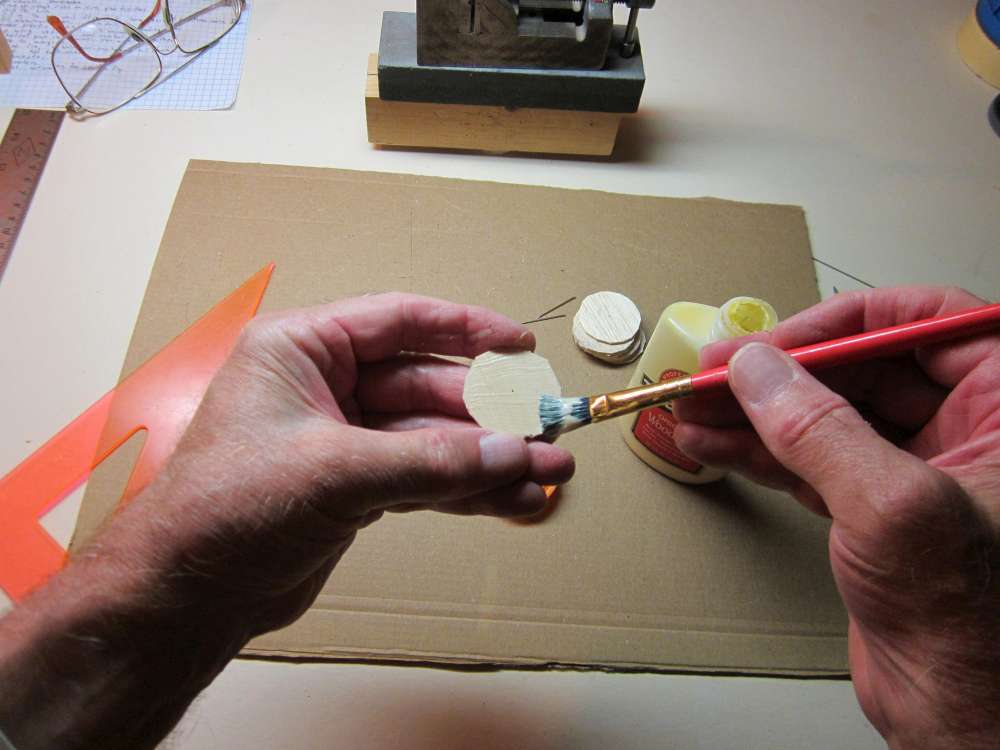
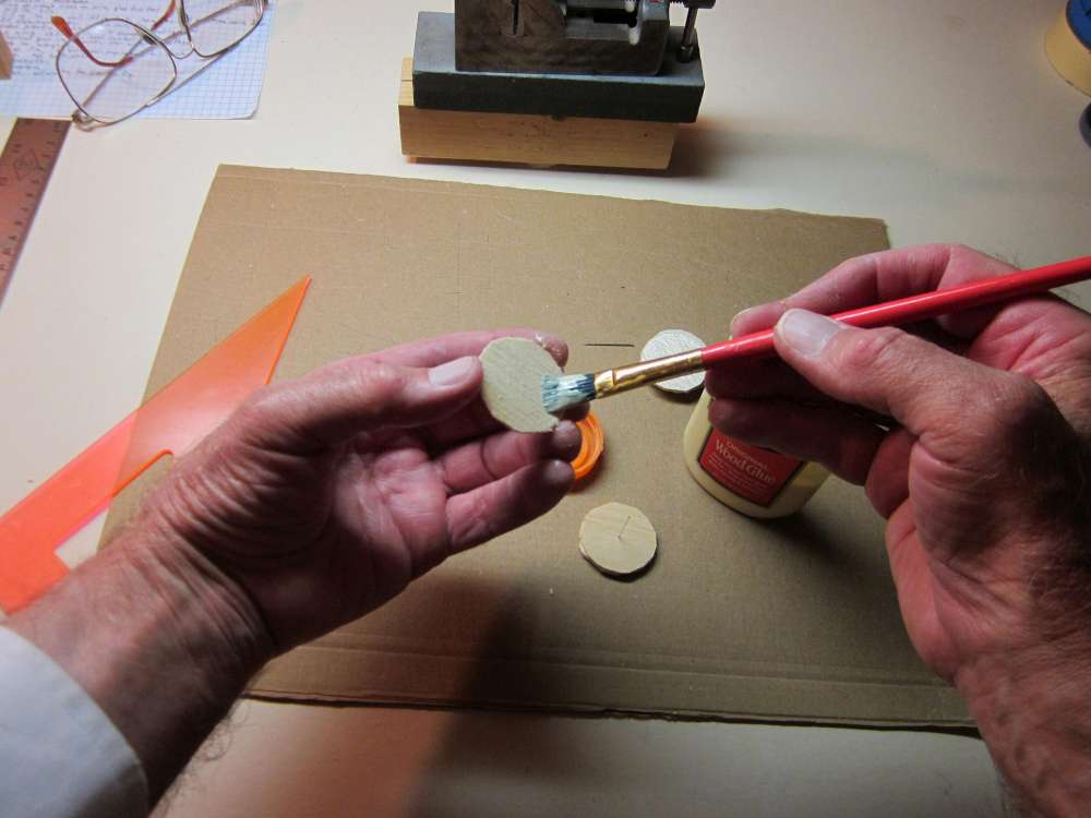
Paint a thin layer of glue on a disk, just enough to glisten, but thin enough to see wood grain.
Push a pin through the disk from the opposite side.
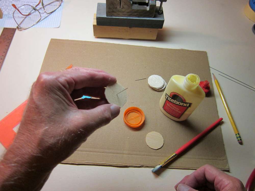
Paint glue on the next disk.
Put the pin through the pinhole in the second disk. Keep the disks perpendicular with the pin. Cross the grain of the two disks.
Continue laminating until you have four layers. Squeeze them together tightly. Make sure the pin is perpendicular with the disks.
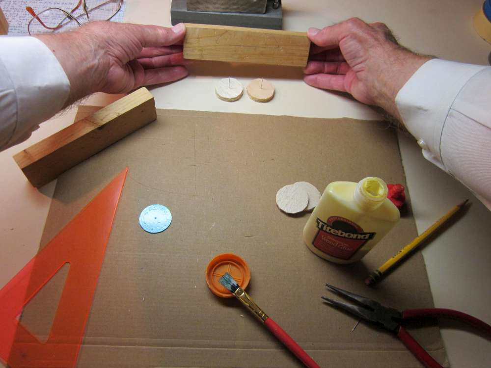
Place the wheels down on the board with the pinheads down.
Place blocks on either side of the pins.
Place weights on top of the blocks to clamp the disks together. Leave it until the glue is dry.
After the glue has had time to dry thoroughly, remove the weights and blocks.
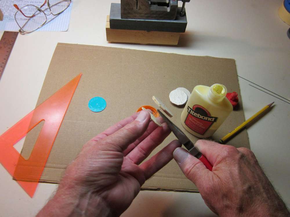
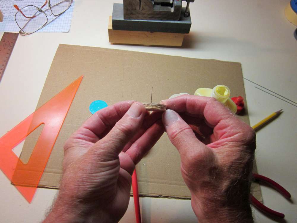
Push the pins out of the wheels. You may need to rotate the pins with pliers to break the glue joint.
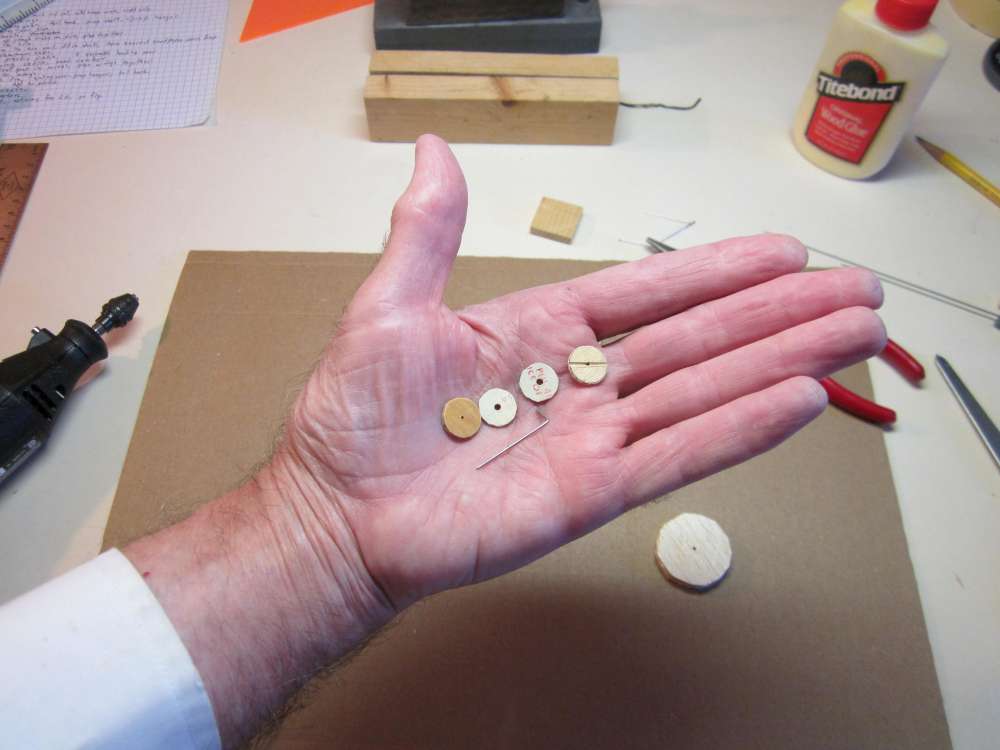
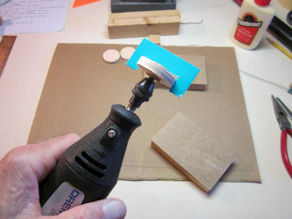
Now we get ready to turn the wheels round. The wheels must be clamped on a shaft which is put in a chuck. They are clamped between disks. The disks are about 1/2″ in diameter. There are two of 1/16″ plywood with a 1/32″ hole through the center, one of which has a groove filed across a diameter. There are two made from wide rubber bands found in the grocery store produce section. (Broccoli, asparagus.) The holes may be punched with a leather punch. They don’t need to be a tight fit on the wire shaft. There is also a 1/32″ steel wire shaft with about 1/4″ bent over at one end.
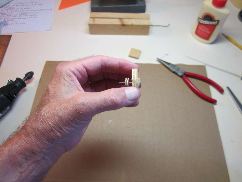
Everything is threaded onto the shaft, first the ply disk with the slot against the bent over end, then a rubber disk, then the wheel, then the other rubber disk, then the other ply disk.
The bent over end engages the slot.
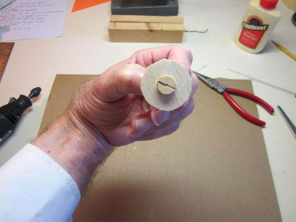
Put the shaft into the check and snug it down lightly.
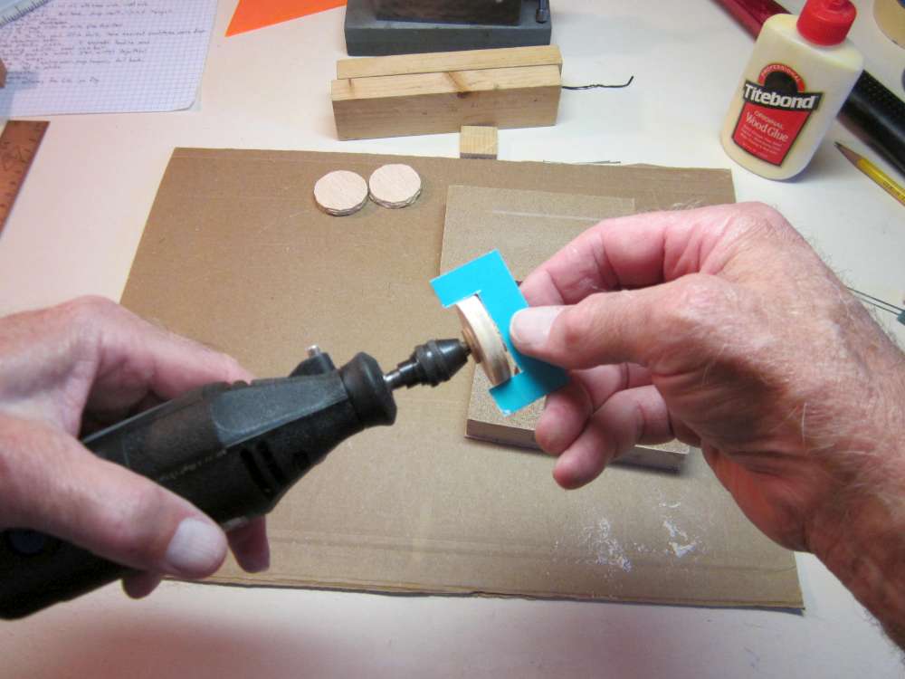
Tap it in tightly to compress the rubber disks.

Tighten the chuck as much as you can.
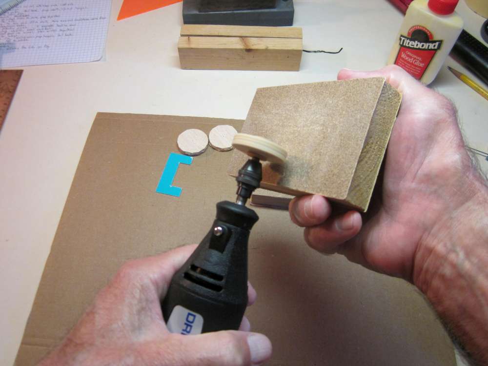
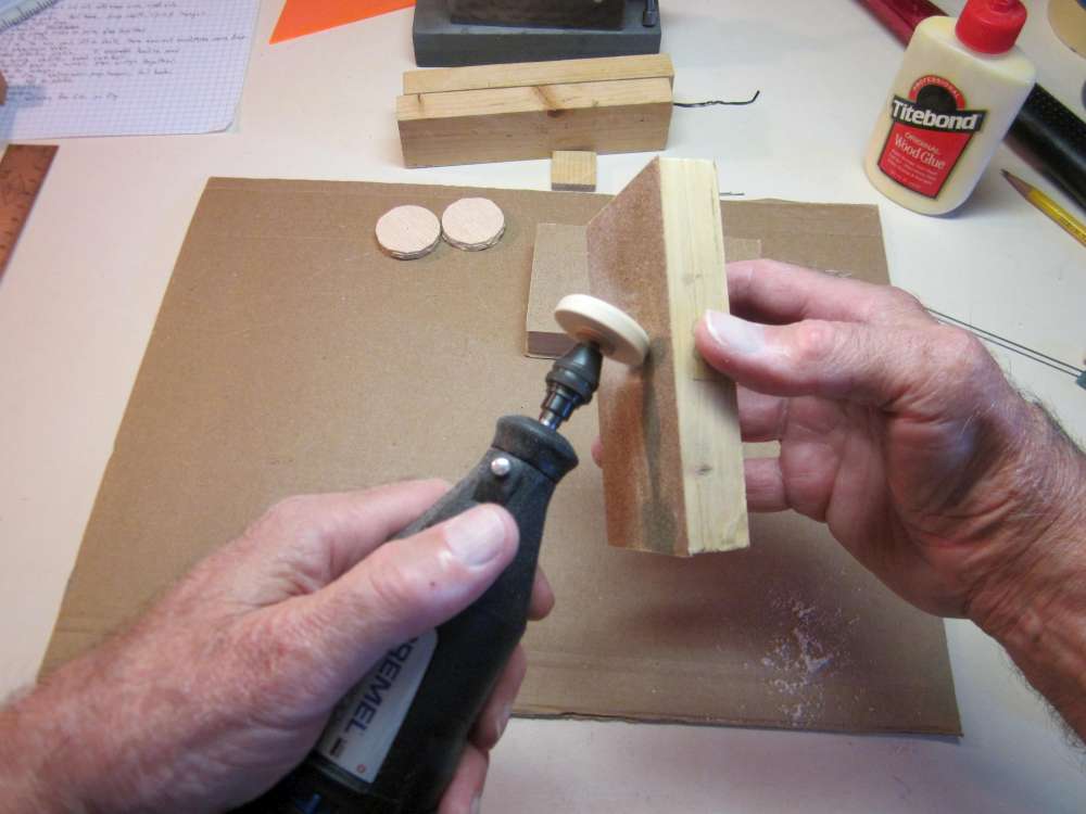
Using coarse sandpaper on a block, round the wheel straight across. Use a light touch, the wheel is rough at first. We just want to get it uniform.
Occasionally check the wheel diameter. If the gauge gets hung up, it is not done. As it gets closer to the diameter, check more often.
When it passes with just slight friction, it is done.
Now round off the corners. You can make round tyres or you can leave a flat center and file groves to make tread. Don’t sand away any of the outer diameter in the center. You can break off a emery board at an angle and use it to cut into the surfaces to form the inside edge of the tyre and the hub.
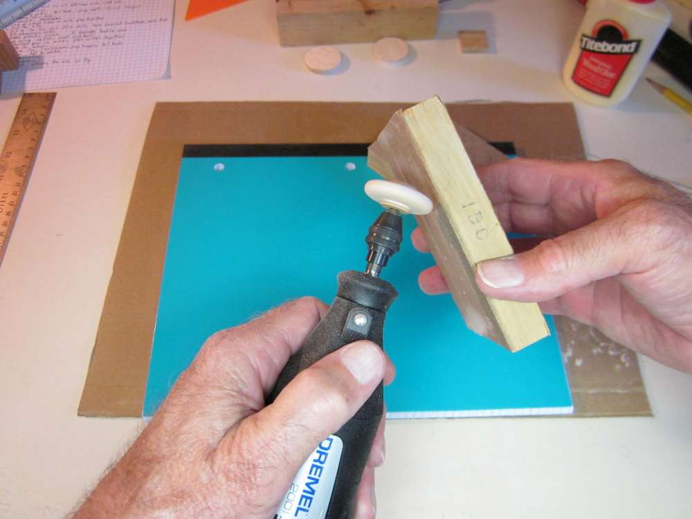
Use fine sandpaper to bring it to final shape. Again, don’t sand away any of the outer diameter.
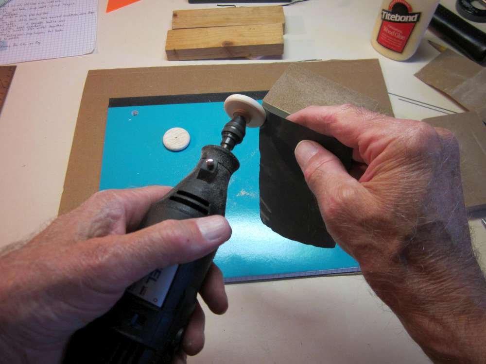
With a light touch of very fine sandpaper, bring it to final finish.
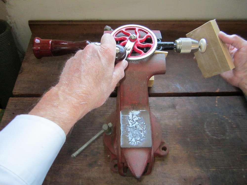
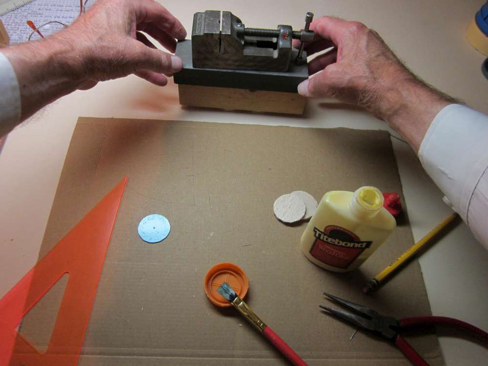
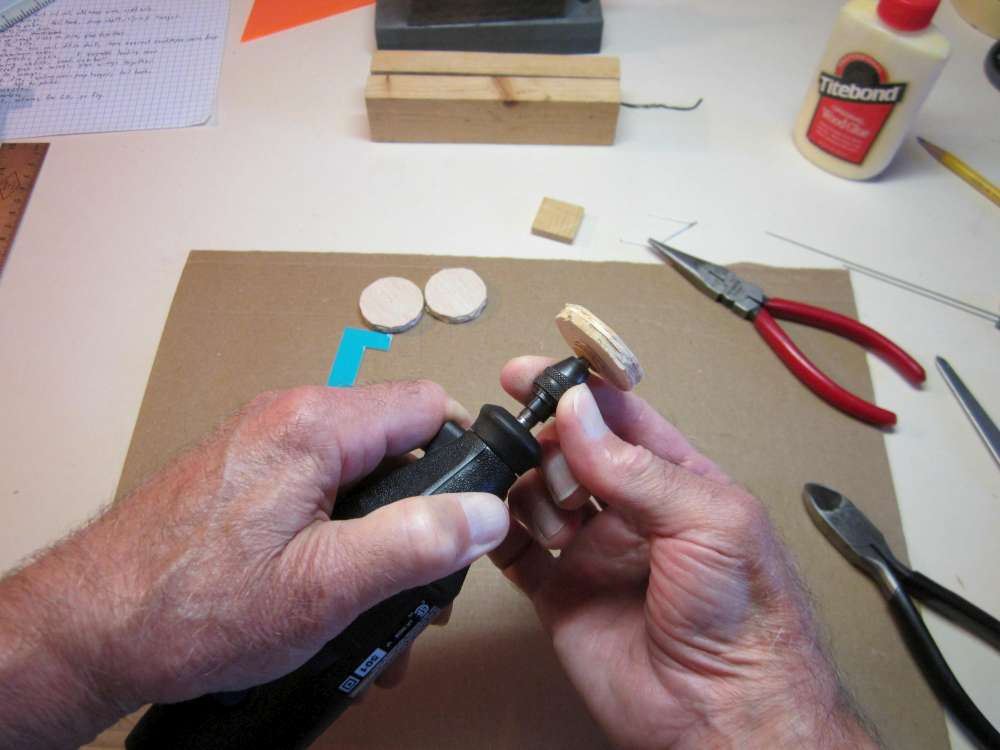
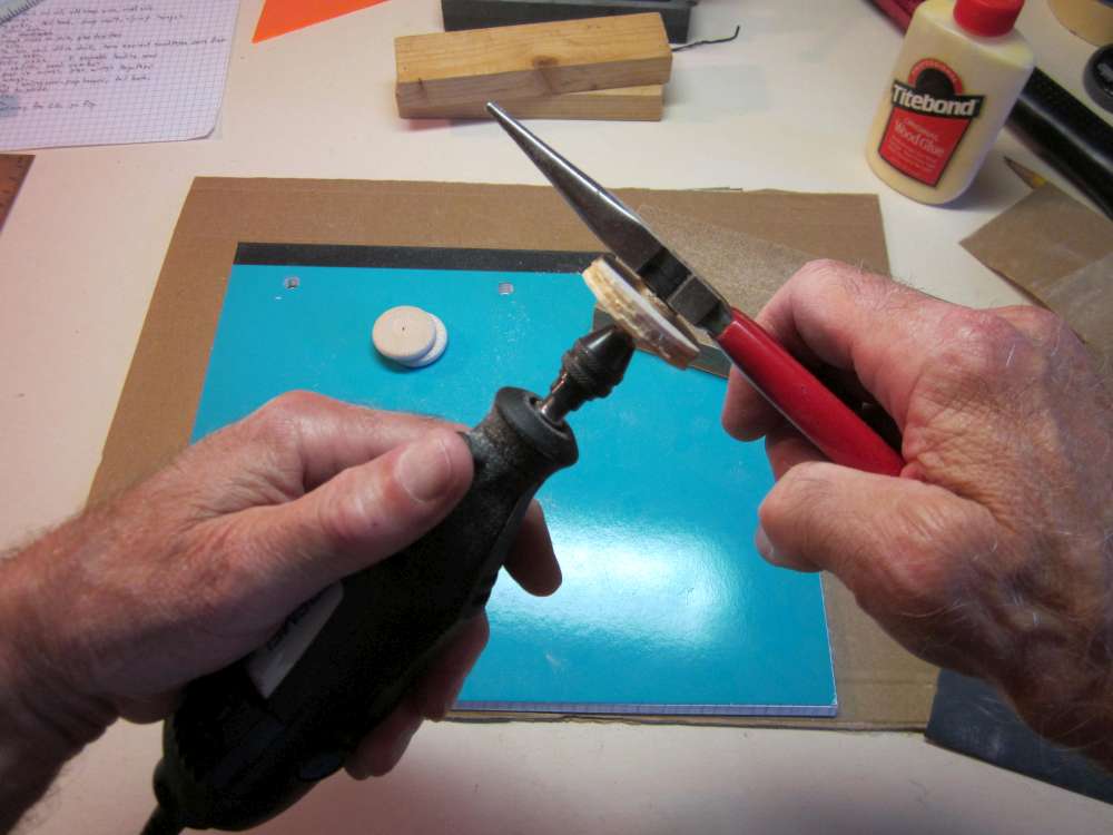
If you don’t have a Dremel tool, you can use an electric hand drill, a drill press, a lathe or a hand drill clamped in a bench vise, as you see here. I have seen good wheels shaped entirely by hand and eye.
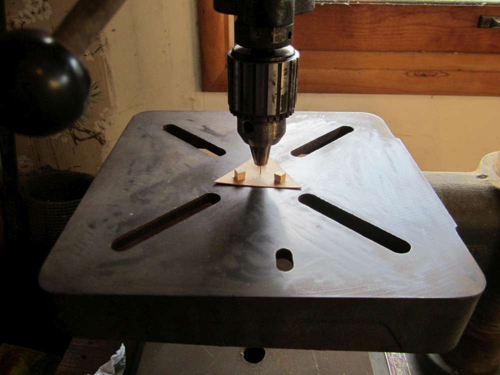
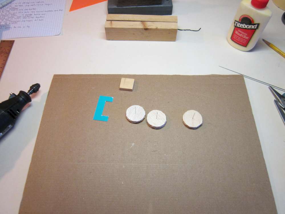
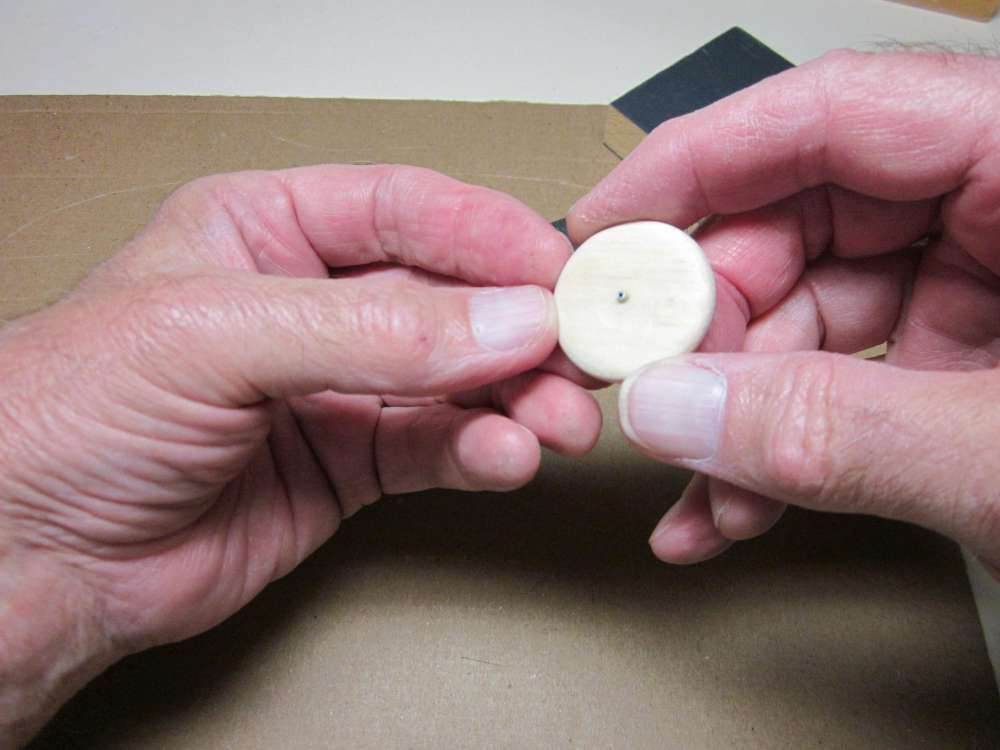
It is necessary to drill 1/16″ holes through the centers of the wheels in order to insert aluminum tube hubs. This is true whether you buy hardwood wheels or make them from balsa disks. To do that we must make a jig to hold the wheels centered under the drill. Start by making a 2 1/2″ equilateral triangle from pattern cardboard. Draw a 1 1/4″ diameter circle around the center. Cut three 1/8″ hard wood cubes. I cut these from 1/8″ square basswood sticks. Glue the squares tangent to the circle in each corner of the triangle. Put a short piece of wire in the chuck. Bring the chuck down until the wire passes through the hole in the center of the jig and lock the chuck in place.
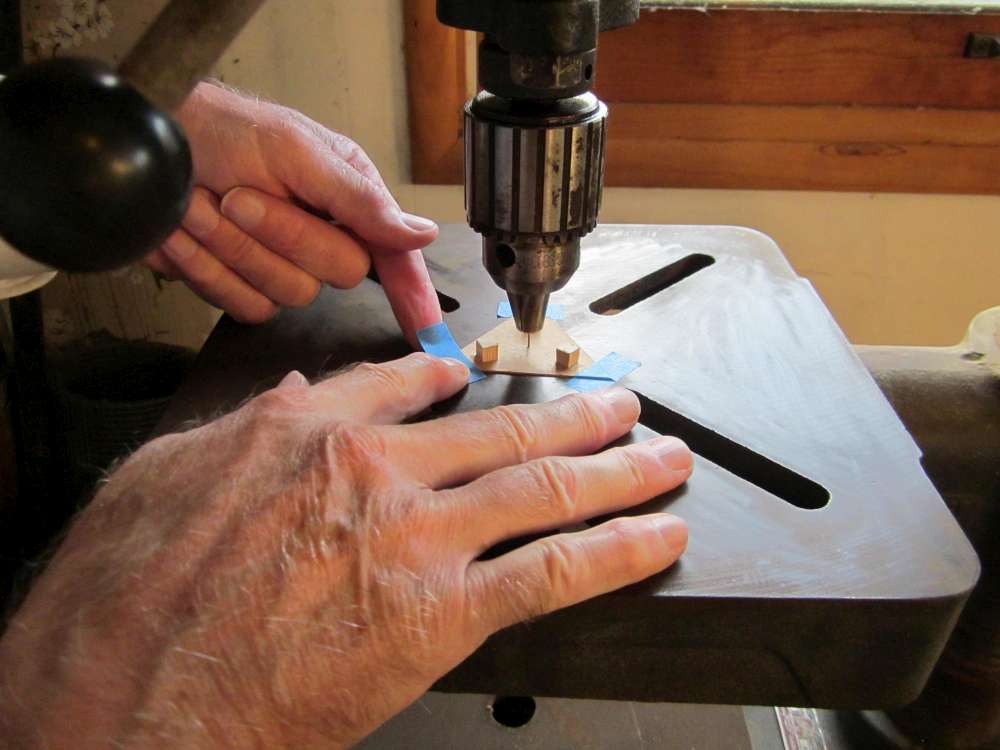
Tape the corners of the jig to the drill press table.
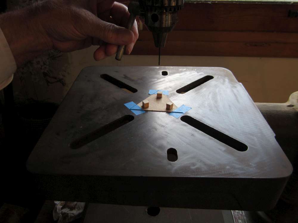
Unlock and raise the drill.
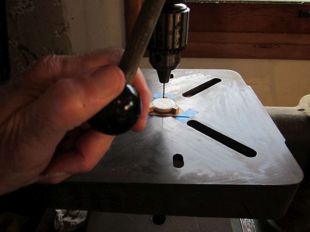
Replace the wire with a 1/16″ drill bit and place a wheel in the jig.
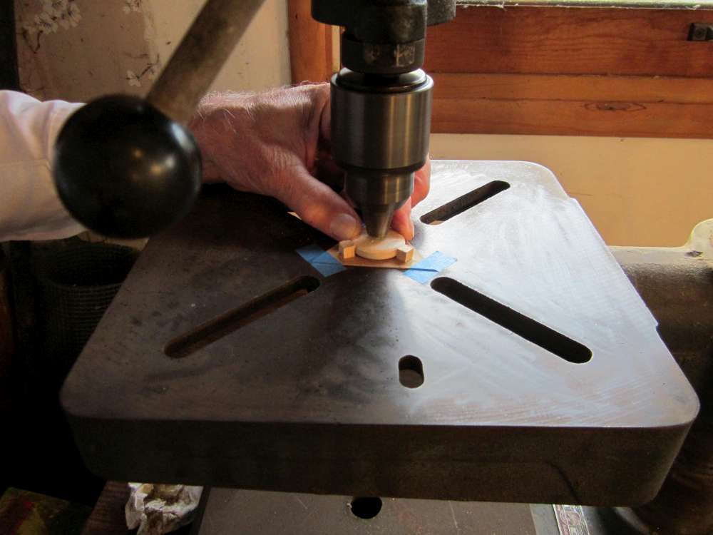
Hold the wheel and bring the drill down to bore the hub hole. Repeat for the other wheel. (Next time you set up the jig you can use the 1/16″ drill to center it.)

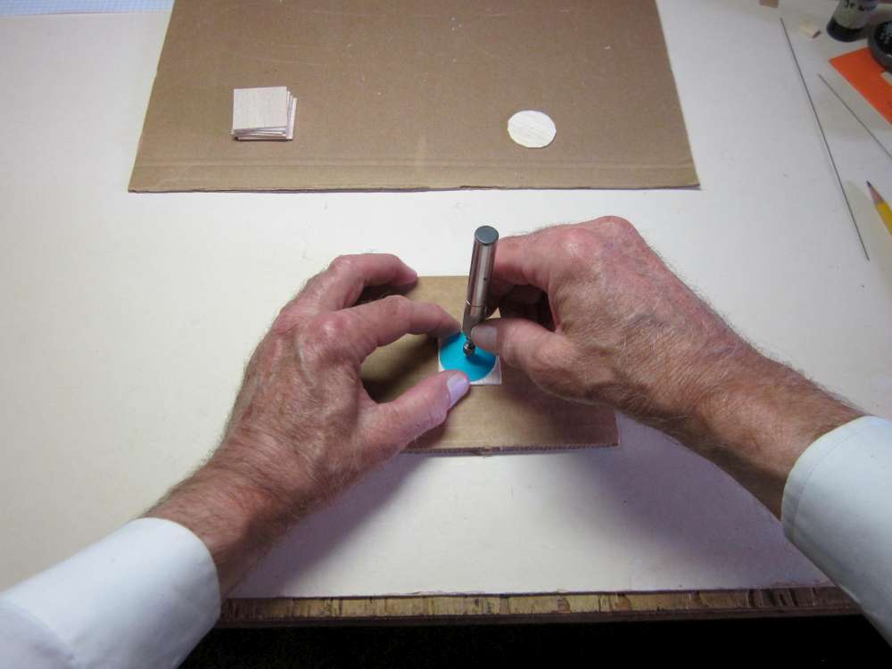
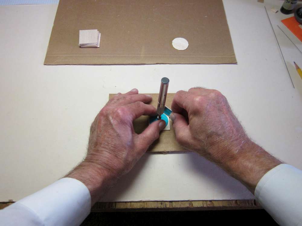
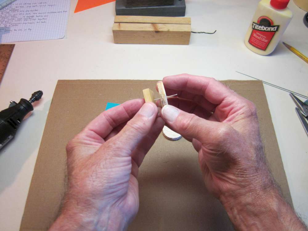
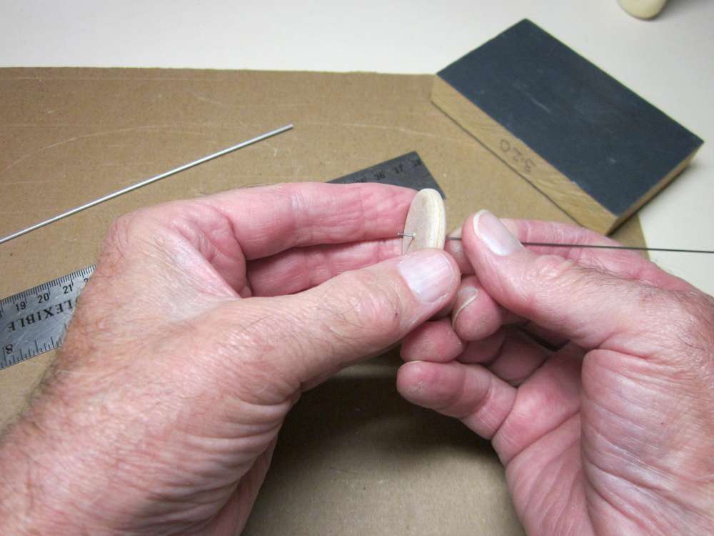
If you do not have access to a drill press, you can use a drill guide to accomplish the task. Start by widening the 1/32″ hole a little to give the drill bit something to center in.
Put the drill through the drill guide and center the tip in the starter hole.
Hold the drill guide flat to the face of the wheel and turn the drill between your fingers to drill the hole.
Sand the end of a piece of 1/16″ aluminum tube.
The tube will stick out 1/32″ from each face of the wheel.
Sand the freshly cut end of the tube.
Remove any burr on the ends of the tube.
Push the pointed end of a round toothpick into one end of the hub.
Cut the toothpick off at the face of the hub. This toothpick will keep glue out of the tube. Sometimes I roll the hub under a file to roughen the surface.
Smear glue all over the hub.
Twist the hub into the hole in the wheel. (It might be useful to try a dry run to make sure it will go in easily.)
Let the glue dry thoroughly, then push the toothpick out of the hub with a piece of 1/32″ steel wire.
WING SADDLE
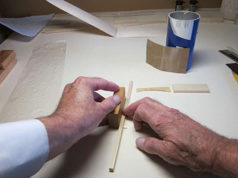
Place the straight edge of the side plate against a block and press a length of 1/4″ square against the block.
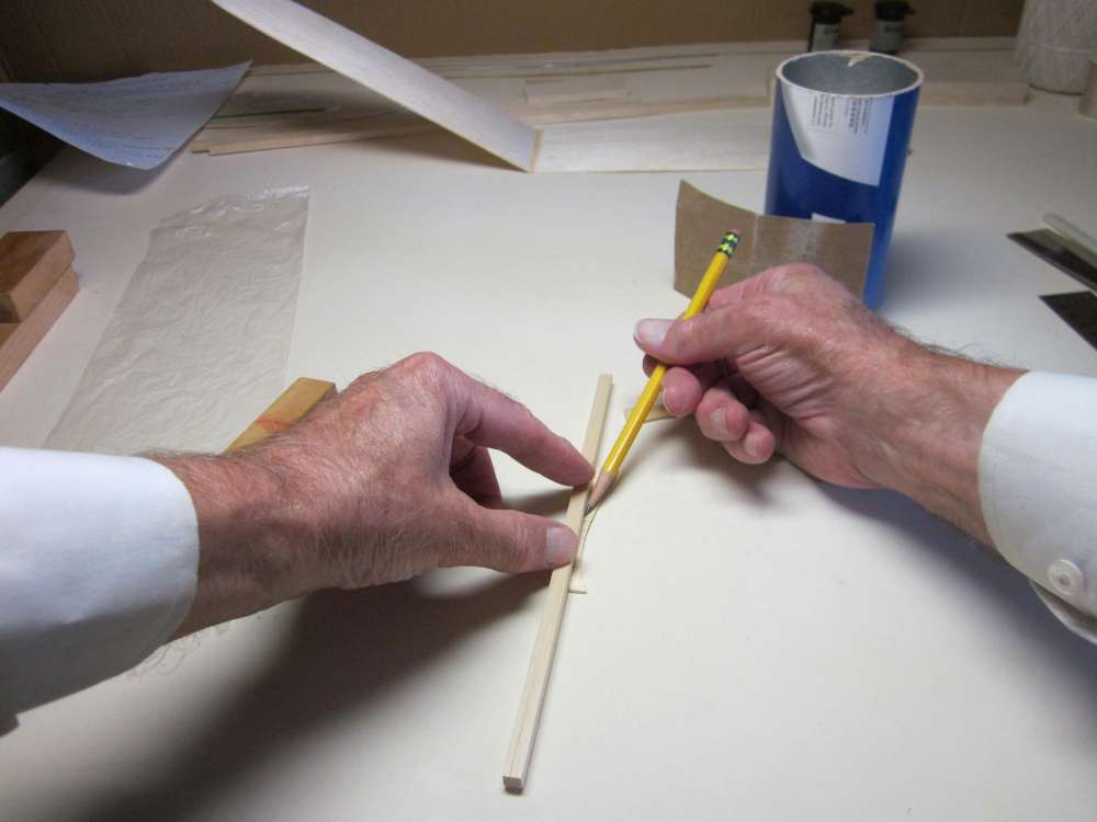
Draw a pencil line right along the face of the 1/4″ square.
Do the same with the other side plate, but note that this is the mirror image of the first. They are not the same; one is left and the other is right. It should be possible to put them exactly face to face with the pencil lines matching on the inside.
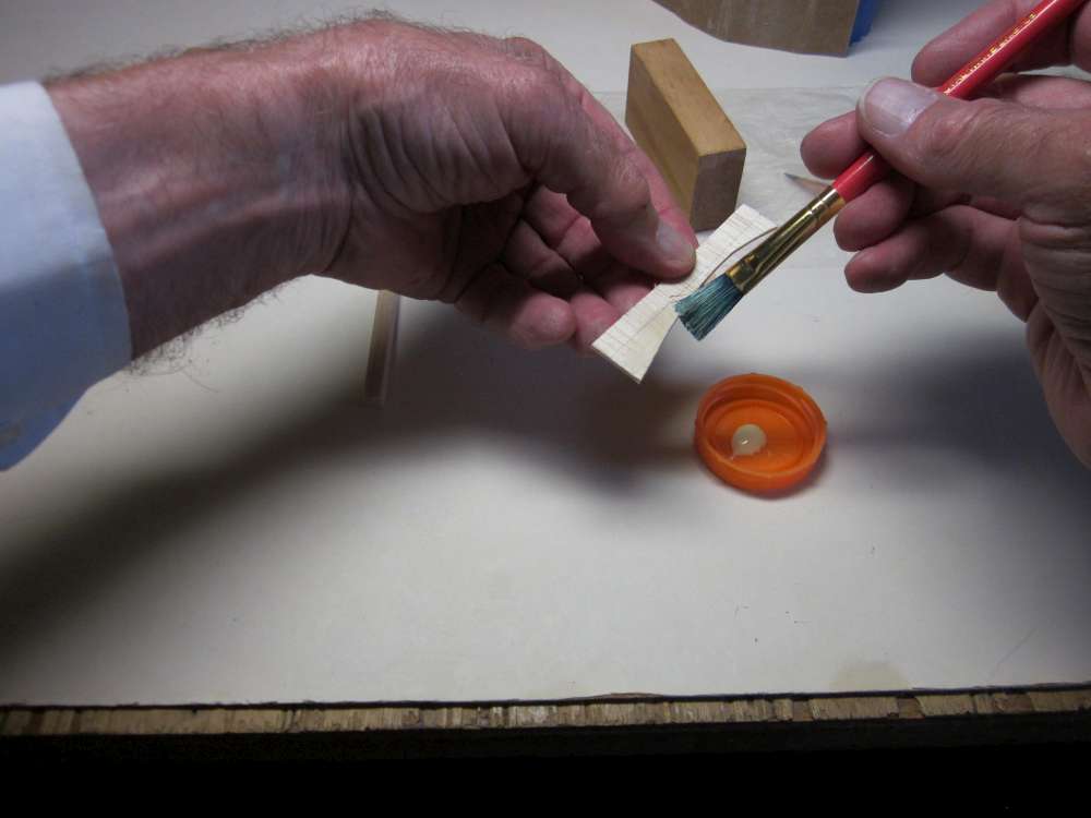
Paint glue on the portion between the pencil line and the curved edge.
You will have cut a block of 1/8″ sheet 2 15/16″ long and at least 3/4″ wide. This piece came out of my scrap box. Place the edge of this block exactly along the pencil line and press the pieces together.
Do the same with the opposite side plate.

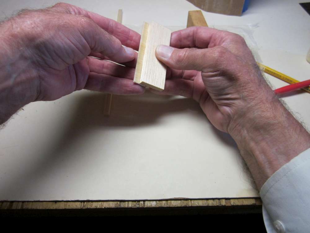
Place a piece of 1/4″ square on the table, cover it with a piece of thin plastic film (vegetable bag), press the two side plate straight edges down to the table top and press the central block down to the 1/4″ square. Check that the front and back edges of the two side plates align with each other.
With a block on either side, firmly press the assembly together and hold until the glue gels. Set this aside to allow the glue to dry.
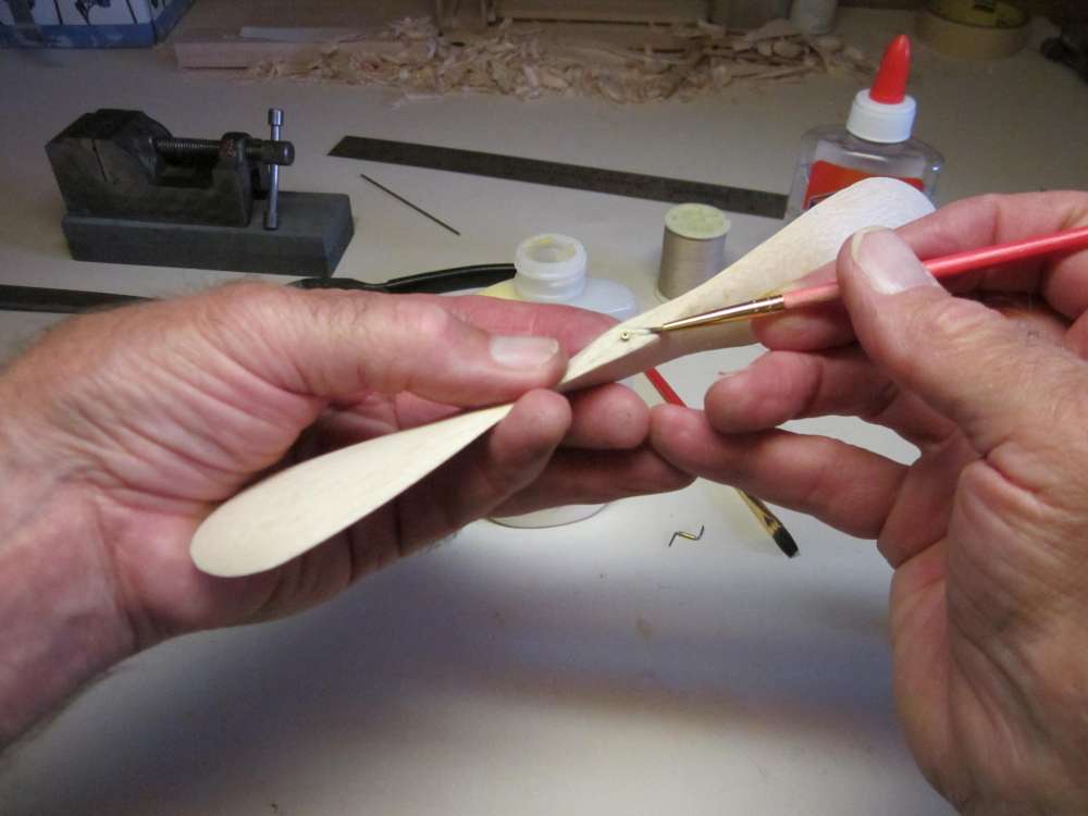
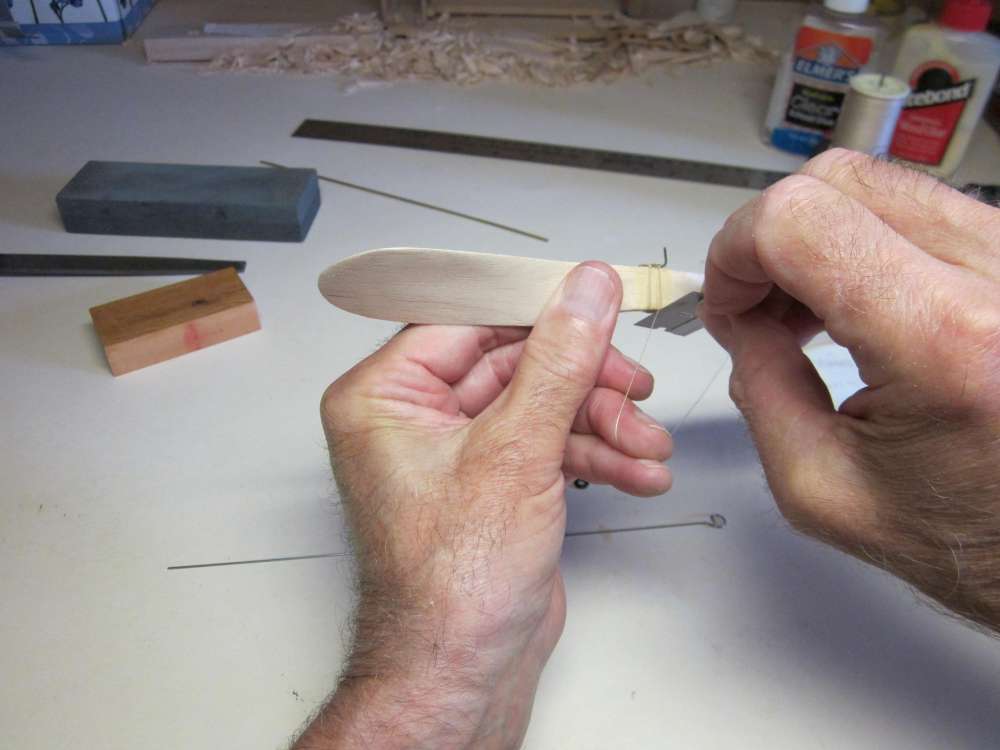
After the glue has dried, with the stick kept inside the side plates to support them, cut away the excess block about 3/32″out from the curve.
Sheathe the knife when done to prevent injury.
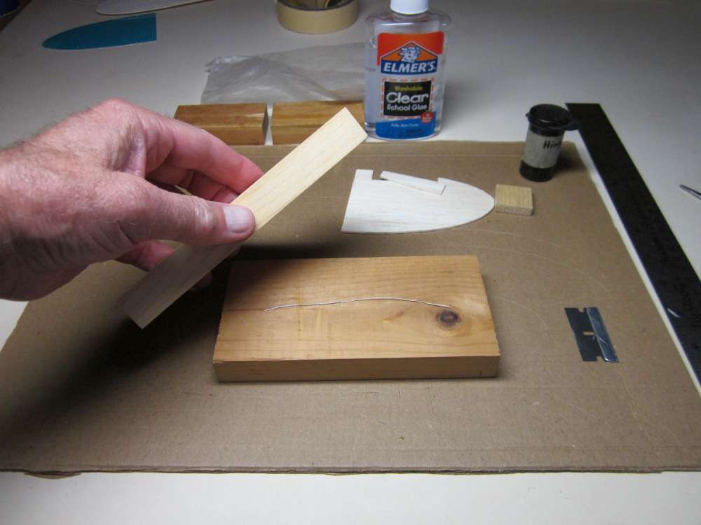
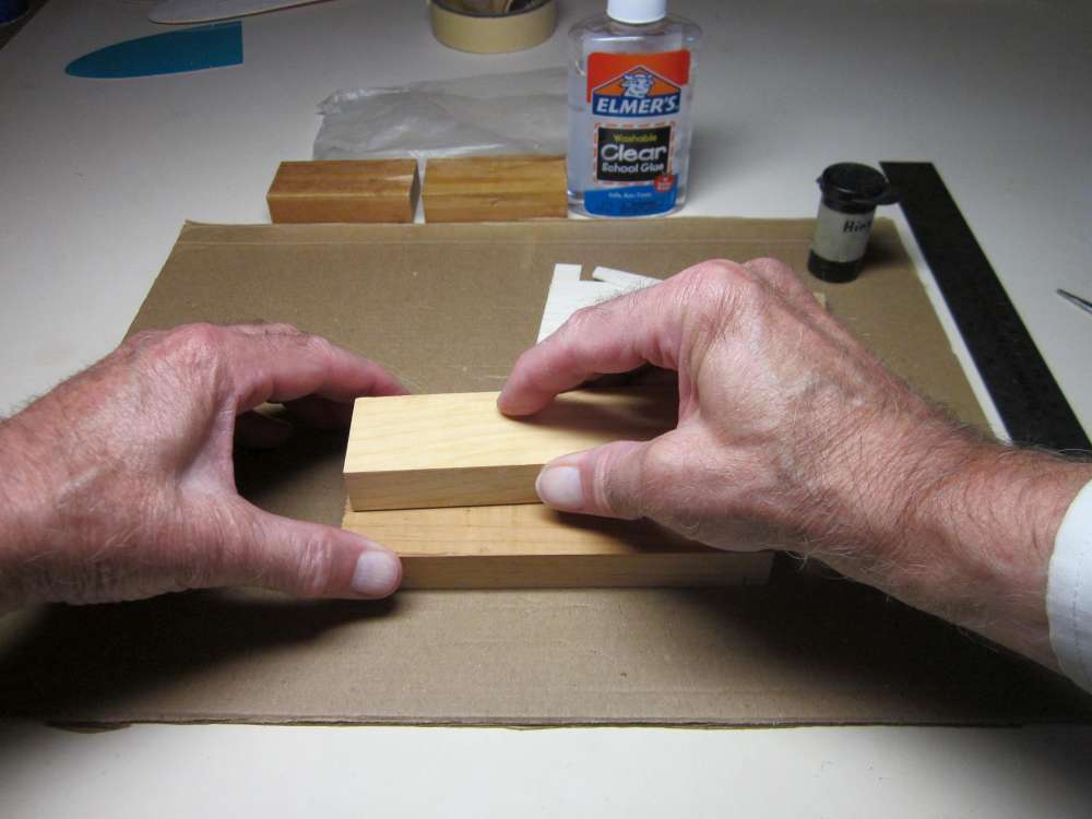
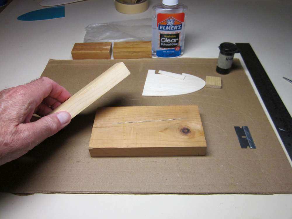
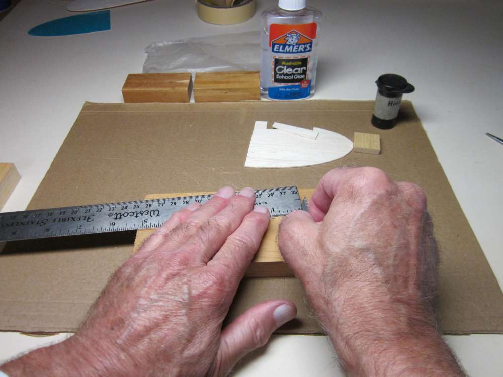
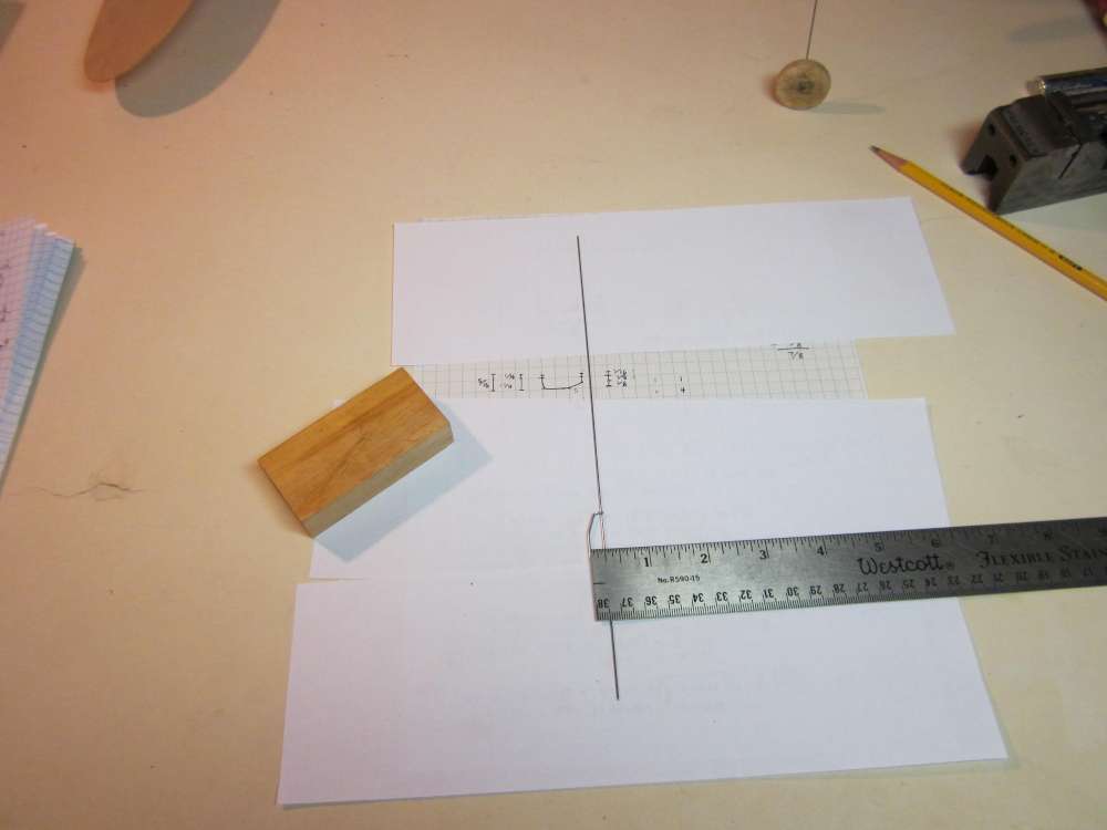
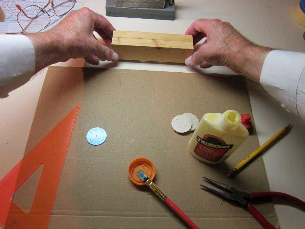
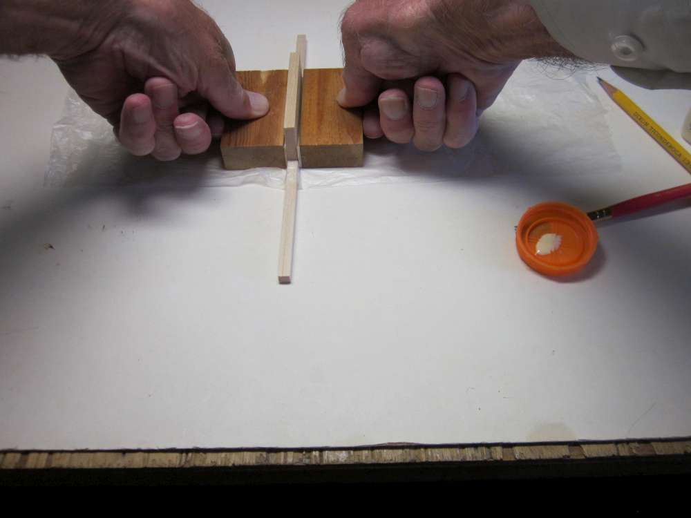
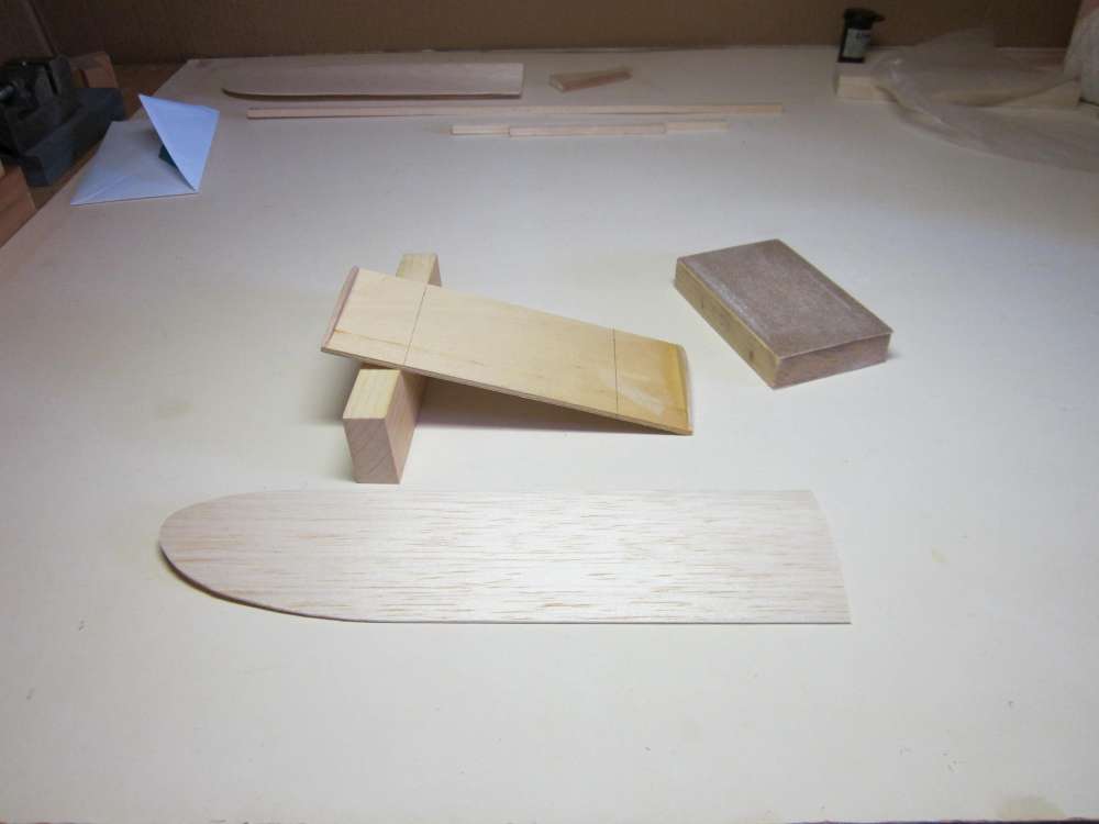
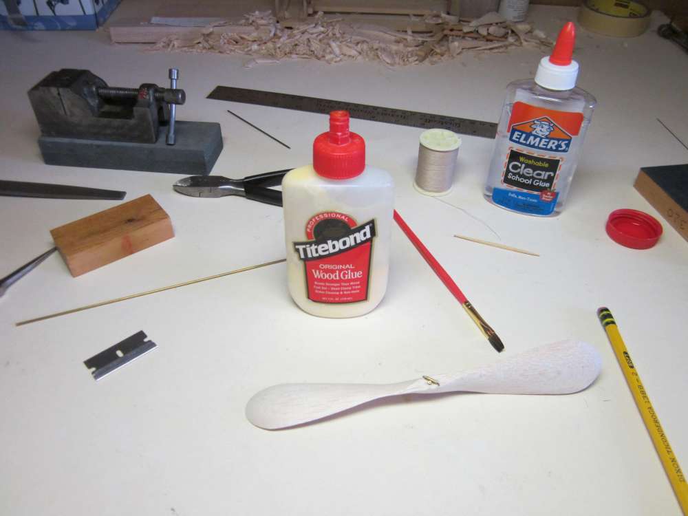
To sand the correct dihedral bevel into the wing saddle we must place it on an angled board while we sand it. Start by marking off a 5 1/2″ length on the board. Mark on both sides of the board. This board will be placed on a slant with the marks on the edges of a 1 1/2″ block to form the dihedral angle.
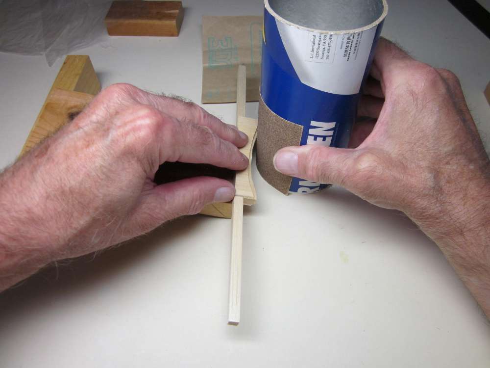
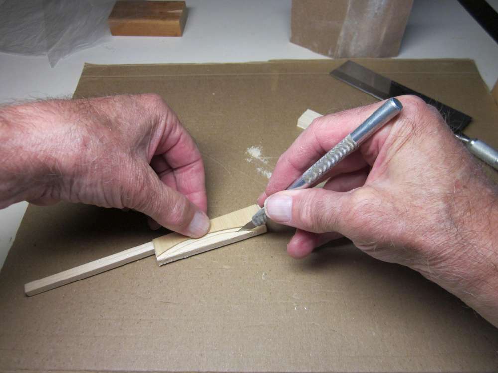
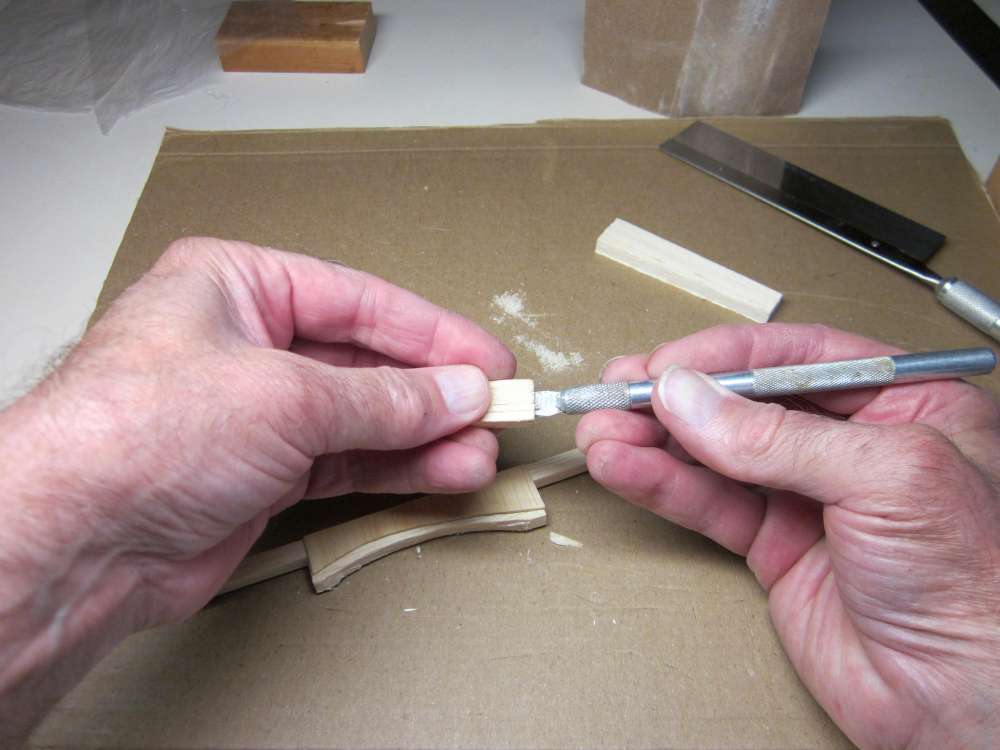
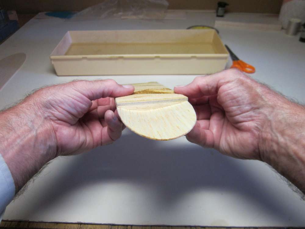
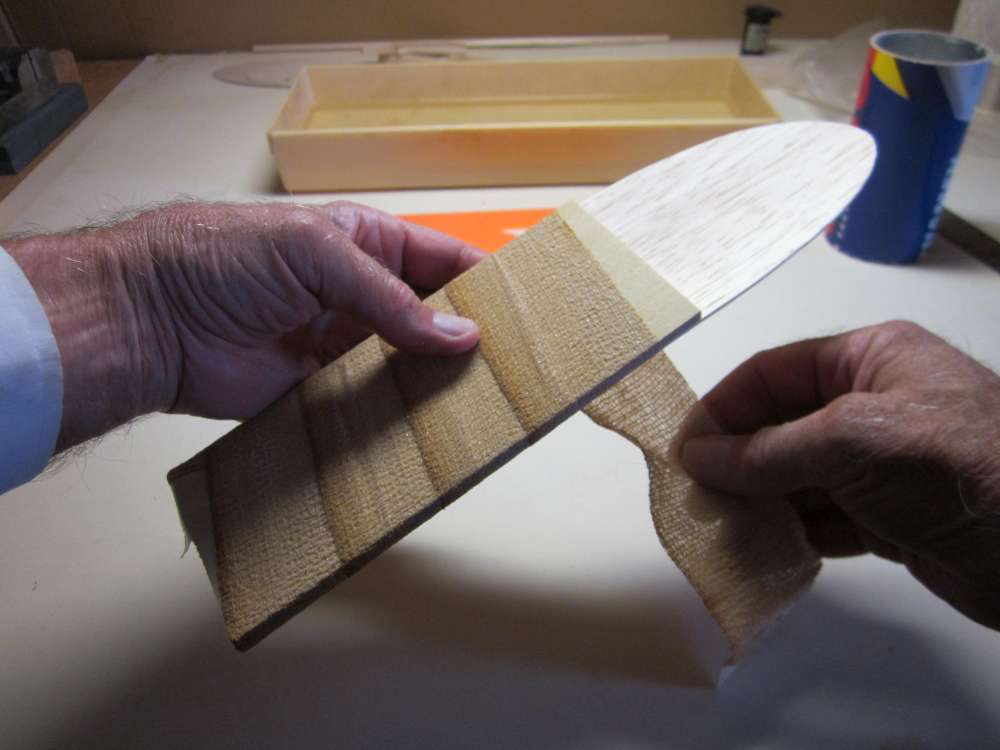
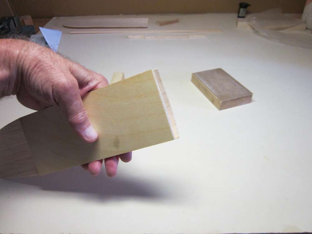
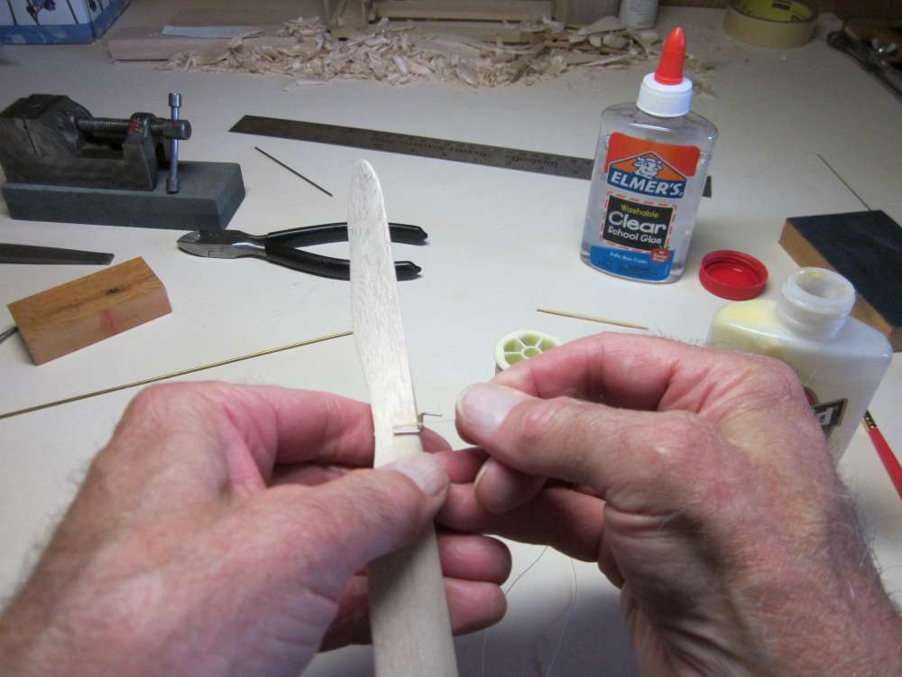
Hold the wing saddle firmly straight across the bottom edge of the slanted board and sand the bevel into the central block. Wrap some 100 grit sandpaper around a sturdy cardboard tube. It is easier if the paper is taped to the tube. The radius of the tube should fit inside the curve along its entire length, in particular the tightest curve near the front of the airfoil. The tube seen here is 2 5/8″ in diameter and originally contained badminton birdies. Sand down just to the outside edge of the curve.
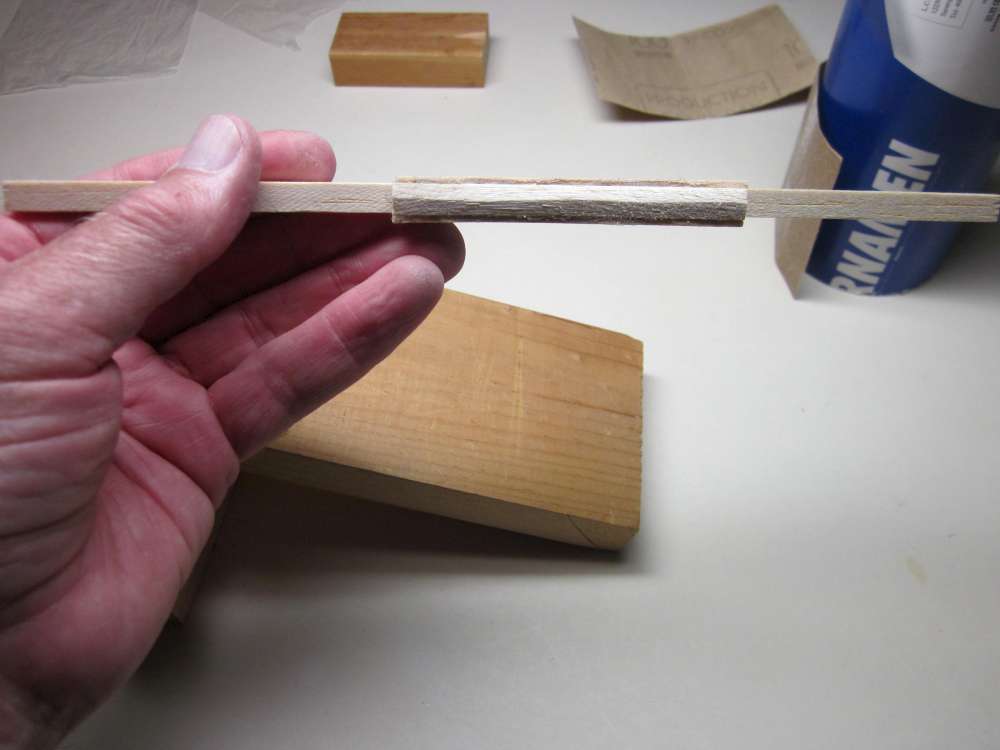
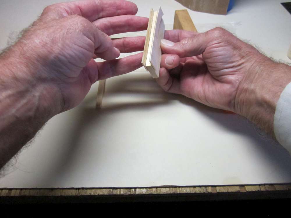
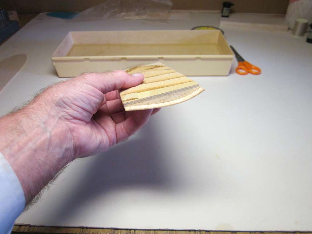
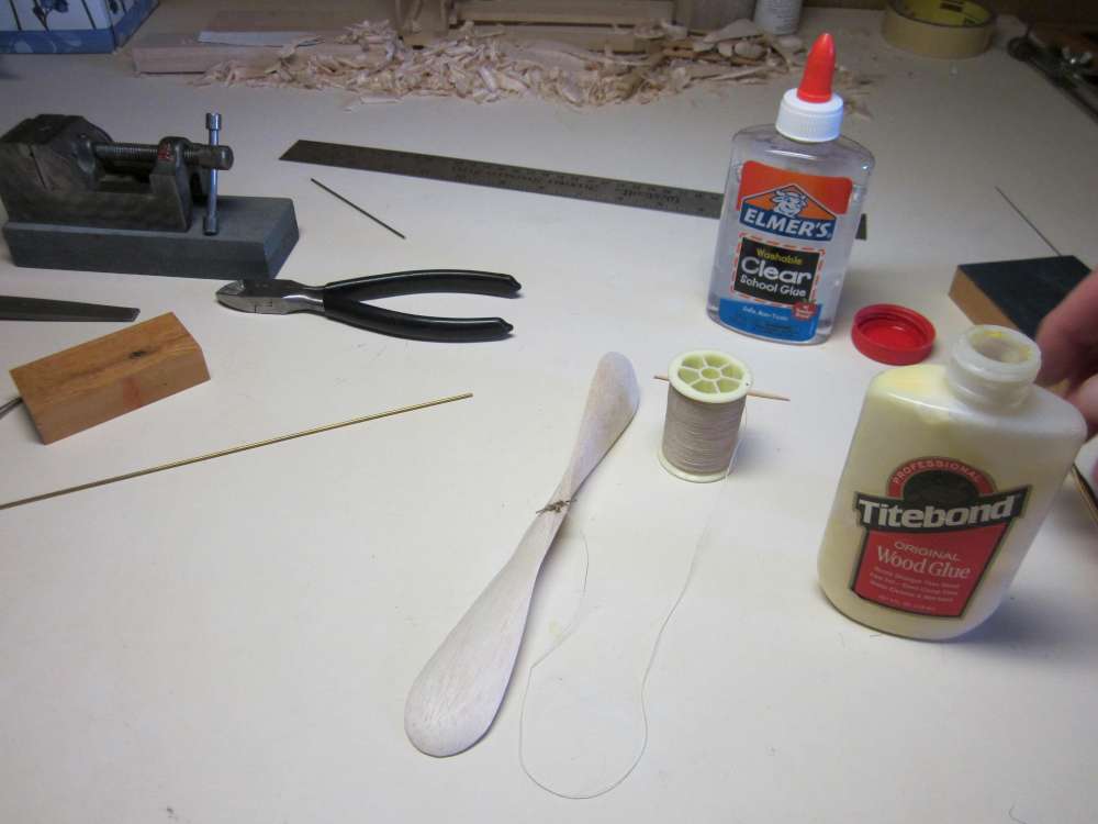
The dividing line should be exactly centered. This needs a little more work with fine sandpaper.
WINGS

The wing camber will be wet formed on a form board. The base is 1/8″ plywood, 2 15/16″ wide and 7″long. Across each end is glued a rib of the same pattern as we drew for the side plate. Pencil lines are drawn across 5 1/2″ from each end to locate the 1 1/2″ blocks that will tip the board up for the dihedral angle.
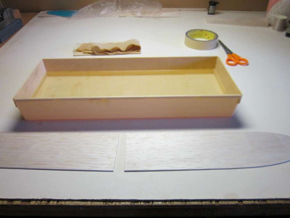
The wings are wet formed by putting them in a tank of water. On my first Cloud Tramp I completely submerged the wing in the water and let it soak. The wood swells and doesn’t quite fit on the form. This time I tried something different.
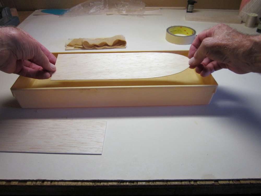
I dropped the wing onto the surface of the water with the top surface down just long enough to wet it. This causes the top surface to swell, facilitating the desired curvature without excess swelling. It occurs to me now that the wing could have been wet with a wide brush or wet cloth.
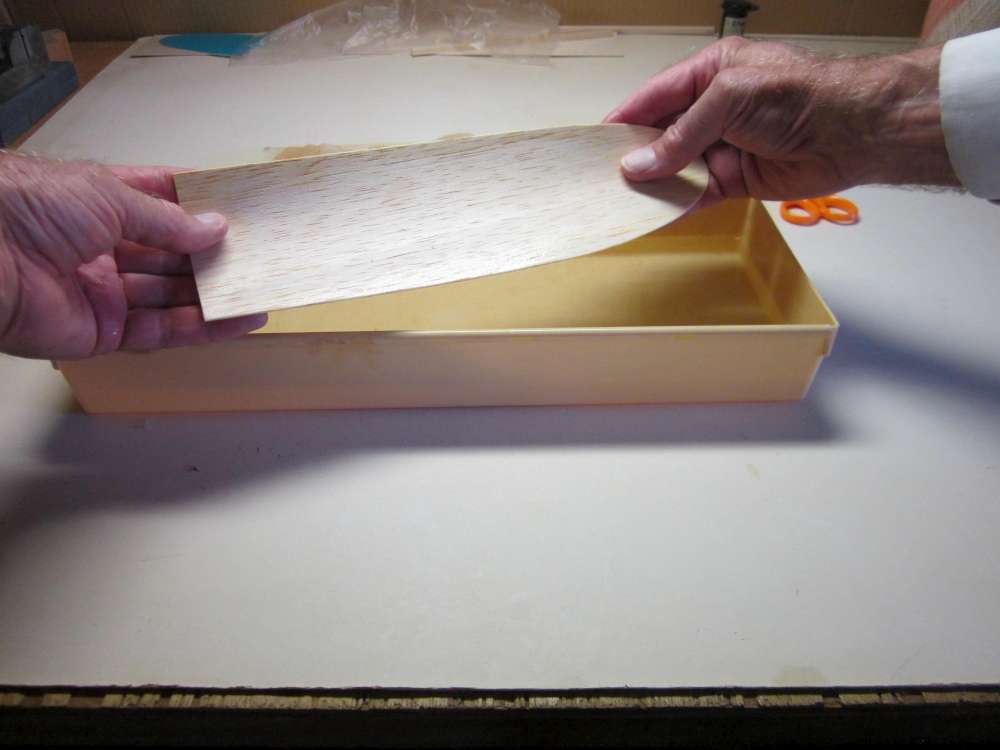
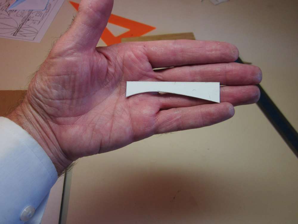
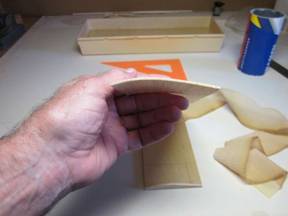
When removed from the water, the wing will have an arc.
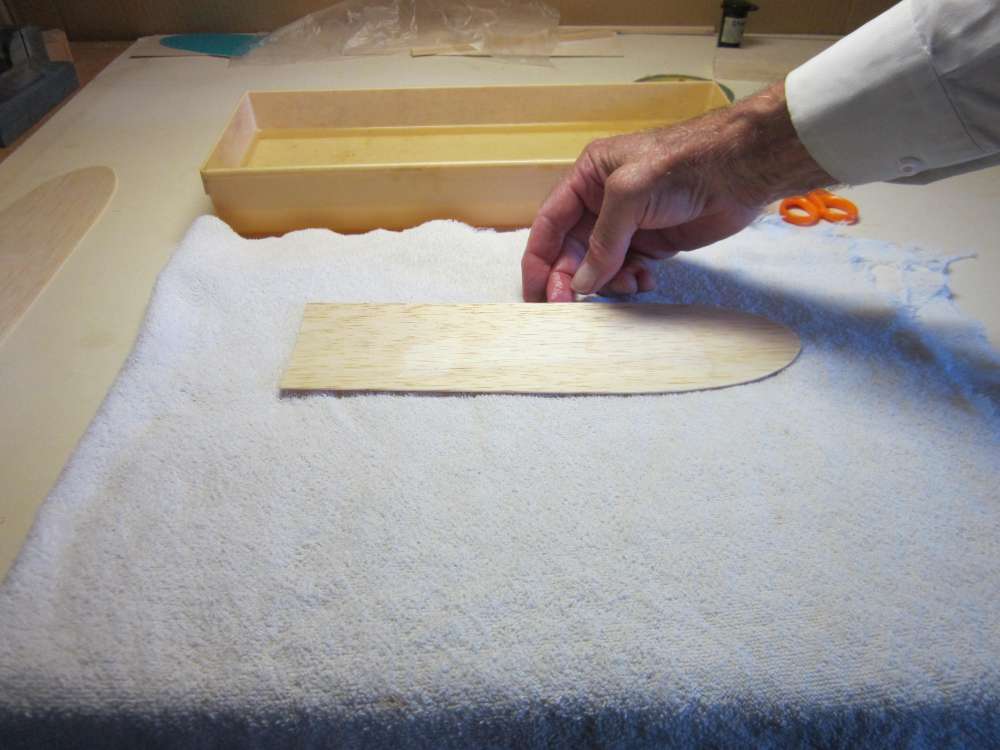
Place the wing on an absorbent towel.
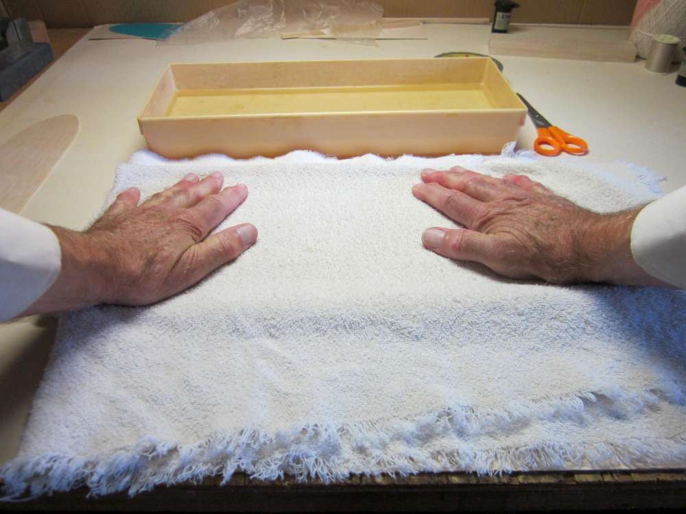
Fold the towel over the wing and press down to remove excess water.
Put the wing on the form with the wet side up.
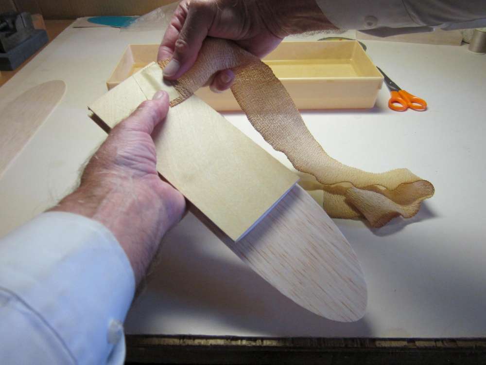
Start by taping a 26″ length of 2″ Ace bandage to the back of the form at the root end, leading off the trailing edge.
Align the trailing edge of the wing with the trailing edge of the form.
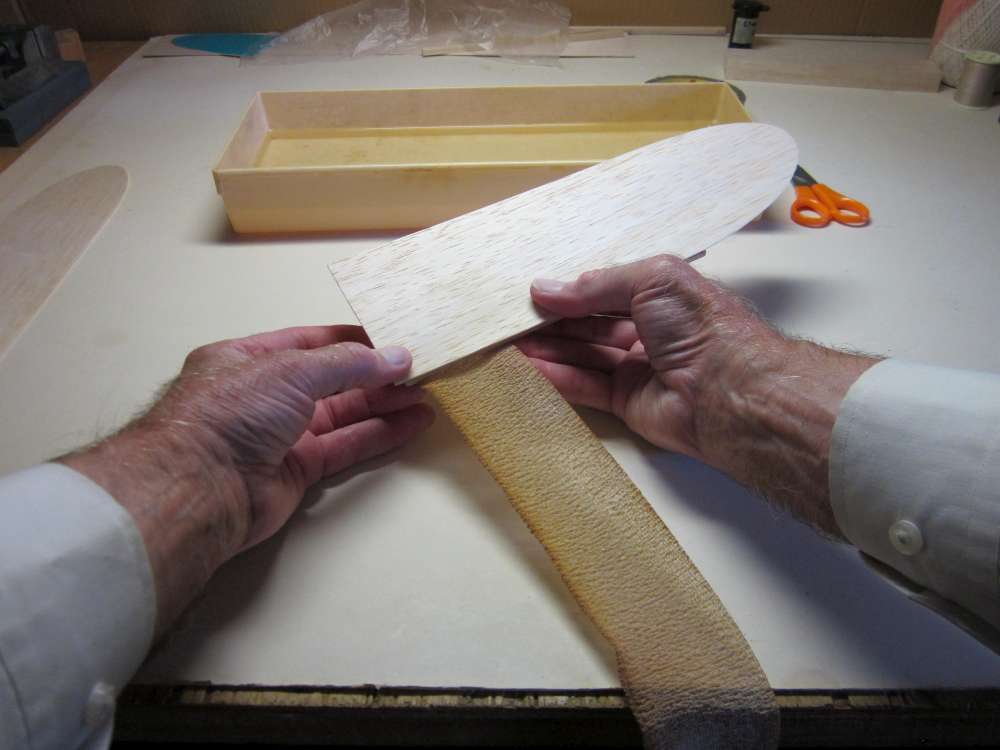
Wrap the Ace bandage around the wing and the form to hold the wing snugly to the form.
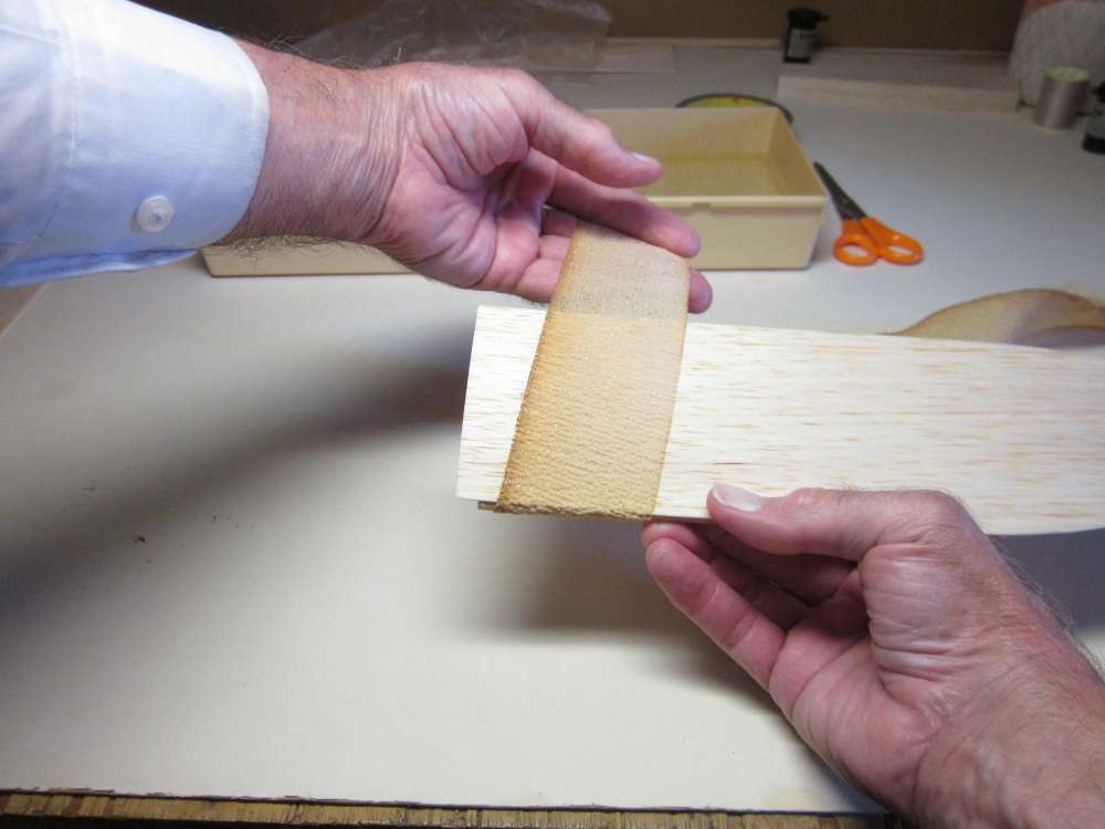
Wrap the Ace bandage the whole length of the form and tape the end in place.
Check that the edges of the wing align with the edges of the form.
Check on both ends. If everything is satisfactory, set the wing aside to dry.
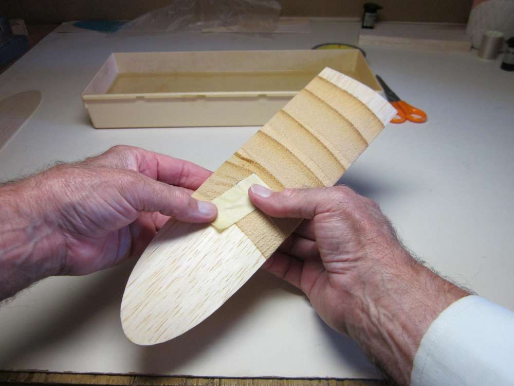
When the wing is dry, the Ace bandage may be removed.
The balsa sheet now has the proper cambered airfoil.
When that wing is done, do the same with the second wing. Remember that there is a left and a right wing, they are not the same. Double check the alignment before you strap it to the form. Butt the two wings together and make sure you have a right and a left.

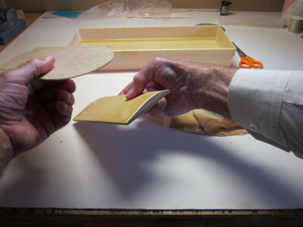
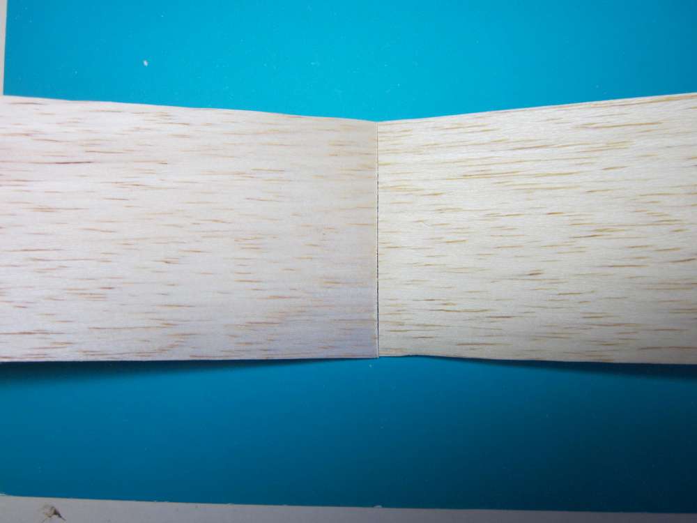
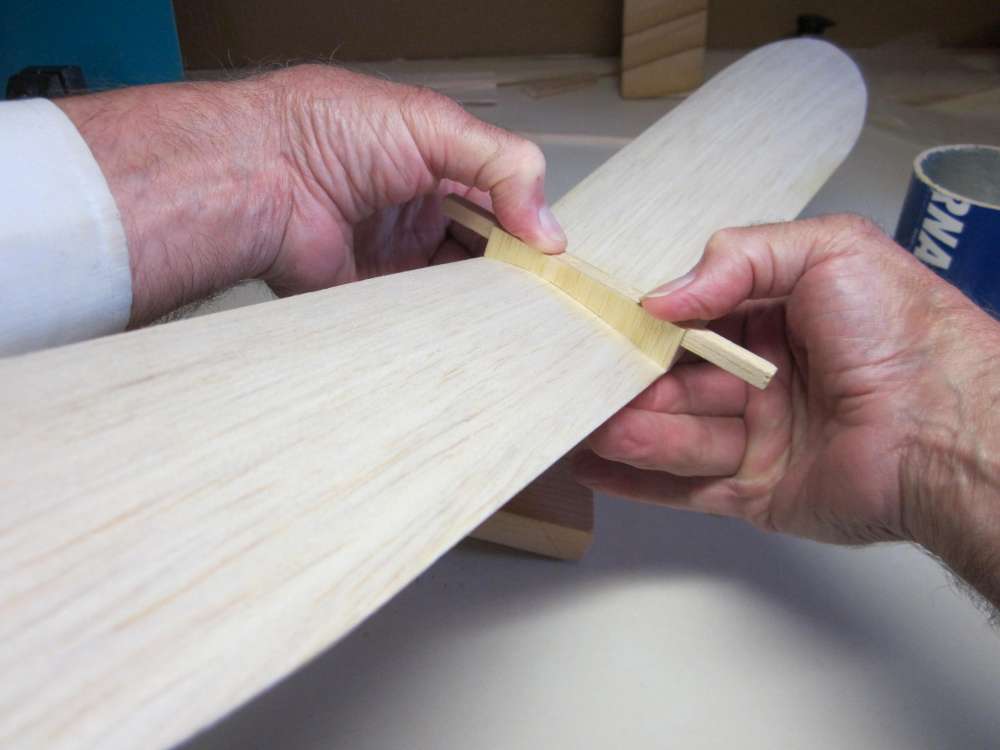
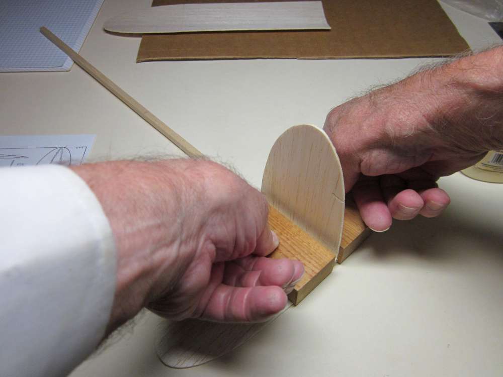
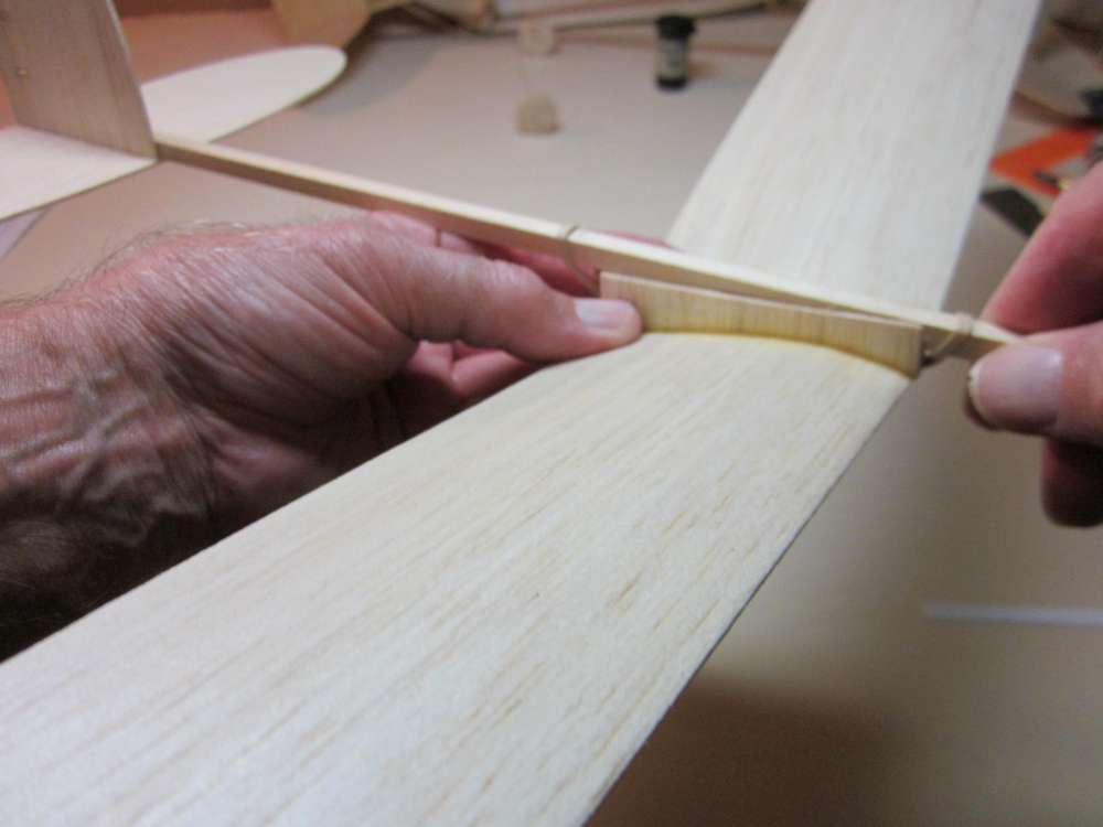
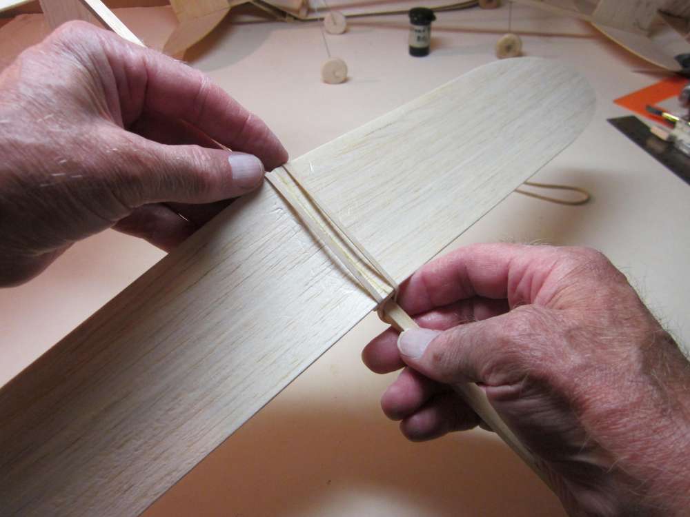
When the wings are dry, we can prop them up with the required dihedral angle to see how they fit together.
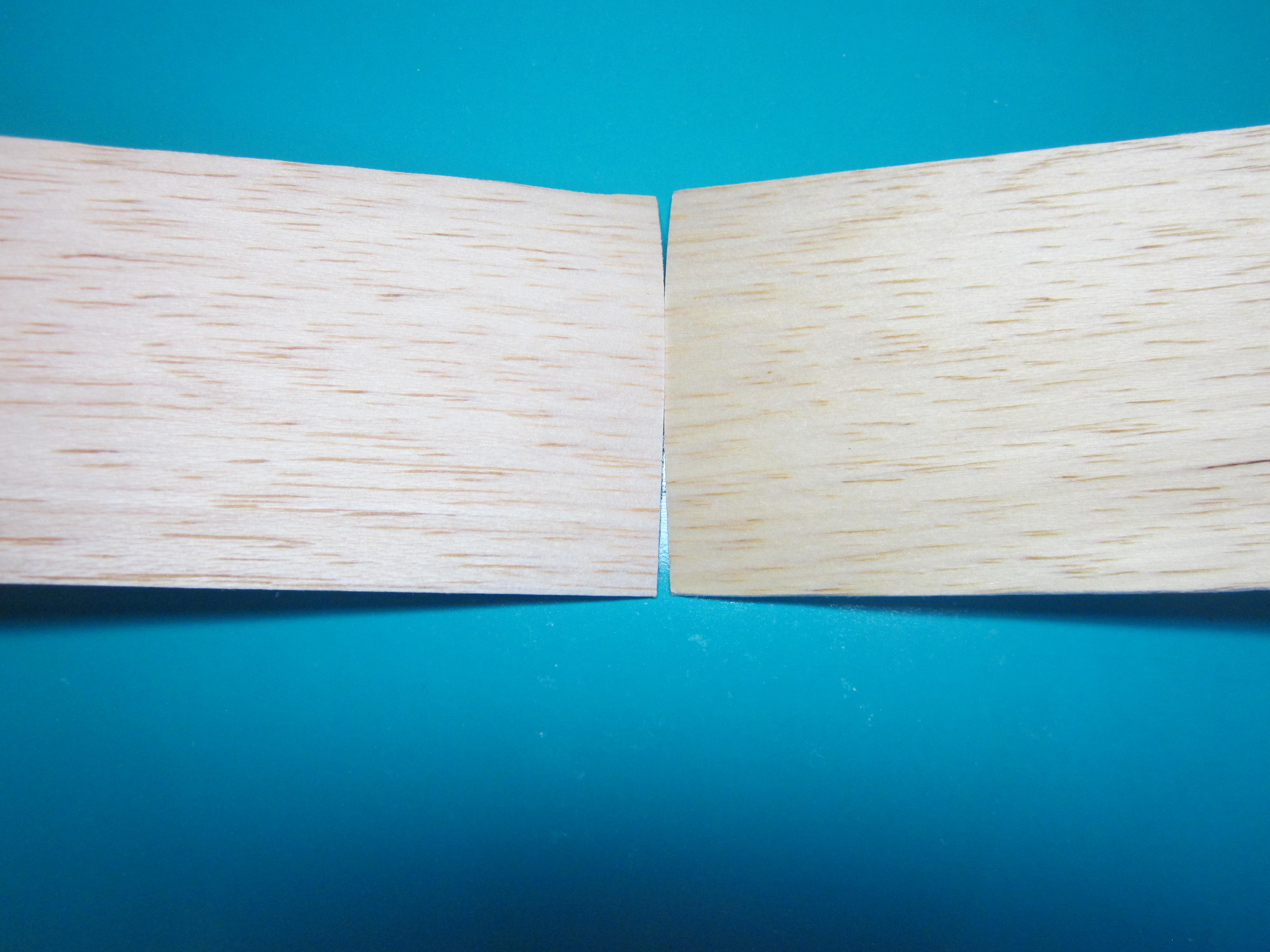
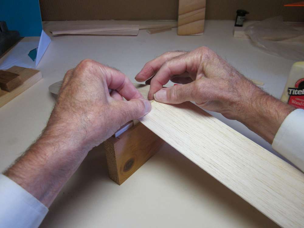
We find that when the tips are raised, the high points of camber come into contact, but there is a gap between the leading and trailing edges. We must sand a dihedral gore in the root of each wing.
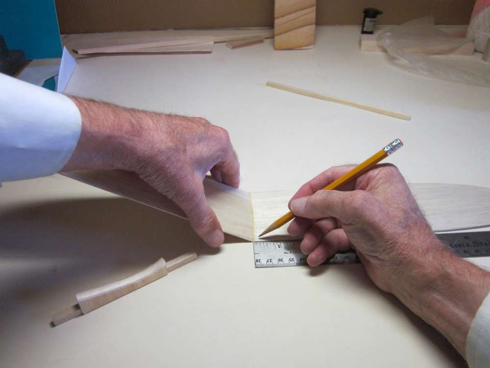
Place a 1 1/2″ block under the pencil mark on the form board. Orient the form board to match the wing you are sanding, in this case the leading edges of both are away from me.
Hold the wing to the board with about 1/4″ overlapping the end. (I did this by hand. It might be easier to use the Ace bandage or gaffer’s tape.)
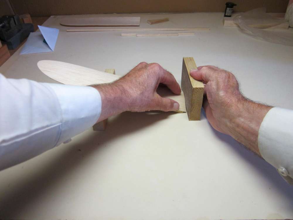
With the edge of the sanding block held flat to the table, so the sandpaper is perpendicular to the table, sand away the excess wood. Hold the wing root firmly to the end rib along its entire length. Sand down just to the leading and trailing edges, but do not sand away any of the leading and trailing edges. Start with coarse paper, but when you get close to the leading and trailing edges change to fine sandpaper and slow your sanding, watching very carefully to keep the paper in uniform contact all across the chord. Do the same with the other wing, but remember, one is right and one is left.
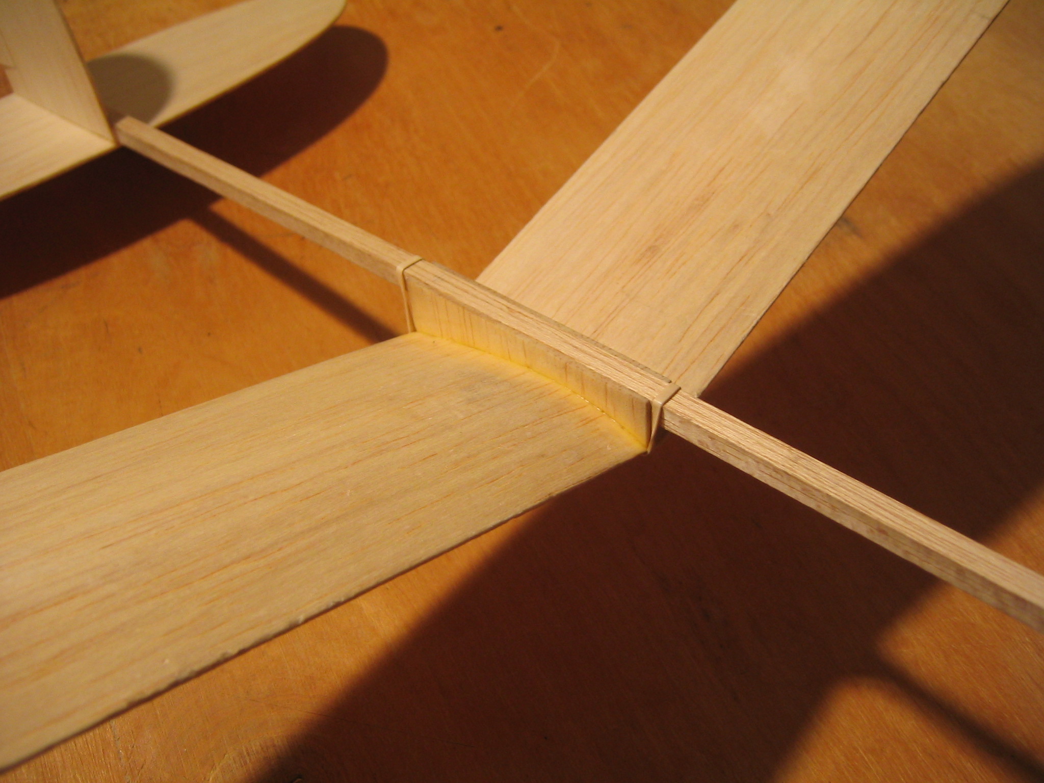
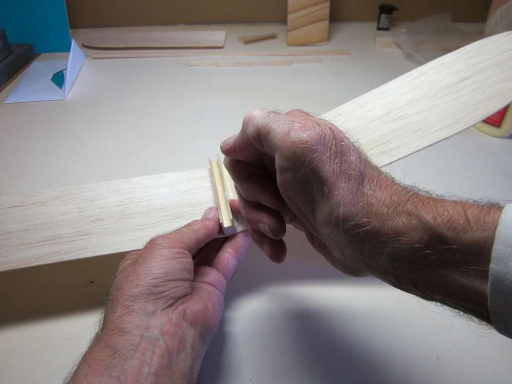
The result is a tight fit for a strong glue joint.
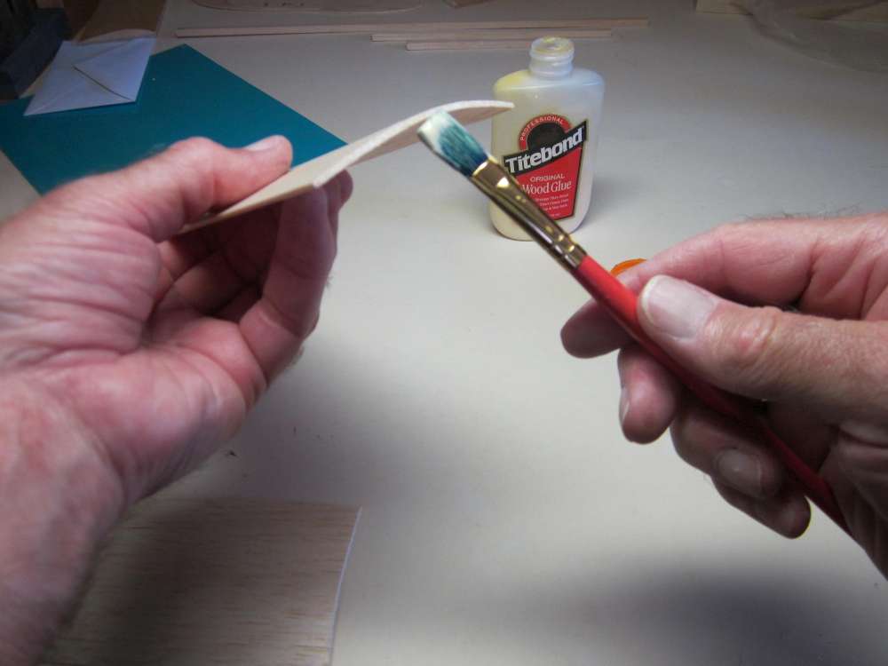
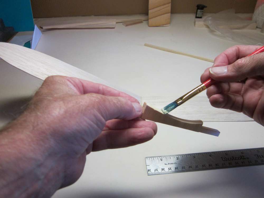
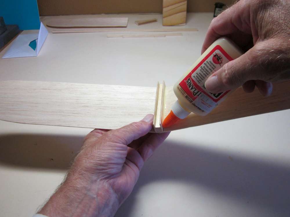
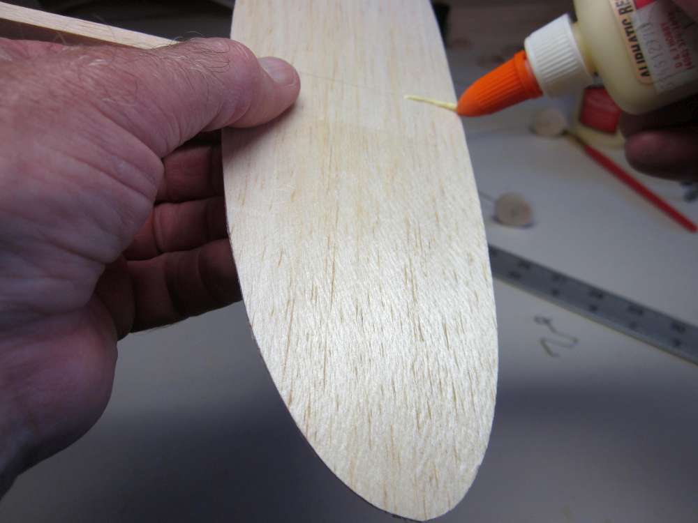
Apply a coating of glue to the ends of both wings, let it get tacky.
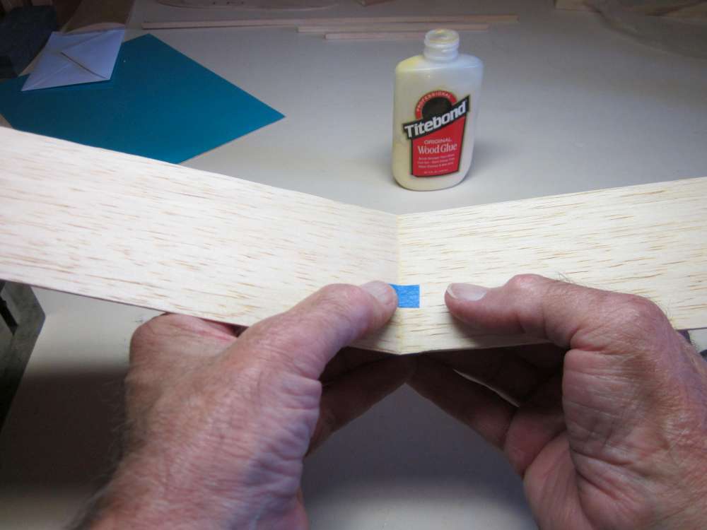
Apply a quick coat of glue to one wing root and stick them together. I find that bringing the leading and trailing edges together with a slight gap in the top and then rotating the tops together works. Make sure the leading and trailing edges align. Put a bit of tape across the top.
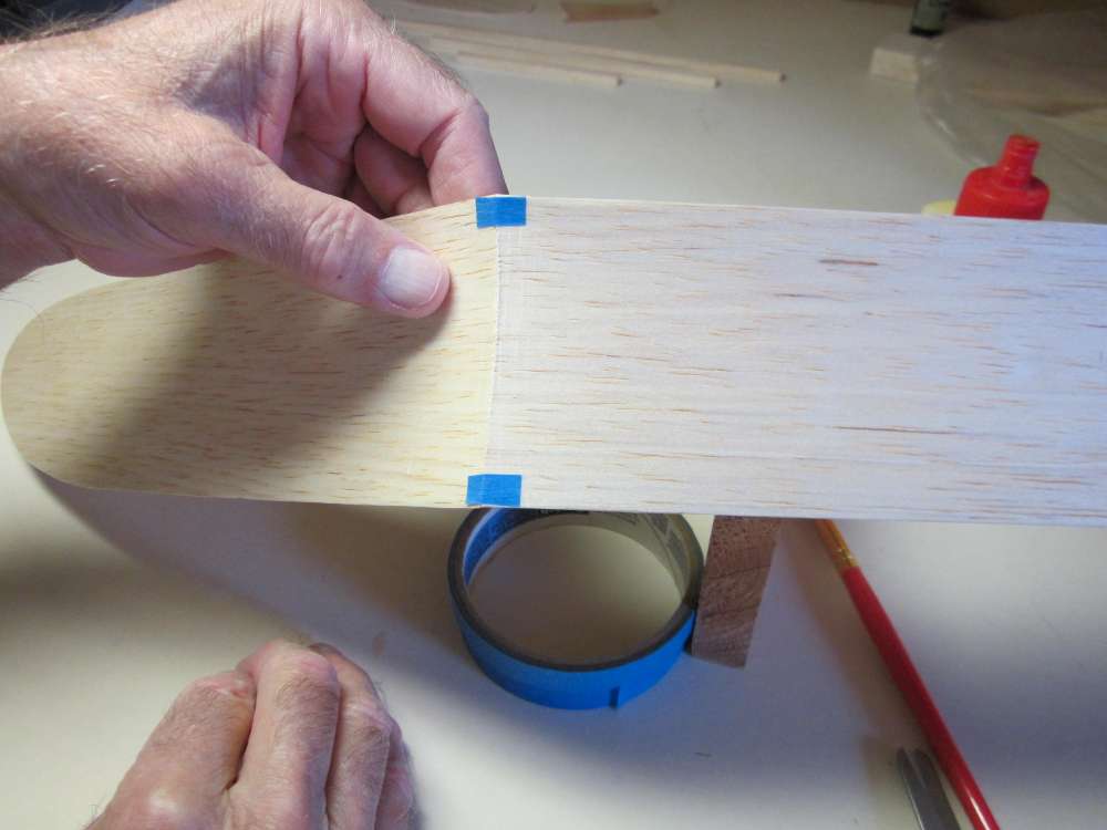
Sometimes I put a bit of tape across under the leading and trailing edges, too. Stick it first to one wing, then the other.

Set the wing down on the board with 3″ blocks holding the tips up and let the glue dry.
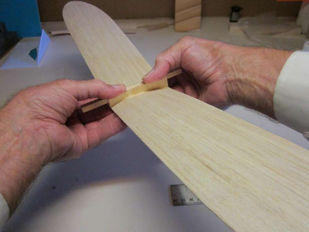
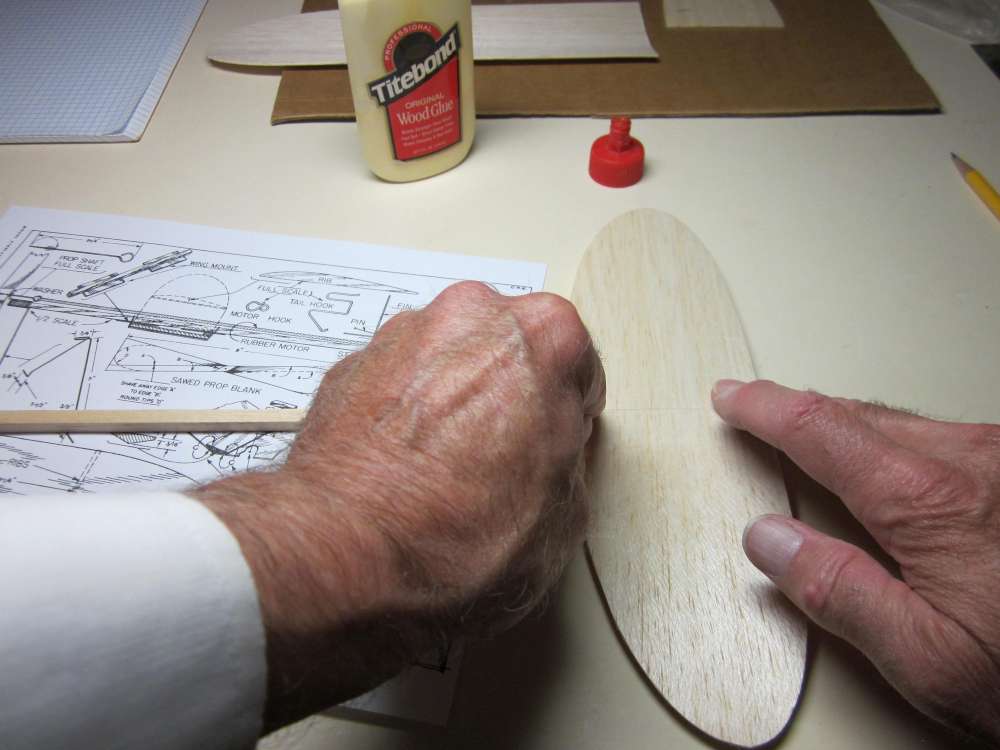
Check the fit of the wing saddle on the top of the wing.
Mark 3/16″ on each side of the center line at leading and trailing edges to locate the saddle.
Apply a uniform layer of glue to the beveled under surface of the wing saddle.
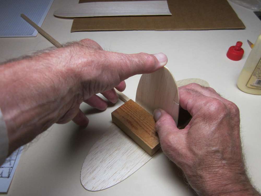
Glue the saddle to the center of the wing. Align the leading and trailing edges with the wing and center it carefully between the pencil marks.
Putting it upside down on the edge of a 3″ block of wood will allow you to judge how well centered it is. The tips will be about 1/2″ off the table, the important thing is, they should be the same. Hold it until the glue gels.
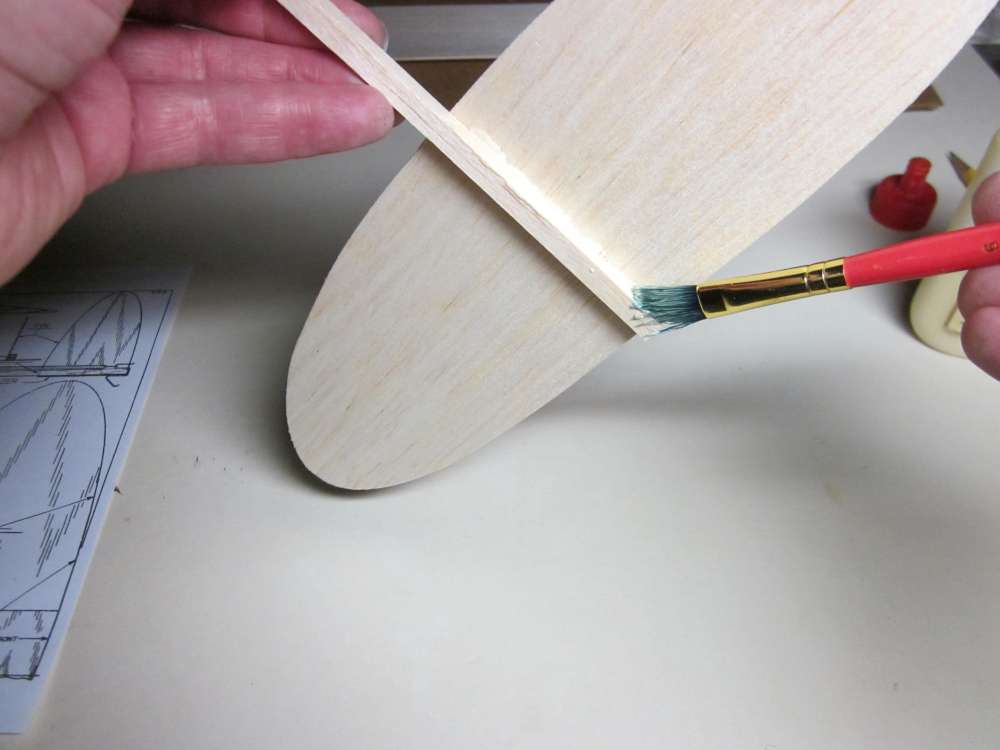
After the glue drys, run a bead of glue along the join between the wing and side plate on both sides.
Wet your fingertip and form a nice glue fillet.
TAILPLANE AND FIN
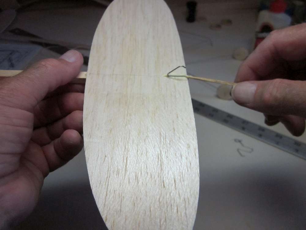
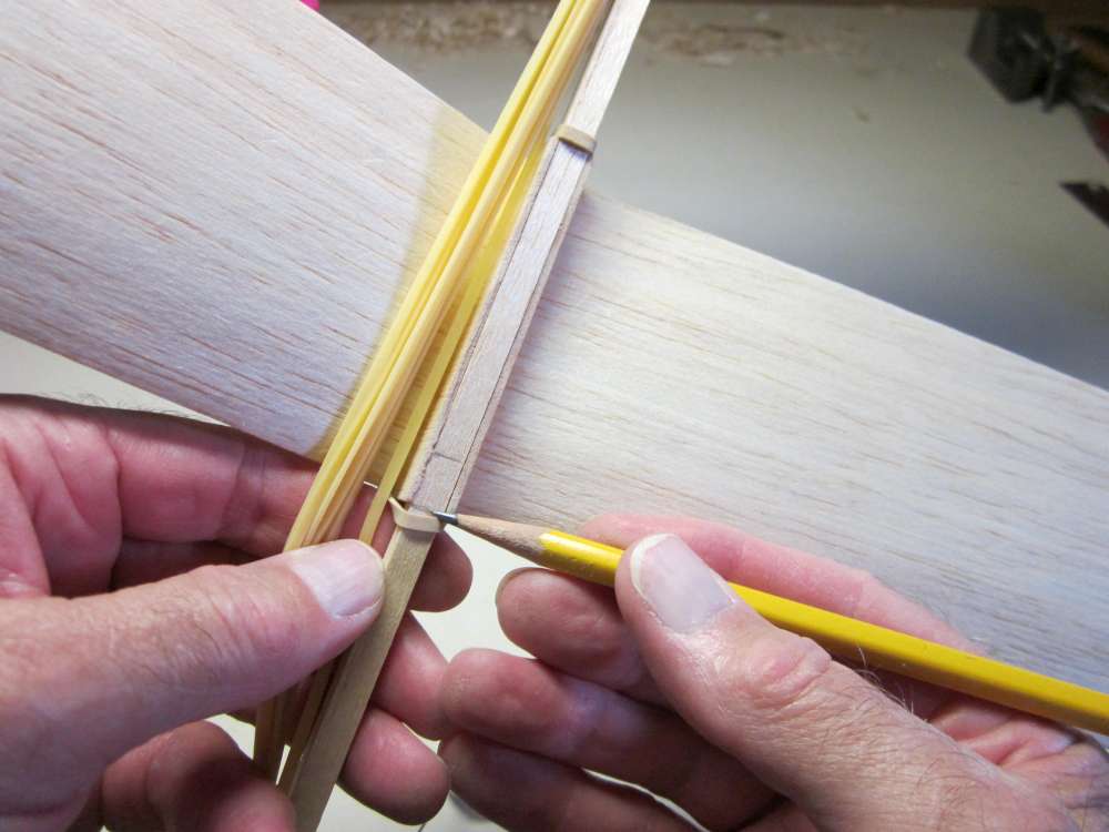
Align the trailing edge of the tailplane with the back end of the stick and mark the position of the leading edge on the stick. Remember that when we cut the stick, we balanced it and marked the heavy end as the front.
Paint glue on the marked off section of the stick.
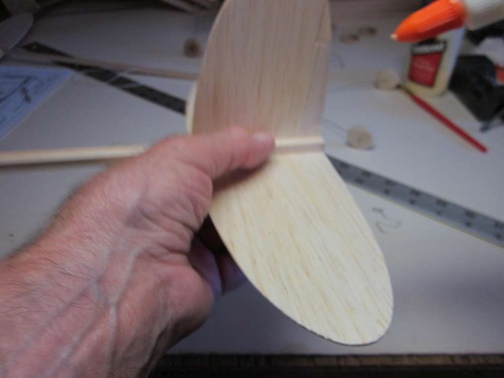
Place the tailplane on the glue coated portion of the stick, aligning the center line with the center line of the stick. The fore and aft orientation of the tailplane is shown on the plan. The tailplane has a slight sweep back.

Place a weight on the stick to hold everything together while the glue dries.
Once the glue has dried on the tailplane, paint glue on the right side of the stick.
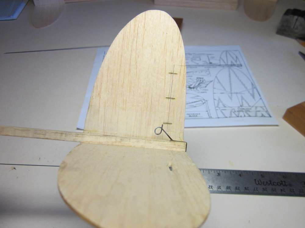
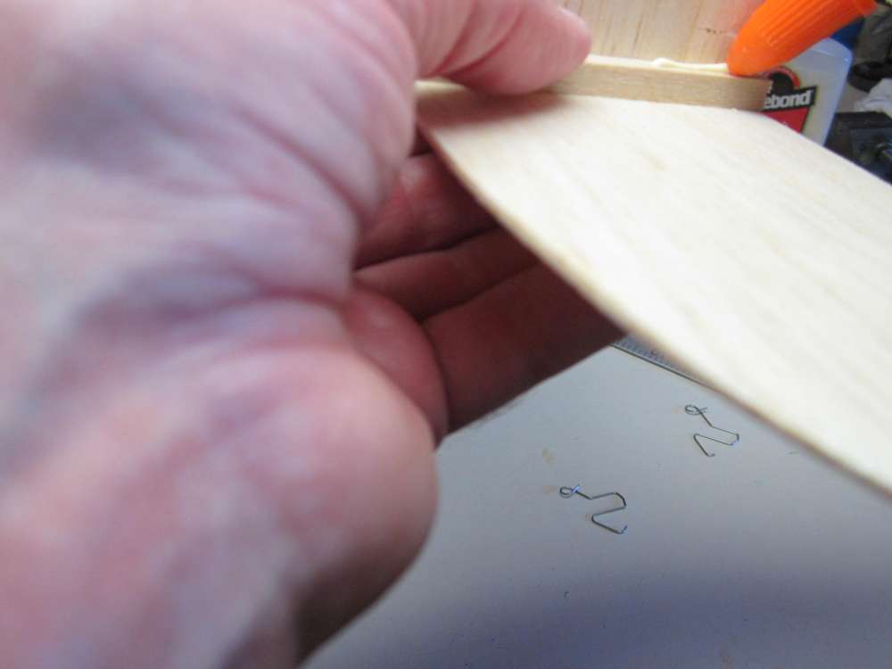
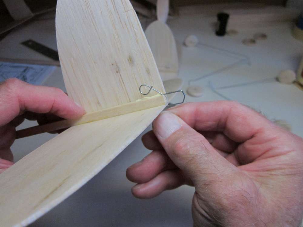
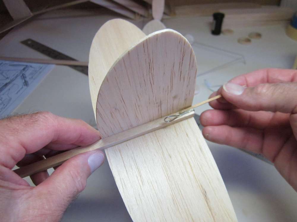
Run a bead of glue along the base of the fin and press the fin against the glue on the stick. The rudder goes to the back.
Press the fin down against the tailplane and press it against the stick with blocks from both sides. Once the glue has gelled you can make glue fillets where the fin meets the tailplane and stick.
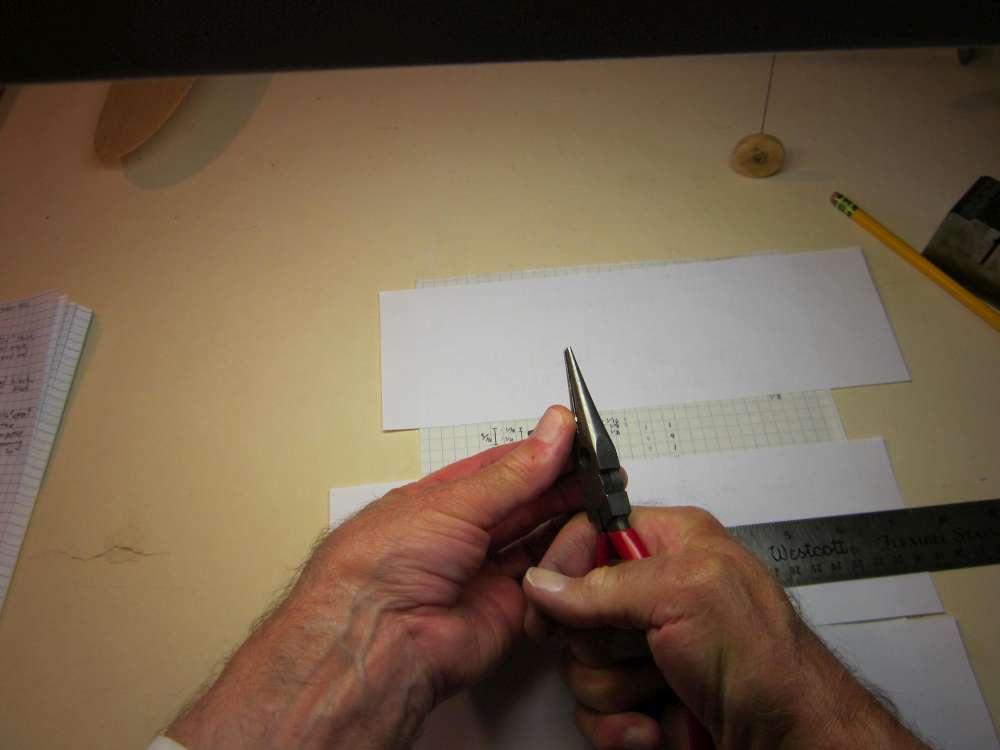
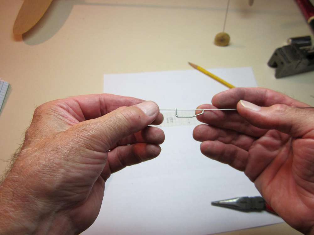
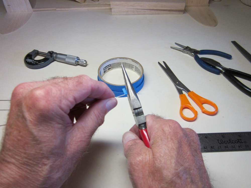
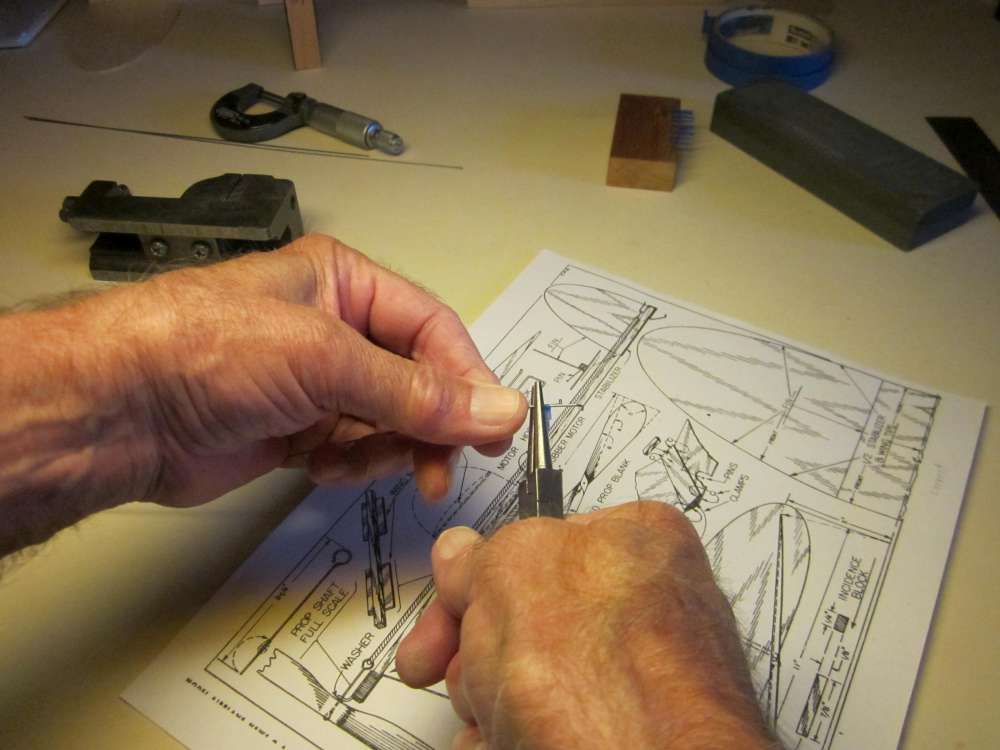
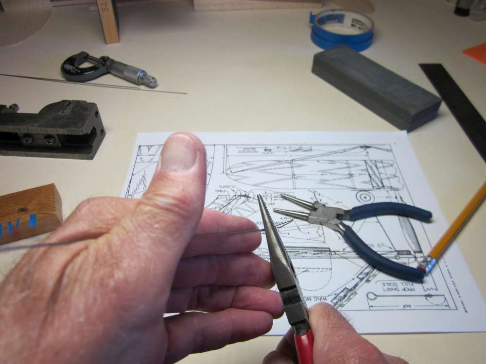
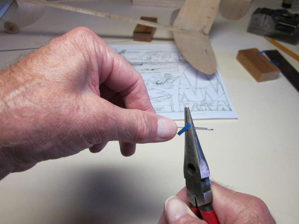
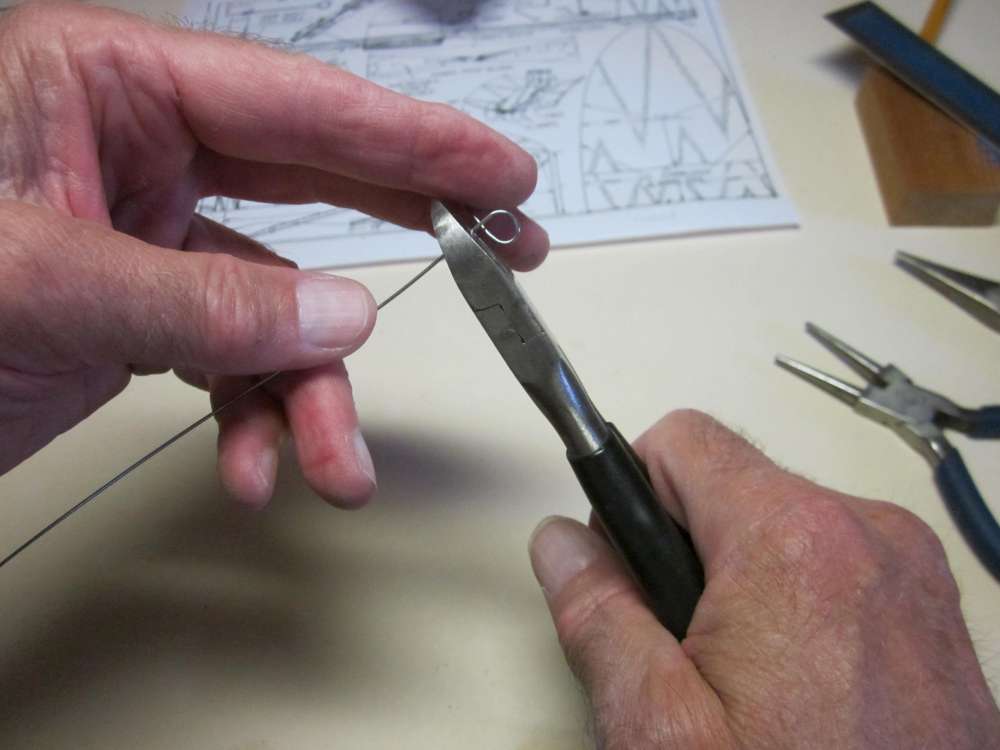
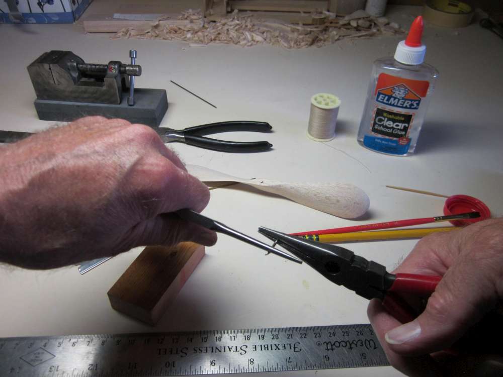
BENDING WIRE
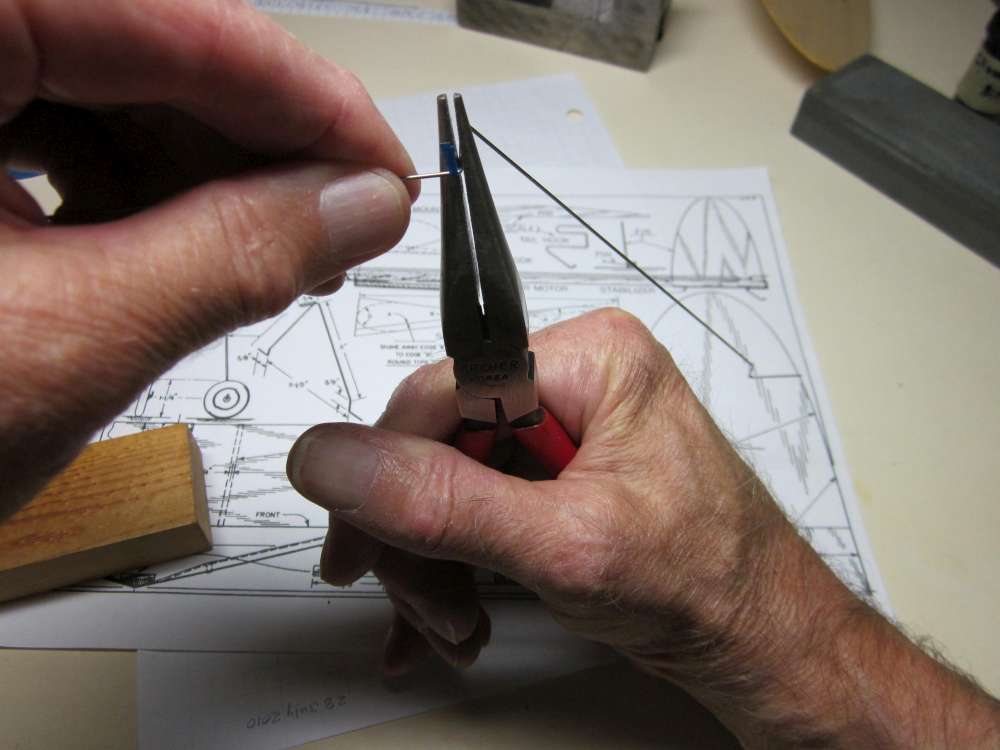
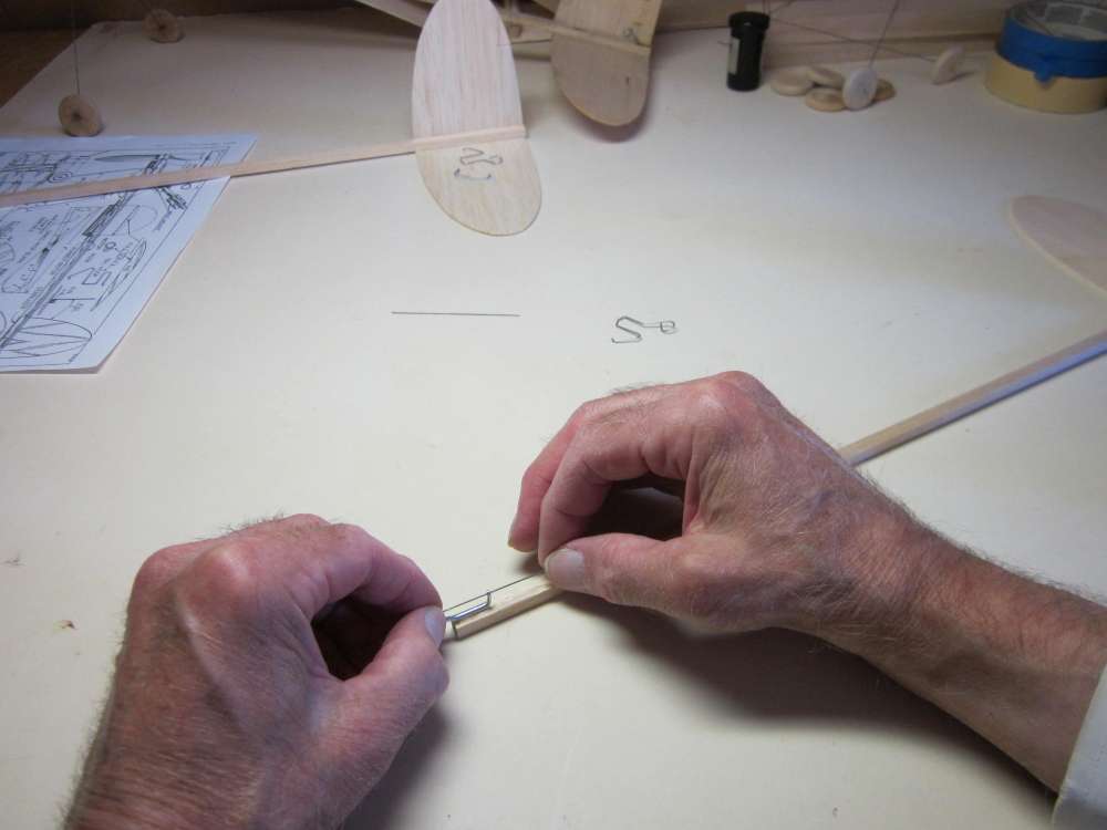
When we bend wire with pliers, the bent wire ends a little way off the face of the pliers. We must know how to place the pliers on the wire to get the bend where we want it. We do a test to find out how to do that.
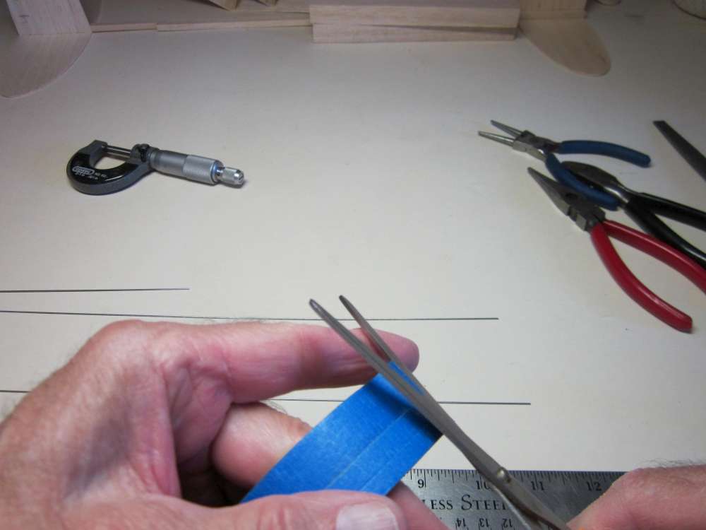
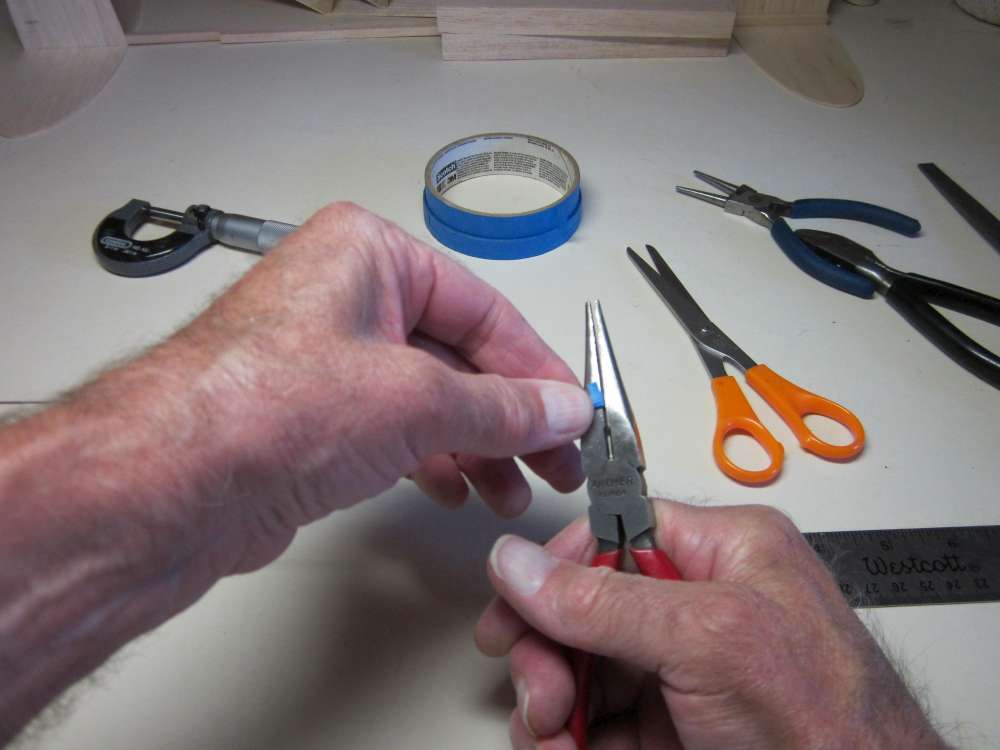
We will mark the location for bending with tape. Cut a thin strip of tape from the end of the roll. Cut several at once and stick them to a block of wood.
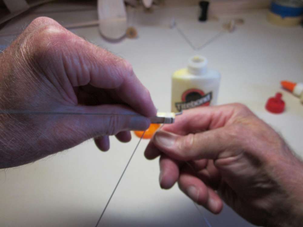
Put the tape across the wire.
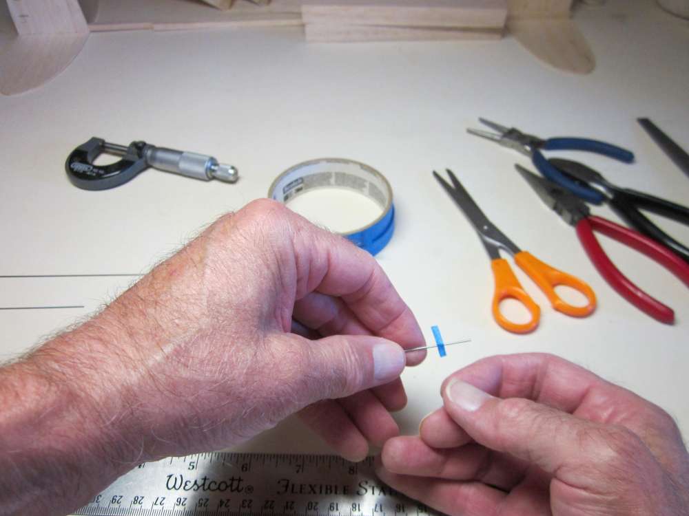
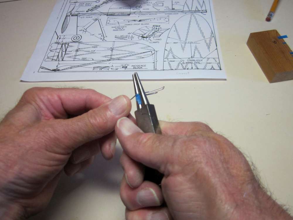
Fold the tape over the wire and slide it to exactly 1/4″ from the end. Squeeze the tape tight around the wire.
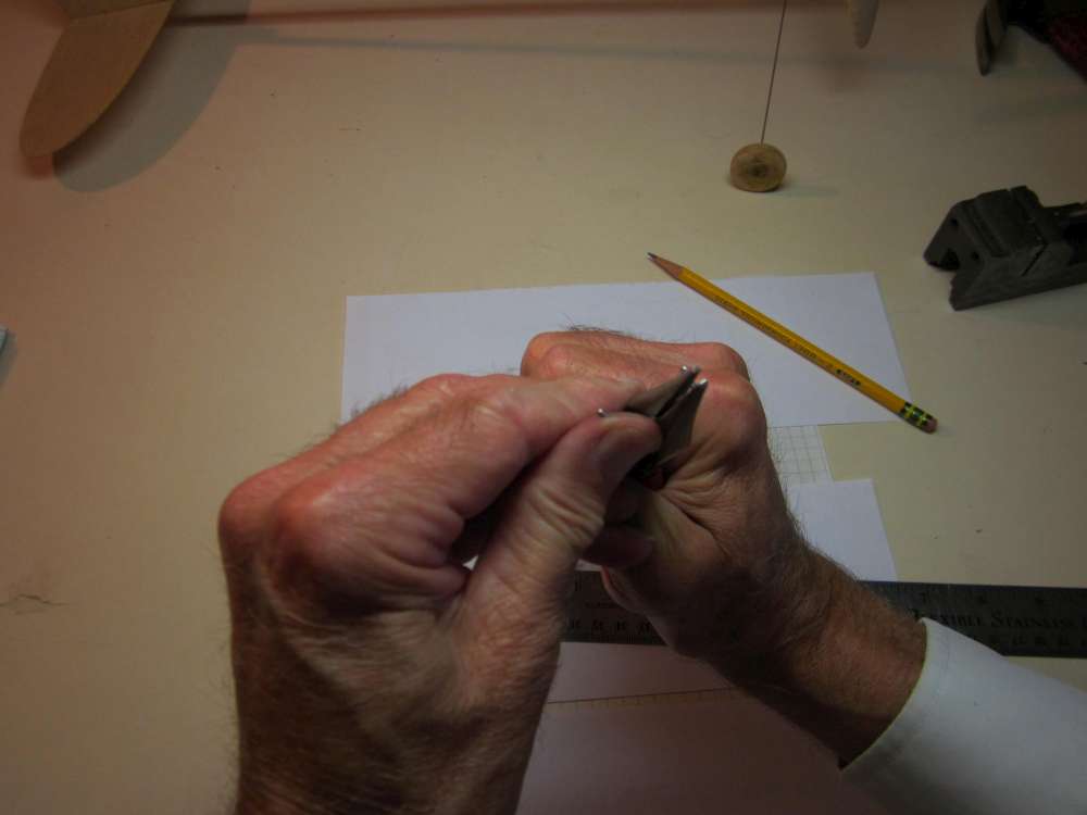
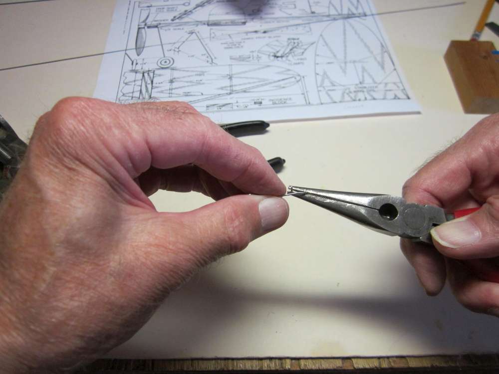
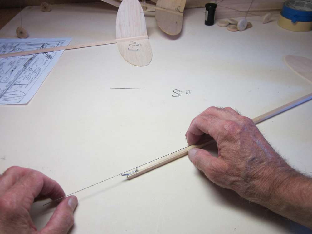
Grip the wire in the pliers with the face of the pliers against the edge of the tape.
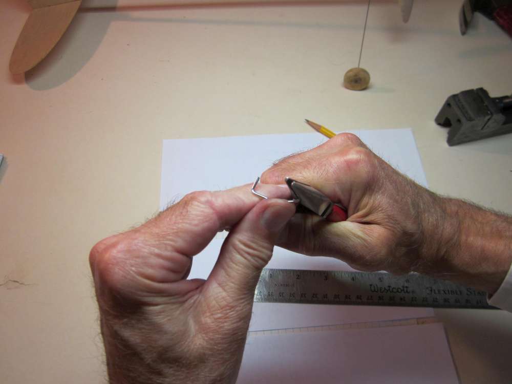
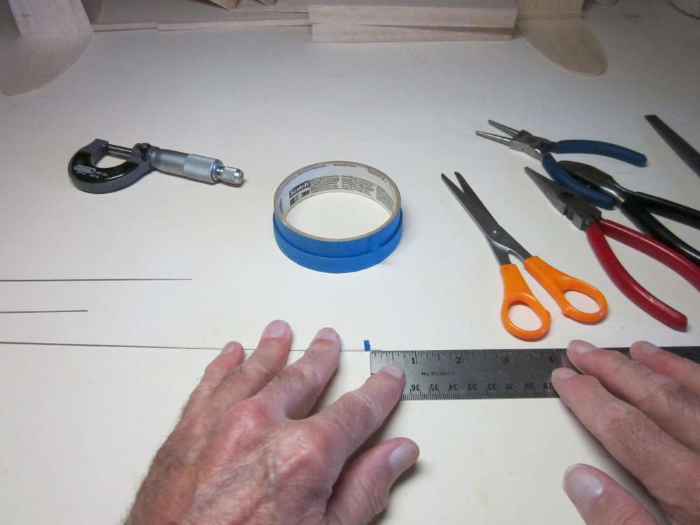
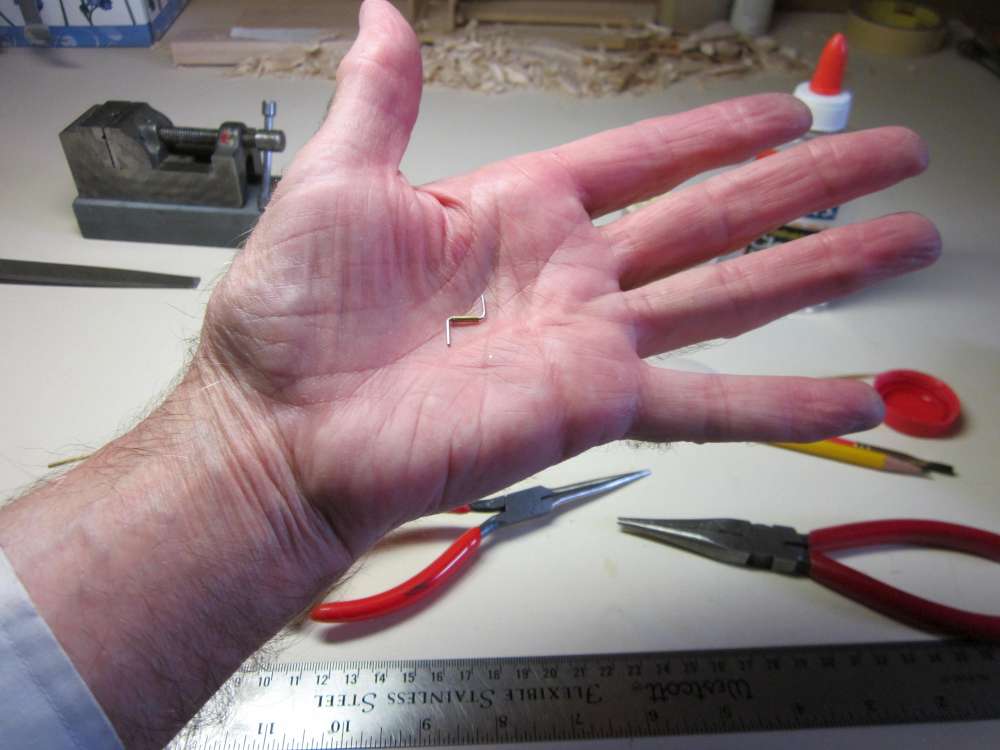
Bend the wire to a right angle. Notice how the wire does not lie flat on the face of the pliers.
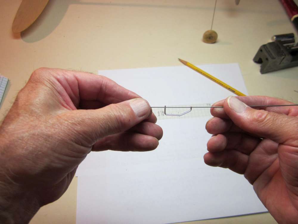
Measure the length of the bent end. The end was 19/64″ away from the outside face of the wire. Draw a little diagram and do some arithmetic and we see that the center of the bent piece was 1/32″ past the edge of the tape. This is 1/32″ diameter wire. This tells us that the bent piece will be one diameter past the place where we put the face of the pliers. We should place the tape edge one diameter back from where we want the bend.
Bent wire will spring back, so you must over bend a little to get it where you want it.
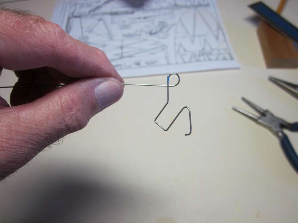
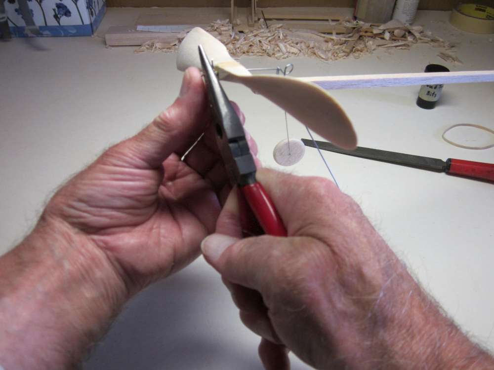
TAIL HOOK
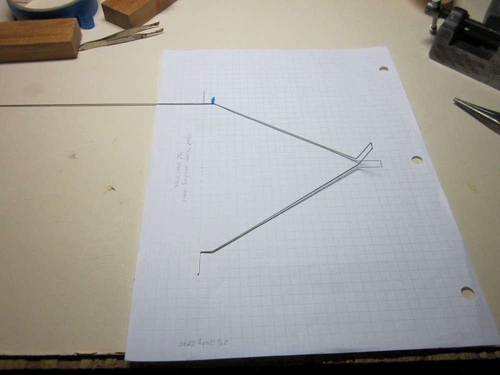
The tail skid and motor hook are made from a single piece of 1/32″ diameter steel wire. It is shown full size on the plan, where it is called the tail hook.
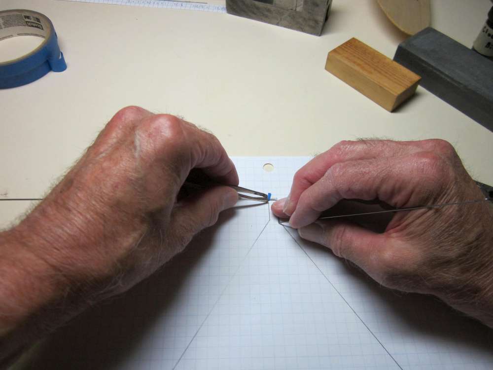
Start by bending the little curve at the end of the skid with round nose pliers. (No photo). Place the wire over the plan and slip the tape, sticky side up, under the wire at the end of the straight piece.
Put the round nose pliers over the edge of the tape and bend the wire on a 3/32″ diameter circle to a 45 degree angle. You will need to bend more than that, because the wire will spring back. Keep all parts of the wire in the same plane. Line this bend up with the previous one by keeping both in the plane of your eye. But be careful to not poke yourself in the eye with the wire.

Make the next bend as shown on the plan.
This is a right angle bend. Keep all parts of the wire in the same plane. Line this bend up with the previous ones. That is easy to do if you put your eye in the plane of the parts. (The camera lens is a little off my line of sight.)
Check it against the plan.
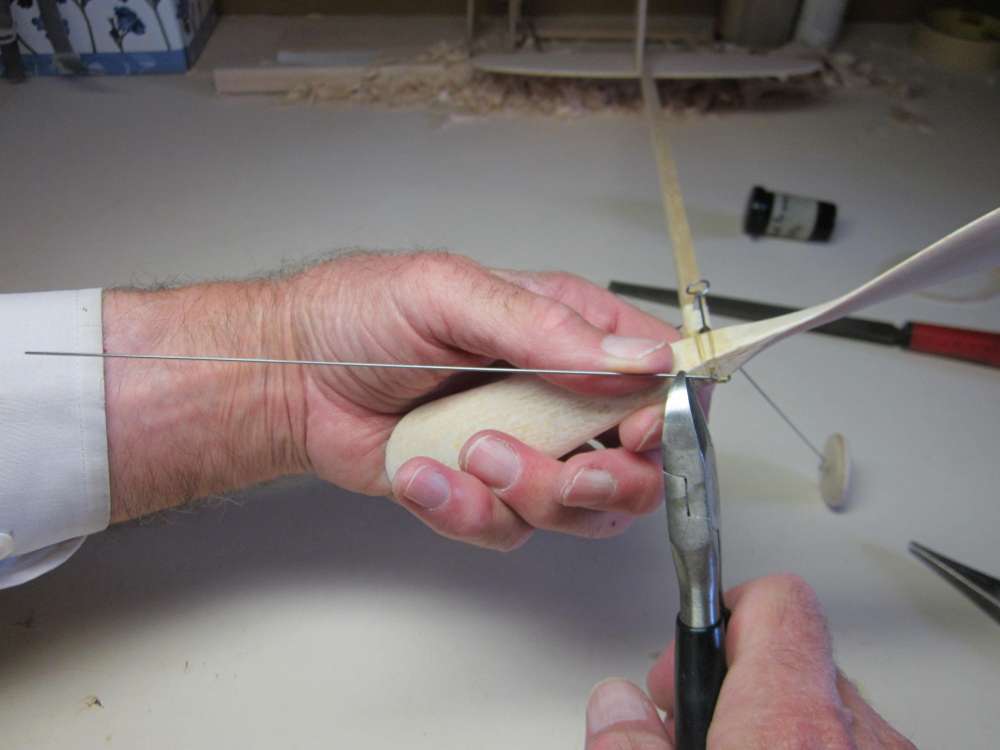
For the next bend, set the tape to match the thickness of the stick and tailplane. This will be a right angle bend.
Get the plane of the bent pieces in a plane perpendicular to the edge of the pliers.
You don’t have much leverage here, so use a block of wood to get a good right angle bend.
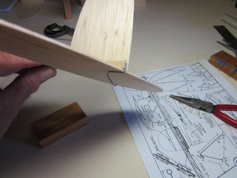
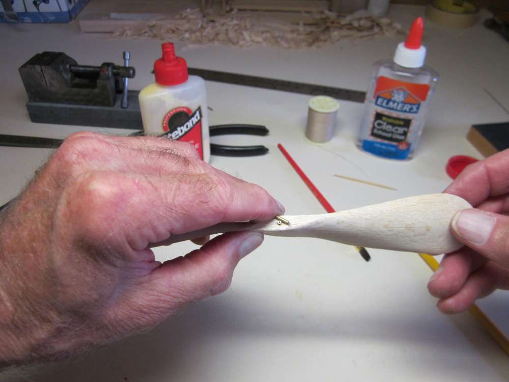
Check for a snug friction fit.
Another way in which my construction differs from the original design is in the form of the motor hook. The original hook lies right on top of the stick. The wound motor knots rub on the stick. Also, the open end allows the unwound motor to come off the hook, putting the plane out of trim. This shows I used a right hand pigtail loop offset above the top of the stick.

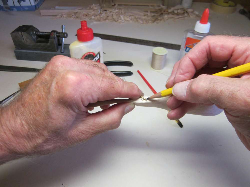
Mark the position for the next bend 1/2″ from the last one. This will be a 45 degree angle up.
Make the bend, keeping all parts of the wire in the same plane. Line this bend up with the previous ones.
Looks like that.

The loop begins 5/16″ above the stick. We are aiming for a 1/4″ loop centered 1/4″ above the stick.
We want a right handed pigtail. Bend the wire downward and coming toward you.

Bend it until it crosses over itself at approximately a right angle.
It should look like that.
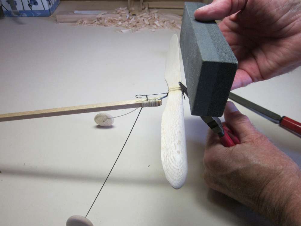
File off any sharp edges and round the end of the wire. This end will be in proximity with tightly wound rubber and we don’t want any scratches.
The pigtail will extend out away from the fin. The overlap will prevent the O-ring from coming off when the motor goes slack.
Adjust the gap so the O-ring slides in with very slight friction.
Check the fit of an O-ring. It should slip in easily with very slight friction. We don’t want to struggle getting it through the gap with a fully wound, lubricated motor in our hand. We also don’t want it to simply fall out when it is unwound.
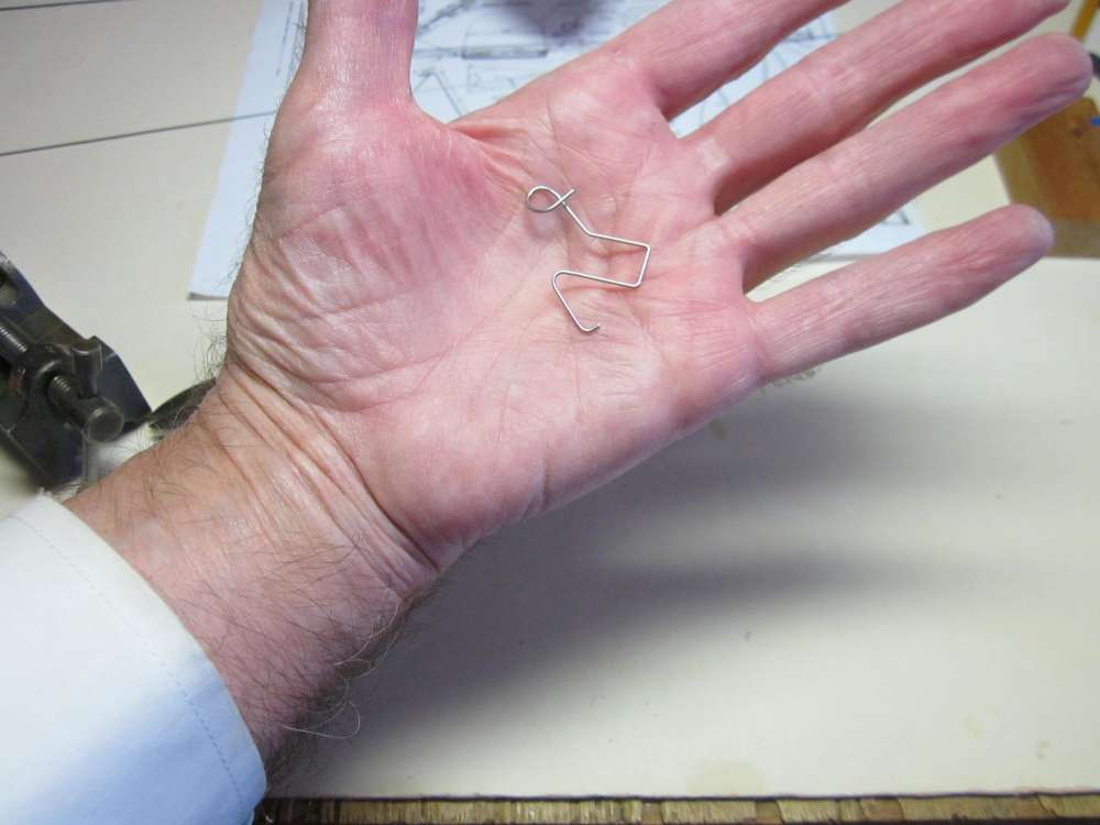
The finished tail hook.
The tail hook is glued to the back end of the stick.
Run a 1″ long bead of glue along the top center of the stick.
Run a 1″ bead of glue along the center line of the tailplane.
Slide the tail hook into the glue. (This one was a bit loose, so the end was bent to narrow the gap.)

Press it firmly against the end of the stick.
Spread glue to surround and cover the wire on top of the stick.
Do the same on the bottom. Adjust the tail hook to be centered on the stick. Set it aside to dry.
LANDING GEAR
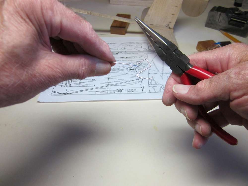
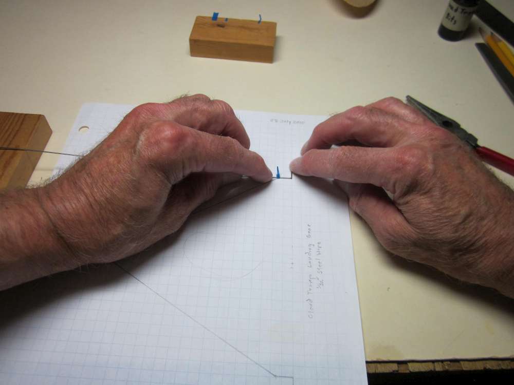
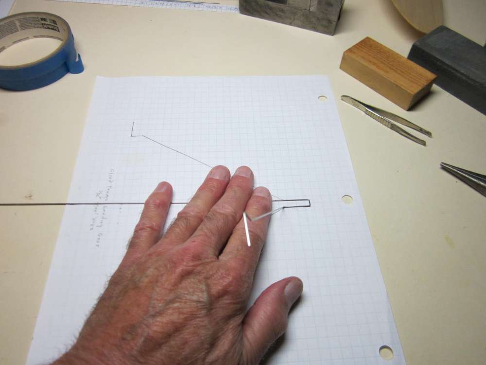
The landing gear is made from 1/32″ steel wire. The dimensions are shown on the plan, except for the width in the center, which must fit under the 1/4″ wide stick. If we add these dimensions together, we get a total of 13 3/4″. Start with a piece a bit longer. (If you start with the exact length, start in the center. The Vintage Model Company instructions tell how to do it that way.)
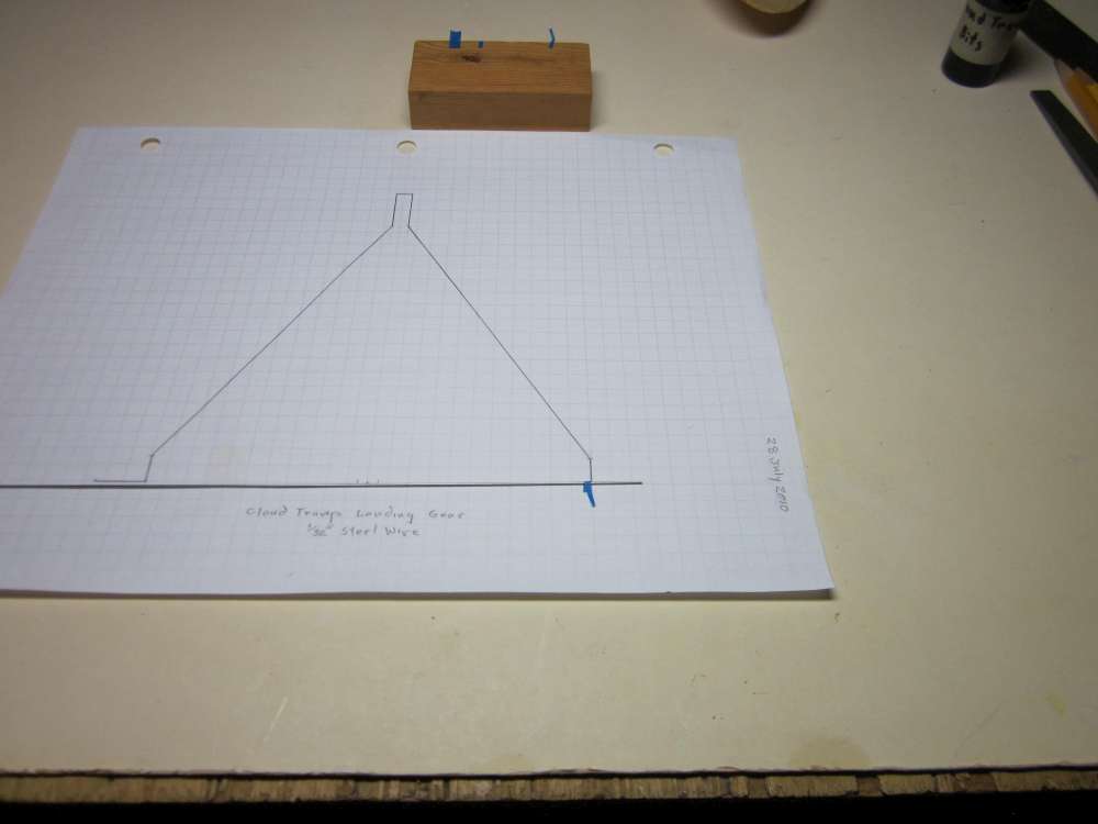
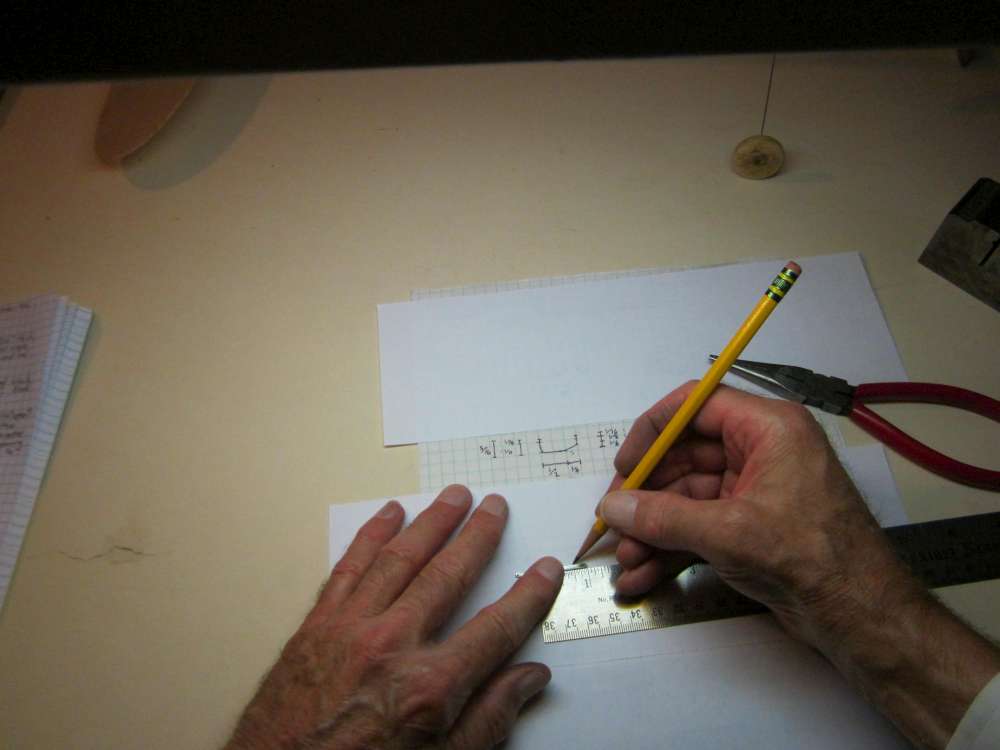
Start by making a drawing of the landing gear. The necessary dimensions are given on the original plan, except for the 1/4″piece that goes across in the center. All of the pieces lie in the same plane except for the three pieces in the center that are in contact with the stick. For purposes of our layout drawing, put them in the same plane.
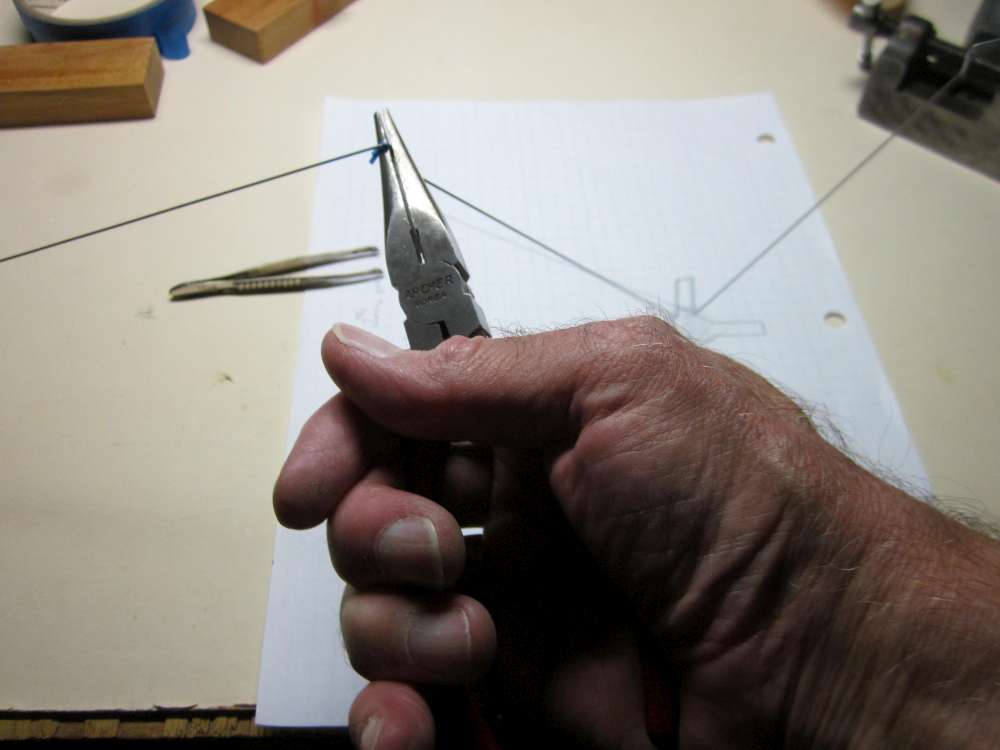
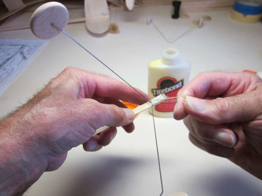
Lay the wire across the base of the drawing with one end at the end of an axle. Place tape at the bend location. This is going to be a right angle bend. (The end of the wire has already been filed round.)
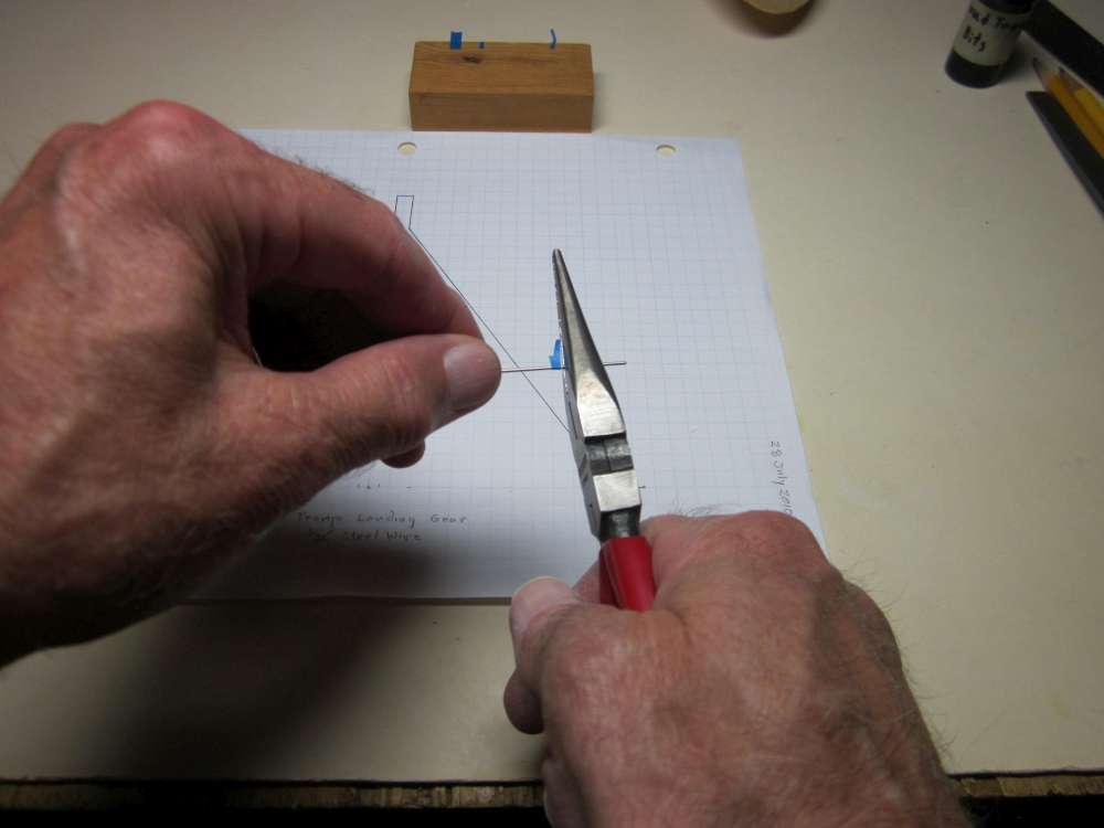
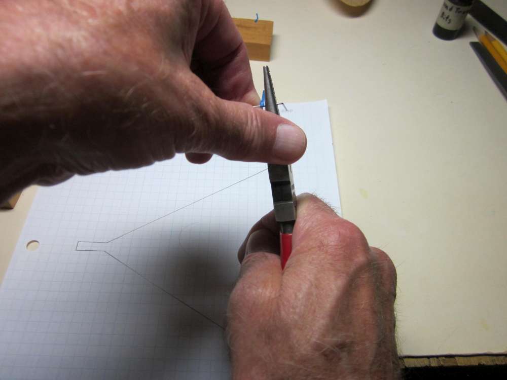
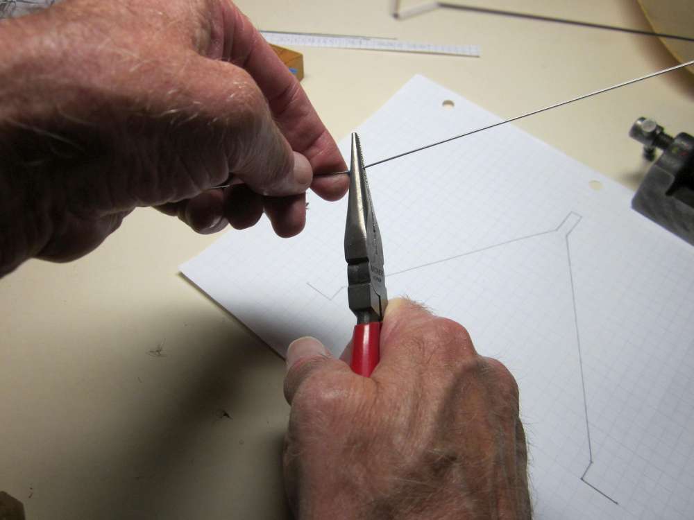
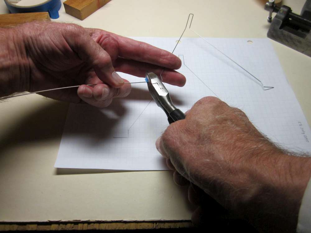
Place the face of the pliers one wire diameter back from the edge of the tape.
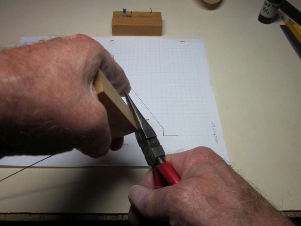
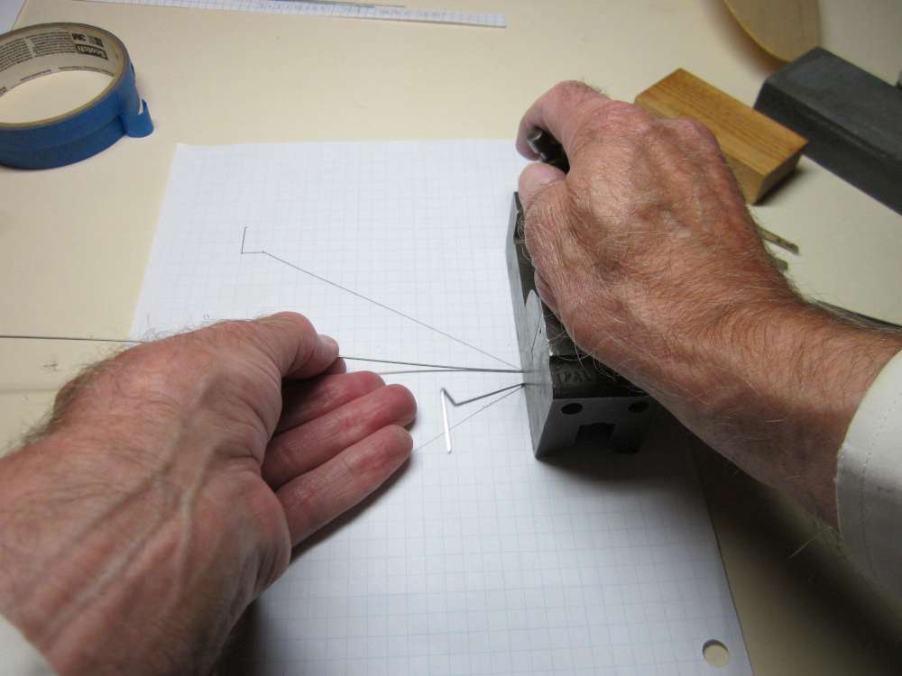
Use a block of wood to bend the wire. The flat face of the block applies uniform pressure to the wire, giving good leverage without putting a curve in the wire we want to keep straight.
Place the wire on the drawing to check the bend.
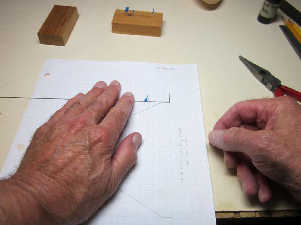
Position the tape for the next bend.
Make the bend, keeping all three sections of wire in the same plane.
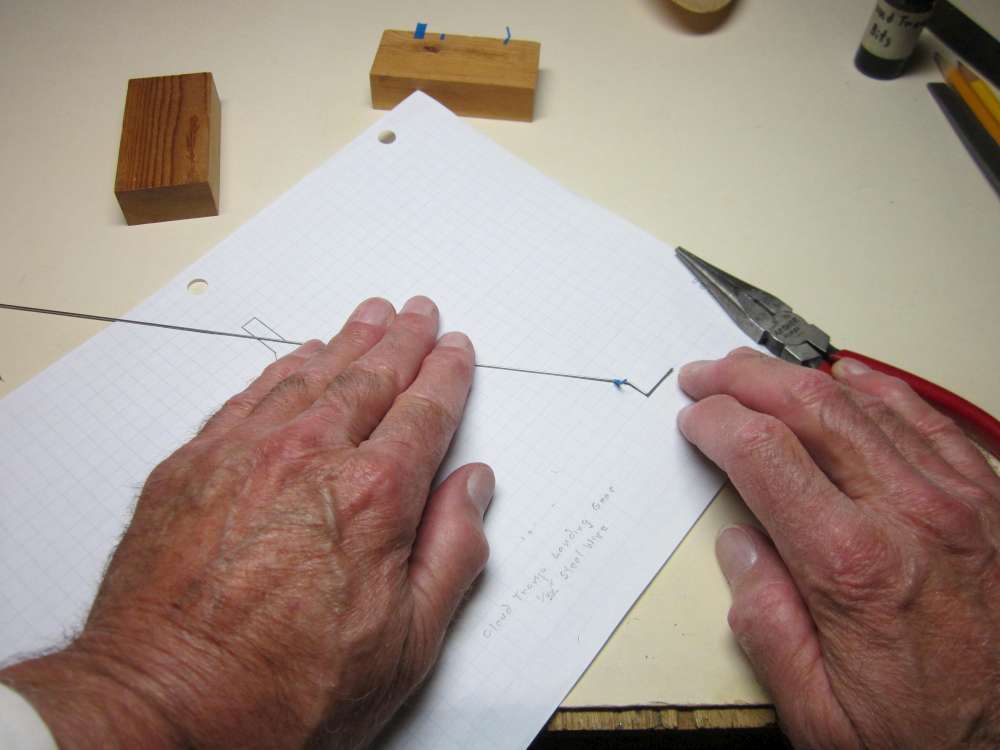
Check the bend, making any necessary adjustments.
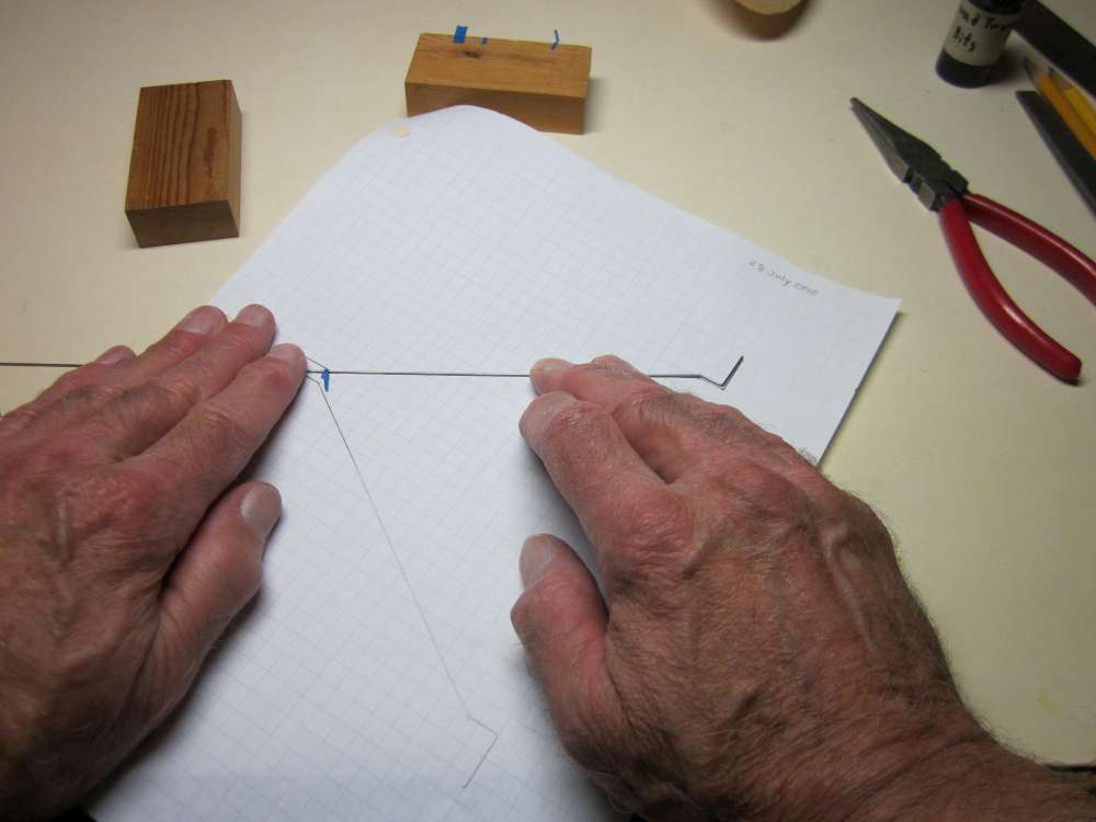
Position the tape for the next bend.
This is a difficult bend because we are going out of the plane of the previous sections. Study the original plan closely and visualize this bend in three dimensions. With the previous section held securely against the drawing, bend the next section up to the position which you visualize. Two thing will help you here; the final position will lie in a perpendicular plane containing the drawing of the section and the forward angle will correspond closely to what is shown in the side view of the original plan.
Check the angle against the plan. Actually, this is not exactly right, the axle would have to be perpendicular to the plan, but it is a good place to start. We can adjust it later.
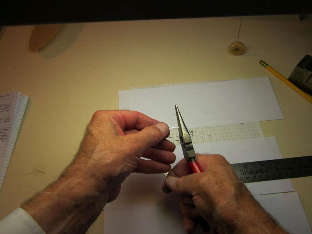
The next section goes across at the nose end of the stick. This is a right angle bend. This section must be parallel with the axle.
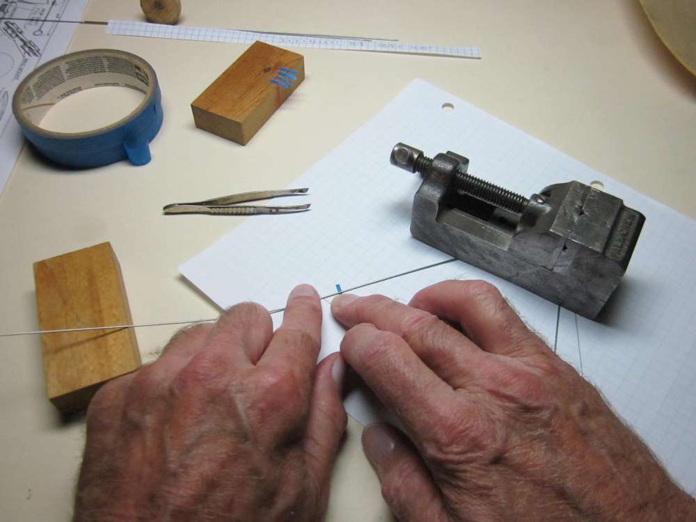
The next is a right angle bend lying in the same plane as the two previous sections. The two side pieces must be parallel and we want the outside faces to be 1/4″ apart. Locate the edge of the tape accordingly.
Check against the drawing. Looking pretty good, some adjustment may be made later.
The next bend is out of the plane. Again, study the plan and visualize the angles. One help is that the landing gear is symmetrical. Make it the mirror image of the previous leg.
Position tape for the next bend.
Make the bend.
Check the bend.

Position the tape for the next bend.
Make that bend. This axle should line up with the opposite axle.
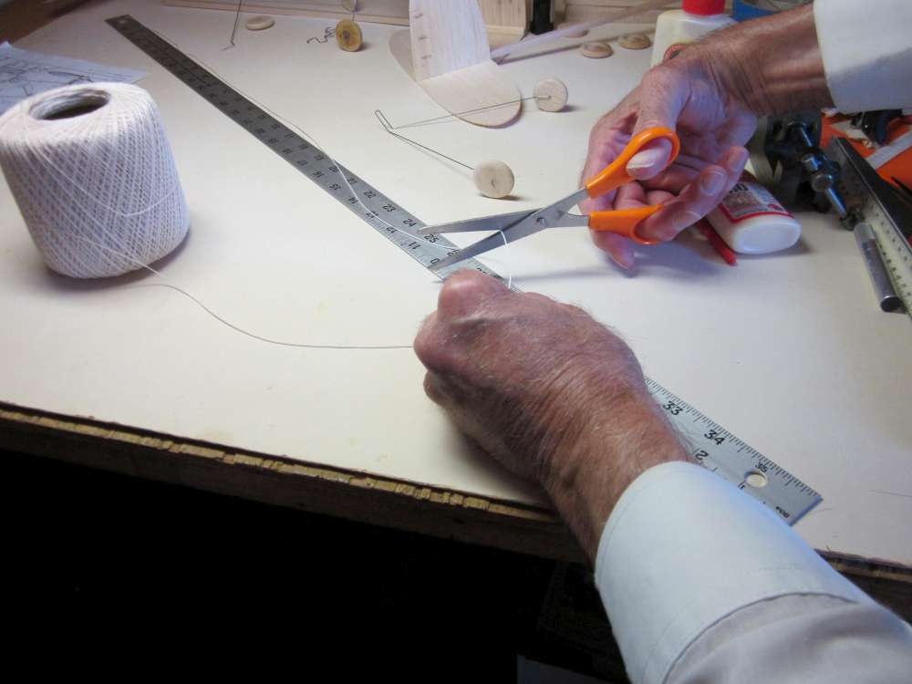
Mark the end of the axle with tape and cut off the excess.
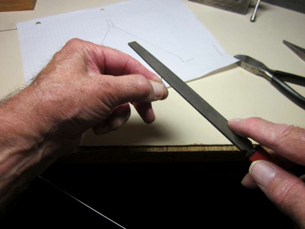
Remove any sharp places and round off the end. Make any necessary adjustments.
Insert the axle into the hub. (There is another way to keep wheels on axles using plastic disk wheel collars.)
Grip the axle close to the hub, leaving 1/8″ projecting beyond the face of the pliers.
It is very hard to bend such a short piece of wire. It must be pressed at an angle against a hard surface to start the bend. We want the bent end to point backwards.
The finished landing gear.
INSTALLING THE PROP BEARING AND LANDING GEAR
Run a bead of glue along the center on top of the stick at the front end.
Place the prop bearing in the glue and press down.
Use a straight piece of wire to carefully align the bearing. I put the shaft parallel with the center line, no side thrust or down thrust. (If you want side thrust, this would be the time to set it, but you won’t know how much you want until you have flown your Cloud Tramp.)
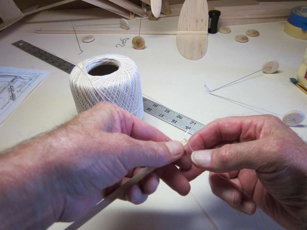
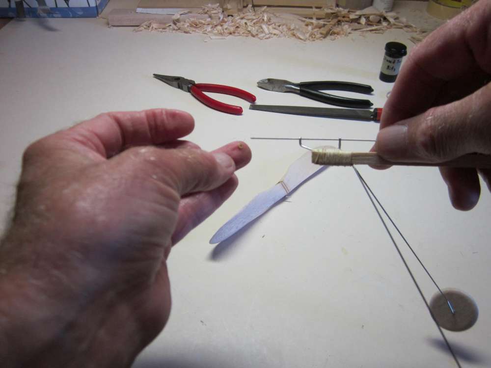
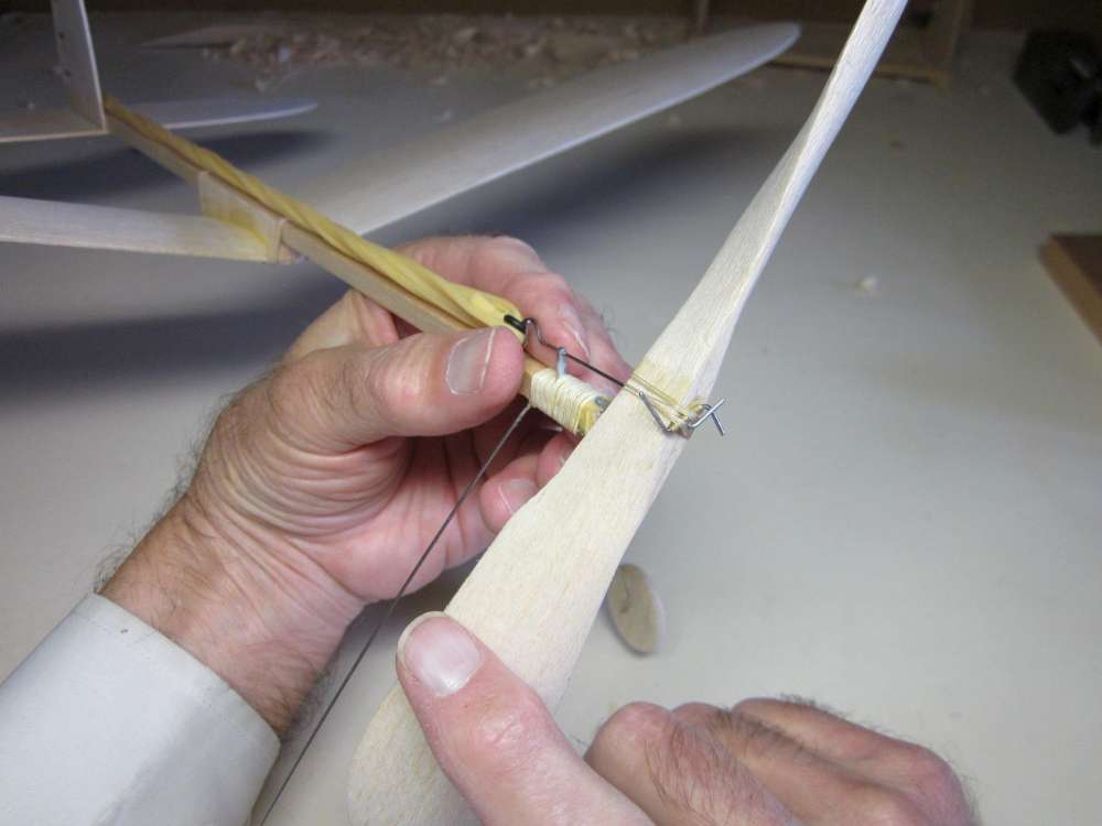
The prop bearing and landing gear are going to be bound to the stick with cotton kite string. The length required depends on the number of wraps, with about 1″per wrap. That in turn depends on the width of the string and span of the wraps. A simple way to estimate the length required would be to wrap string around a piece of 1/4″ square stick the required length and cut off with a little extra. I had 26 wraps or about 26″ of string. The wraps should extend the full 3/4″ length of the landing gear wire in contact with the stick.
Run a bead of glue across the end of the stick.
Wet the end of the string with glue and press it into the glue on the stick. Let the glue dry.
Paint all four sides of the stick with glue to 3/4″ back from the end.
Get glue on top of the prop bearing and on the stick behind the prop bearing.
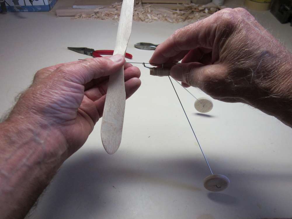
Place the landing gear against the underside of the stick and tightly wrap the string around the landing gear, stick and prop bearing.
Pull the last wrap down into the glue and press it firmly in place. Let the glue get tacky.
Mix some glue with an equal part of water. We want this to soak into the string.
Thoroughly soak the string with this mixture.

The finished wrapping. Let the glue dry.
Cut off the excess string.
THE PROPELLER
There are several options for the 8″ propeller. Both kits referenced above have plastic propellers. If you are not building from a kit, there are several suppliers from whom you can get plastic propellers. These props are generally low pitch. if you want a higher pitch, you can get a larger diameter prop and cut it down to 8″. George Bredehoft also provides a band sawed bow tie balsa prop blank, similar to what is shown on the plan.
I decided to carve balsa propellers for my Cloud Tramps. I wanted it to match what is shown on the plan. The prop shown on the plan is impossible. The drawing contradicts itself.
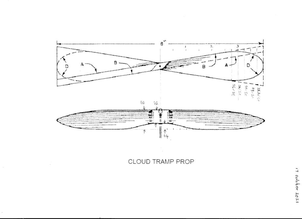
It calls for a sawed prop blank as shown on the drawing. If that was the case, the blade outline would not extend beyond the inner line Edge “A”. The blade outline would lie entirely within the lower surface of the blank. The blade tip angle would be 30.96 degrees and the P/D would be 1.88. The blade outline curve “D” is shown extending to the outer line Edge “B”. The blade tip angle would be 26.56 degrees and the P/D would be 1.57. So which is it? Elsewhere Grant says the optimum P/D is π/2 = 1.57. The drawing implies the prop lies within a 3/4″ x 1 1/2″ x 8″ block. If we use the standard X-block carving method on that block, we would get a prop with P/D = 1.57. That’s what I did and the prop flies the plane quite well. I suggest you use a block of those dimensions from fairly dense balsa, at least 10# density balsa. The prop is the first thing to hit anything and should be strong. The full length motor makes the Cloud Tramp a bit tail heavy, so a heavy prop is a good balance. Once you have your block, head over to our prop carving tutorial. When you have finished carving your prop, come back here to install it on your Cloud Tramp.
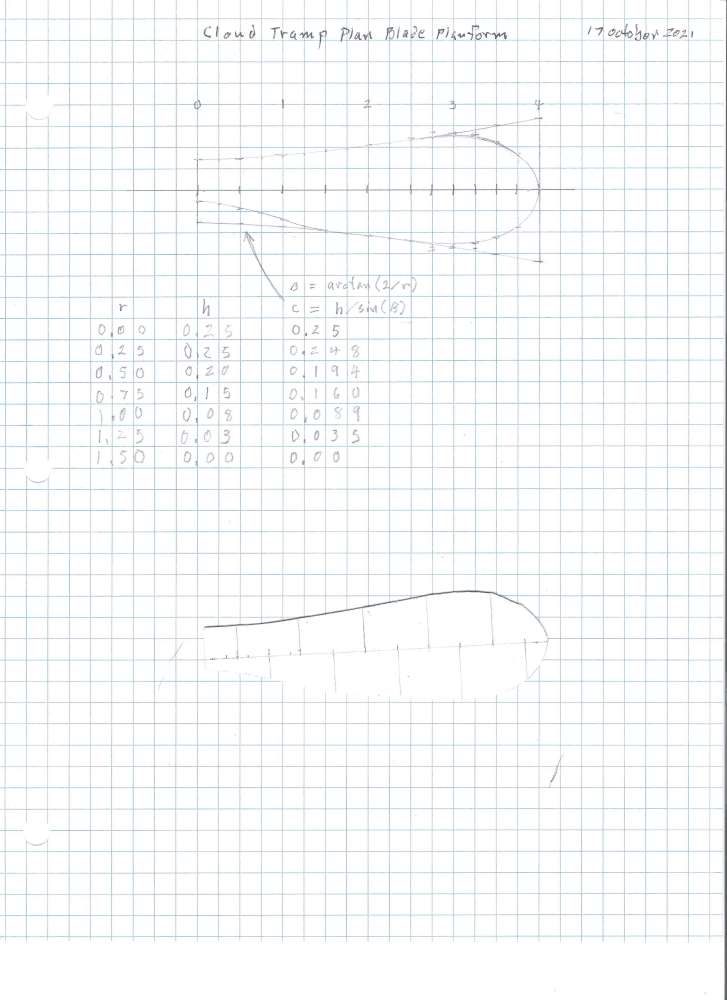
This is the blade plan form that I developed from the Cloud Tramp propeller drawing. If you use this and the above specified block you will get a serviceable prop. You can also use the blade plan form traced from one of your favorite plastic propellers.
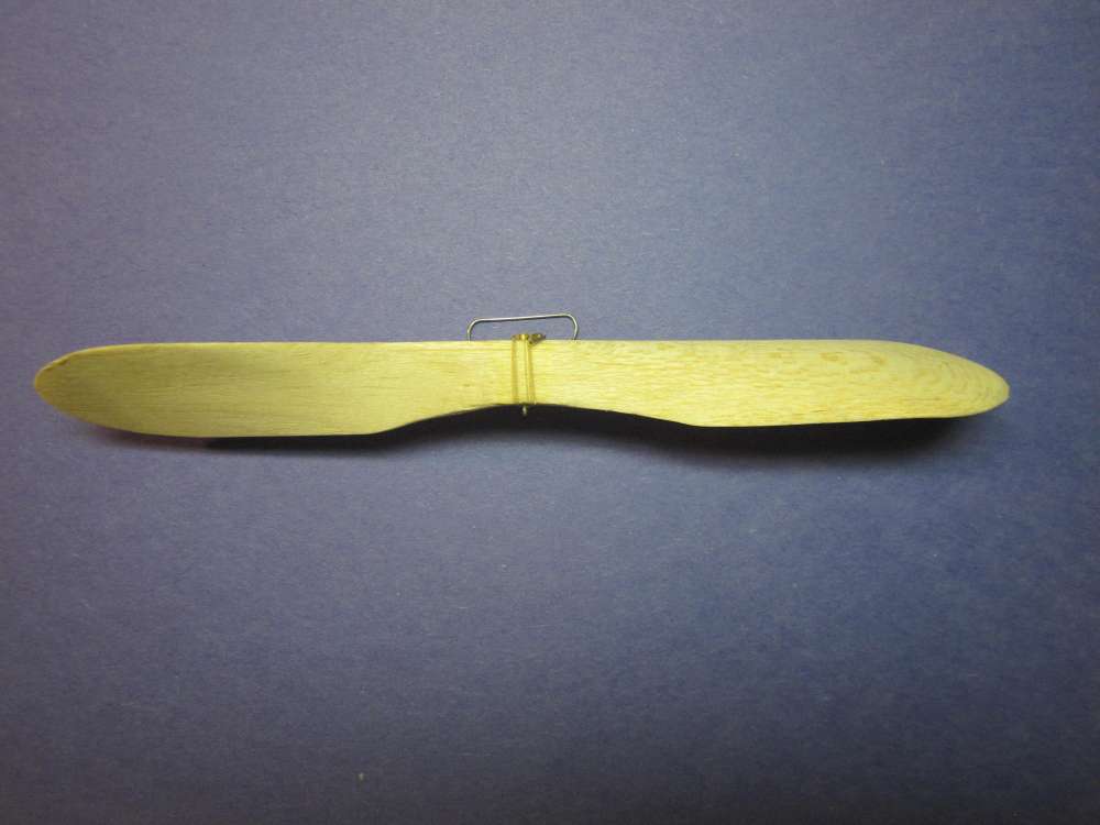
Here is the side view of the resulting prop.
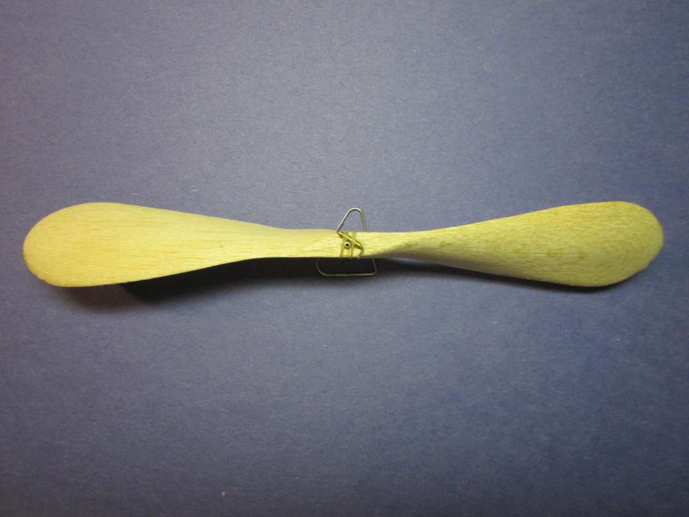
Here is the front view. Pretty good match. This differs from the original prop in that it uses a 1/16″ brass tube for a hub and a freewheeler. This will allow our prop to freewheel. The original was fixed to the shaft.
We start construction of the freewheel clutch by cutting off a 1/4″ length of 1/16″ brass tube.
Next we cut off a 3/4″ length of 1/32″ steel wire.

File down the sharp edge of the cut wire.
Round both ends of the wire.

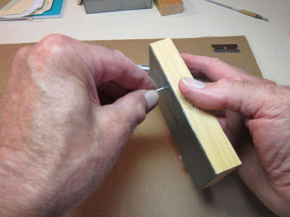
Grip 7/32″ of the wire in the pliers.
Use a block of wood to bend the remaining part of the wire over to a right angle.
Insert the long end of the wire through the brass tube.
Bend the other end over at a right angle, keeping it in the same plane as the other parts of the wire.
The completed mechanism.
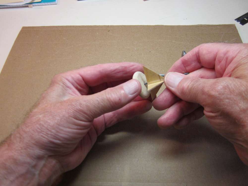
Place it on the face of the prop so one leg of the wire lies flat along the hub and the other end sticks straight up.
Mark where the brass tube is in contact with the prop.
Put a bead of glue along the mark.

Put the brass tube in the glue.
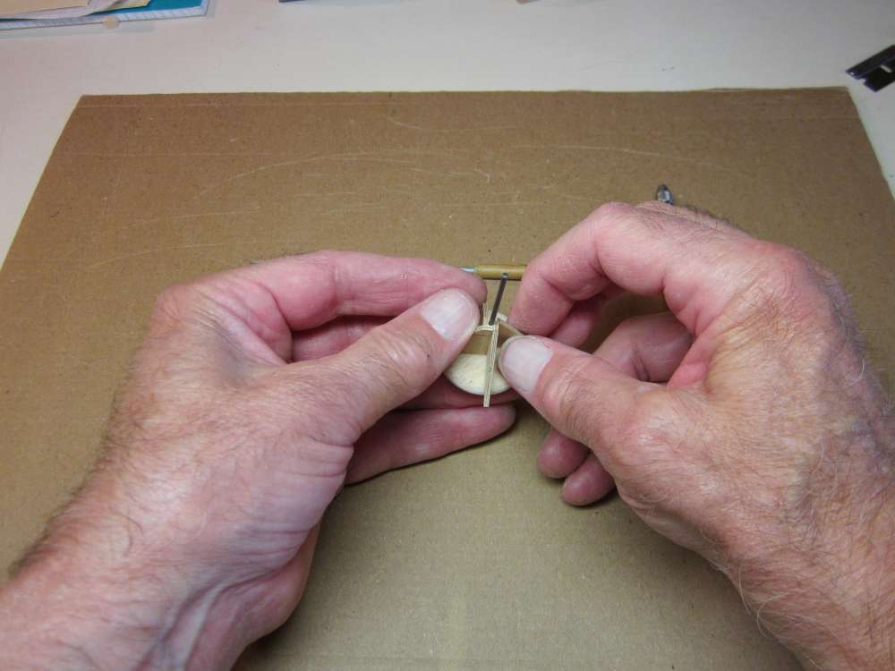
Glue a piece of thread on the hub so it aligns with an end of the brass tube.
Let that glue dry.
Wrap thread around the brass tube and the prop to secure the tube.
Paint glue over the thread and cut off the loose end of the thread. Let that dry while we bend the prop shaft.
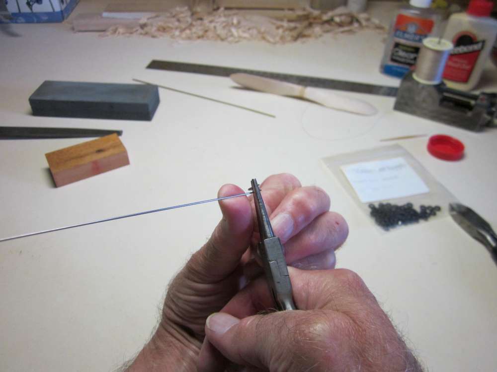
The prop shaft is made from 1/32″ steel wire. Grip the wire about 1/4″ from the end with the round nose pliers. We want to make a 1/4″diameter loop. The wire will spring back, so we wrap it around a smaller diameter on the pliers.
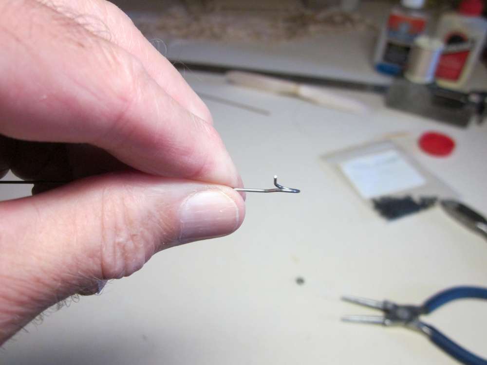
We want a right handed pigtail. We want the end to overlap the loop.
Bend the straight part back so it projects through the center of the loop.
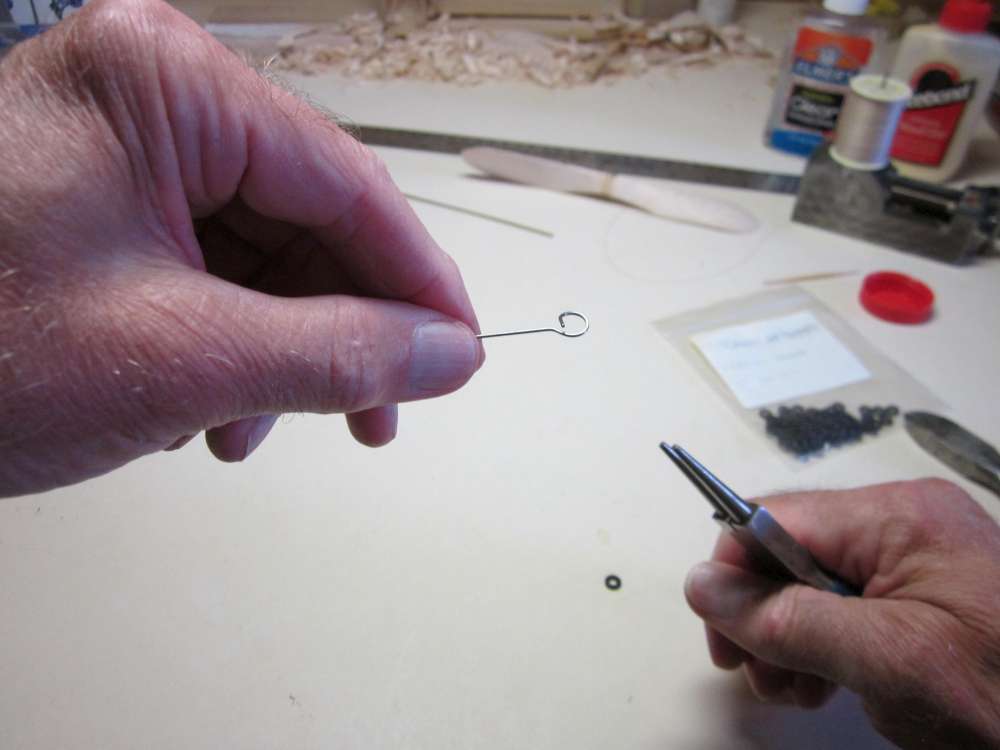
It should look like this when it is done.
most of the loop should lie in the same plane as the main shaft, but the end of the loop must be bent up to allow the O-ring entry.
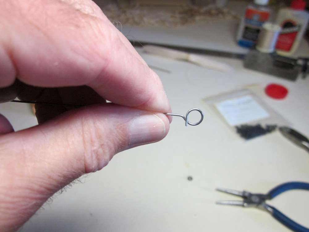
The right handed pigtail keeps the right handed twist in the wound motor from twisting off the hook and the overlap keeps the O-ring from slipping out after the motor has unwound.
Check that the O-ring is a slight friction fit.
The glue should be dry on the prop by now, so we can cut off the excess thread.

Put the straight end of the prop shaft through the bearing from back to front.
Yeah, the landing gear legs need to be bent forward.
Put two brass washers on the shaft.
Put the prop on the shaft. Slide the shaft through the prop and pull it up snug.
Bend the shaft to a right angle.
Cut the bent end off to a 1/4″ length.
Remove any sharp points and round off the end of the shaft.
When the motor turns the shaft, the end engages the forward leg of the free wheeler and pushes it until the back leg presses against the hub.
When the motor is no longer turning the shaft, the prop turns in the wind until the shaft knocks down the free wheeler and it passes underneath without engaging.
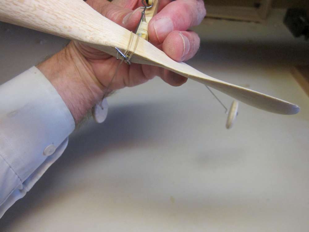
INSTALL THE WING
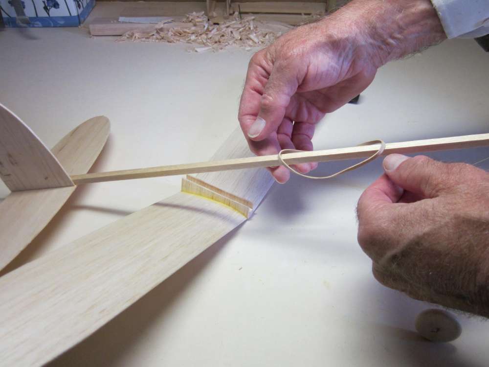
Drop the 2 1/2″ rubber band over the stick so it hangs down on each side.
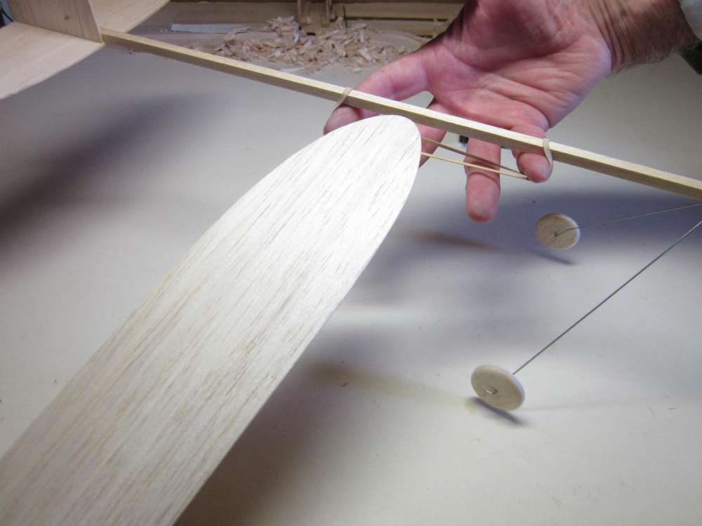
Put two fingers through those loops and spread them apart enough to fit the wing through the gap. Be sure the wing is correctly oriented, top up, leading edge forward.
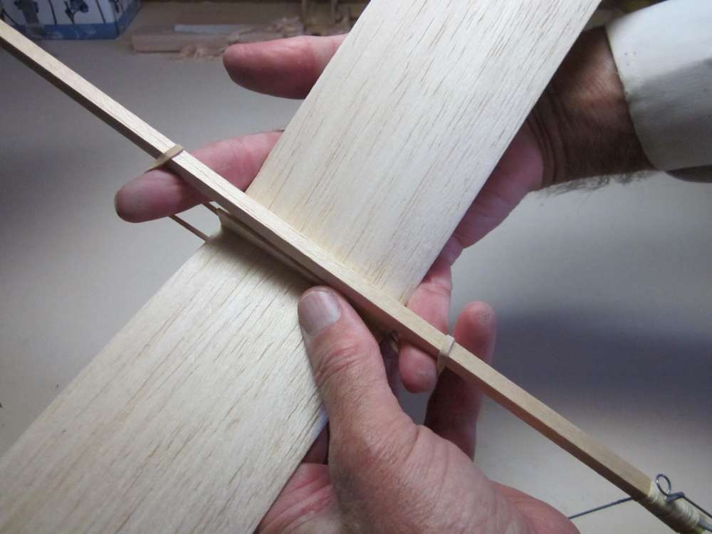
Slide the wing through until the slot in the saddle aligns with the stick.
Fit the stick into the wing saddle.
Adjust the rubber band so it is tidy.
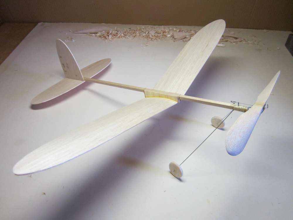
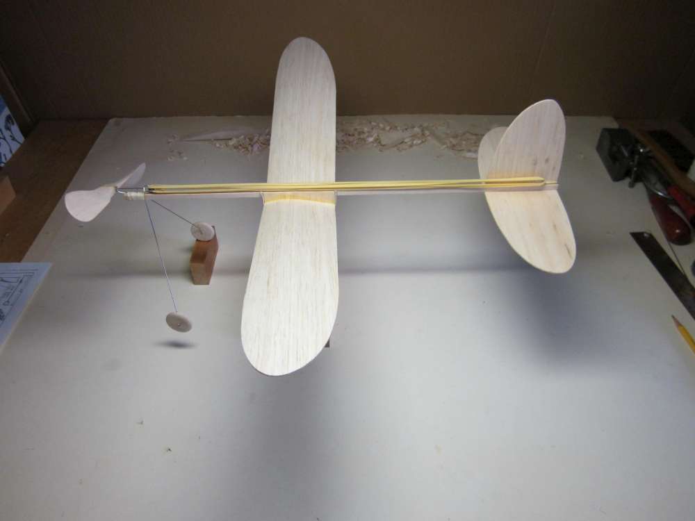
The completed airplane. This is a good time to weigh the airplane. Two of mine weigh 17.3 grams and 18.6 grams. We still have a motor to add.
THE MOTOR
I like my motor lengths to be twice the distance between the hooks. Anything longer gets difficult to manage. In this case, that distance is 16″, so the motor will be 32″ long. The Cloud Tramp likes the torque produced by four strands of 3/32″ rubber strip. That means we need 4 x 32″ = 128″ = 10′ 8″ of 3/32″ rubber strip. Four strands requires the 3/32″ strip to be passed twice through the 1/8″ O-ring before tying the knot. You might like to braid your motor, too. Our tutorial on making rubber motors tells you how to do it, adjusting for the different dimensions of the motor.
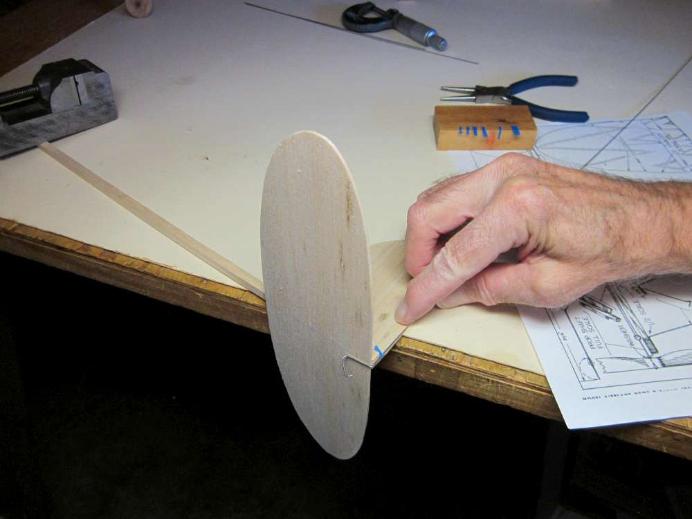
BALANCING
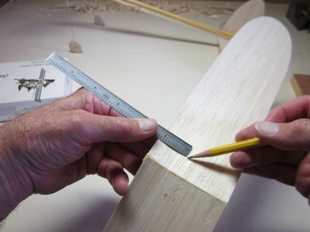
An airplane must be balanced properly in order to fly. The Cloud Tramp likes to balance at the high point of the wing camber. Mark points 1 1/16″ back from the leading edge under each wing on each side of the center line.
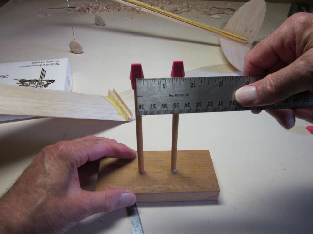
Those points should be as far apart as the supports on your balancer.
Put the motor on the plane and double it so it doesn’t flop around. Put the plane on the balancer with the marks on the points. Move the wing until the plane balances on the marks. This is easier to see if you have the airplane pointing over the edge of your worktable, so you can get down and look up at the marks.
When you have it balanced properly, put a mark on the stick at the leading edge of the wing so you can get it back in the same place later. You may want to move the wing after flight testing, but this first mark will serve as a benchmark
FLYING
The Cloud Tramp needs a pretty large field to fly in. You want it flying in no less than about 50 foot diameter circles, preferably larger. Look on Google maps for a large field nearby. The Cloud Tramp can fly pretty high, maybe over 100 feet. Wind speed is greater at higher altitudes. Consider wind drift when launching your plane. There is less chance of losing your Cloud Tramp if you fly on windless days, or fly on a field that has a lot of downwind room. Also avoid trees, buildings or other obstacles that might catch your plane. It is a good idea to have a retrieval pole handy.
For best results, the motor should be properly lubed and stretch wound. Estimate maximum turns with a formula, but learn to judge motor tension by hand. Maximum turns by formula is only a guide. Pretty good rubber in the dimensions given may take as much as 2,700 turns.
I fly alone, so I use a foot stooge to wind my motors.
I see many people saying they need to use “downthrust” to control stalling or zooming. If you need to use downthrust, there is something wrong with your Cloud Tramp. It flies fine with the thrust line as specified. Downthrust wastes energy, directing it downward. You may have the wing too far forward, the center of gravity is too far aft on the wing. Try moving the wing back in 1/4″ steps until it flies properly. If that doesn’t work, you may be using a too thick motor. Every airplane has a power to fly requirement. If you overpower it, it will power stall or zoom. The cross section of the motor should be in the vicinity of four strands of 3/32″ rubber strip. More power will not give you more duration. It will burn your limited energy supply more quickly. Power is the rate of use of energy. More power uses the available energy more quickly, resulting in less duration. There is an optimum length and cross section of rubber for each airplane. Duration falls off very rapidly with any deviation from that optimum.
Here is a video of my Cloud Tramp flying.
HALF SIZE CLOUD TRAMP
If you want to fly in a smaller area, try a half size Cloud Tramp.
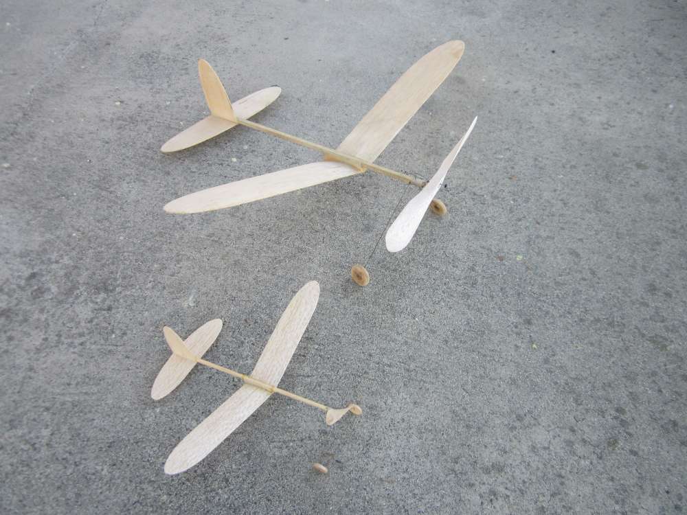
The part patterns are taken right off the half size plan. The sheet parts are made from 1/32″ sheet balsa. Everything else is made to half the dimensions.
You don’t get to see much of it flying here, because I had to run after it, shaking the camera. As it flew over a group of dogs, one of them saw it and called out “Bird, bird!” and the whole pack ran after it. I had to pass them and get to the plane first.
Absolutely love your wing mount mod! Gonna try this with some laser cut templates/jigs for beginner group builds.
Thanks
Doug Griggs
George Bredehoft produces a short kit of the laser cut parts. One minor difference is his wing mount side plates are 1/8″ thick balsa, where I use 1/16″ wood. You can get the short kit here:
https://volareproducts.com/blog/?product=cloud-tramp-short-kit
There is also a 1/4″ discrepancy in the height of the fin. I made my fin to extend across the 1/4″ stick, as shown on the plan. George uses the span that is called out in the instructions, which is 1/4″ shorter. It probably doesn’t matter; the short one is a little bit lighter.
I don’t use the wing ribs. The ribs may be glued to a board to make the form for wet forming the wings.
If you buy the kits, tell George I sent you.
Great presentation and seems much more meticulous than my building technique.