After zoom-chatting with Gary Hinze and Richard Barlow I got the bug to make up some Cloud Tramps. Richard encouraged me to get others in on it, particularly children and I think that’s cool so I’m making a fleet.
Here’s quick montage of the fun time I’ve had so far with this project.
This article shows how I used the conveniences of CNC machining and 3D printing to create my fleet of Cloud Tramps, a legendary design by Charles Grant.
What’s a CNC? Computer Numerical Control. It’s a rotary cutter (like a Dremel) that is controlled by a computer. CNC machines also include lasers and 3D printers.
I used InkScape for creating the balsa parts. It’s a free vector graphics editor similar to Adobe Illustrator. Here’s an InkScape tutorial to check out how easy it is to use.
Designing in software is called CAD (Computer Aided Design). Inkscape is not known as a CAD software but it is fine for this type of “2D” work. This method is often referred to as “2.5D” design since you design in two dimensions but after assembly you have a three dimensional object. In a way this is a tradition for model airplane design because most of the materials come in sheet.
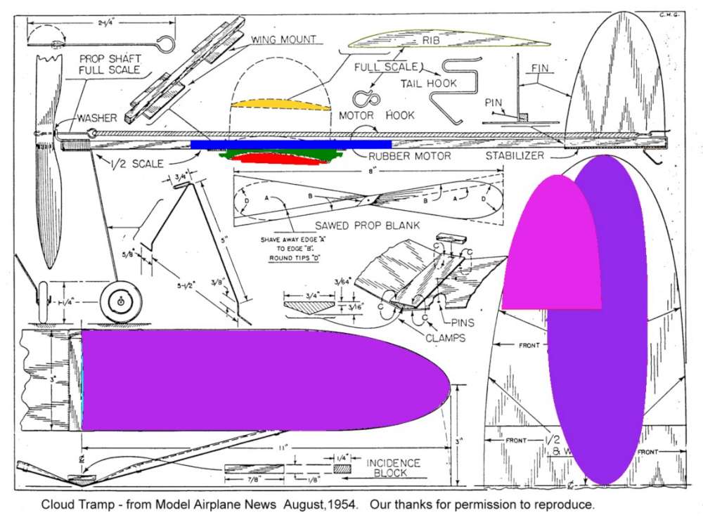
I opened up InkScape and dragged the original plan from 1954 (in JPG format) onto the drawing canvas. I then stretched it till it was at the right scale and then traced the parts. You can download the files at the bottom of this article.
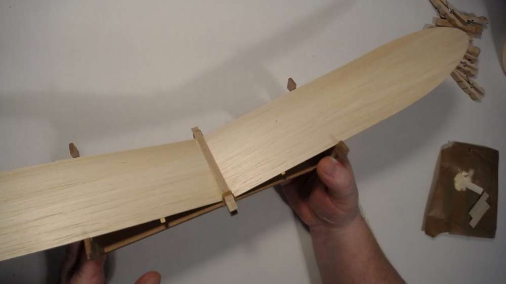
I wanted a constant wing camber all the way to the root like Richard and Gary had done on their models. I think it makes the wing more rigid, resistant to warping and increases the charisma of the model. I devised a system that’s easy to assemble and easy to attach to the model.
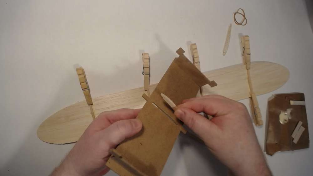
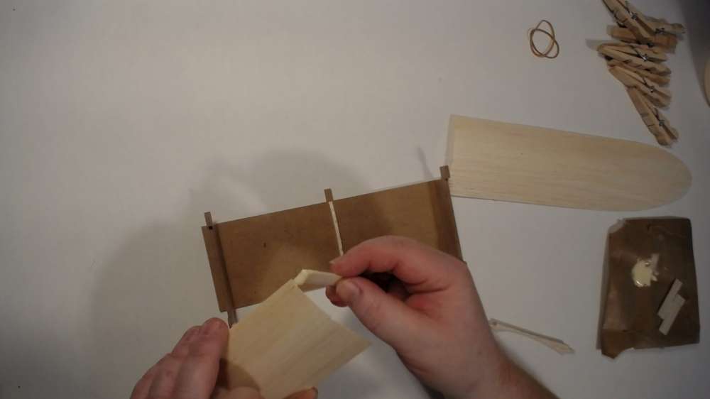
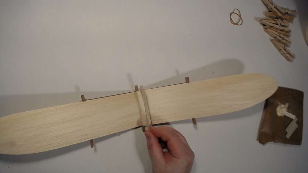
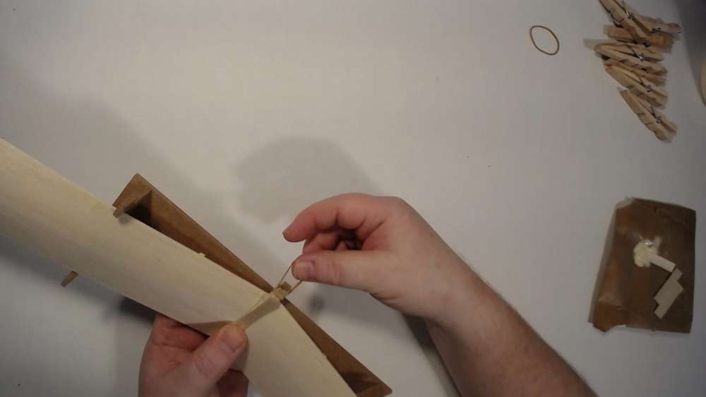
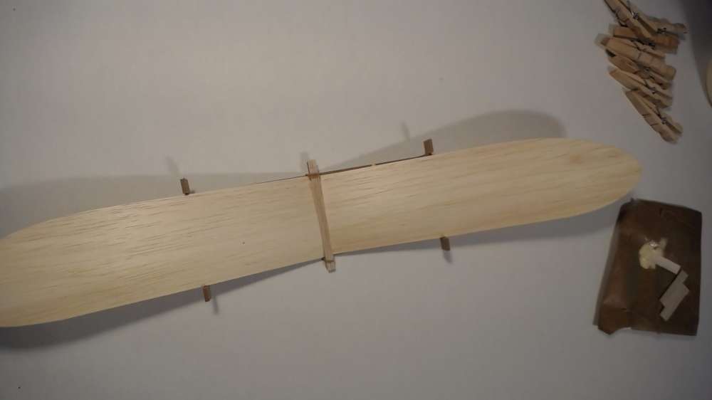
I drew a new wing mount in green (see below). It’s a nacelle-like piece that will glue on top of the wing seam. I included the angle of incidence in it so no wing shim should be needed. It can be strapped to the underside of the motor-stick (blue) using small elastics. You loop the elastic on the little post, pull it over the motor-stick then loop it back on the post. If the elastic is to long just go around an extra time.
I traced the wing rib (yellow). I then made a special rib for the wing root (red) that will snap into an assembly jig. The other four ribs will be like the stock yellow one.
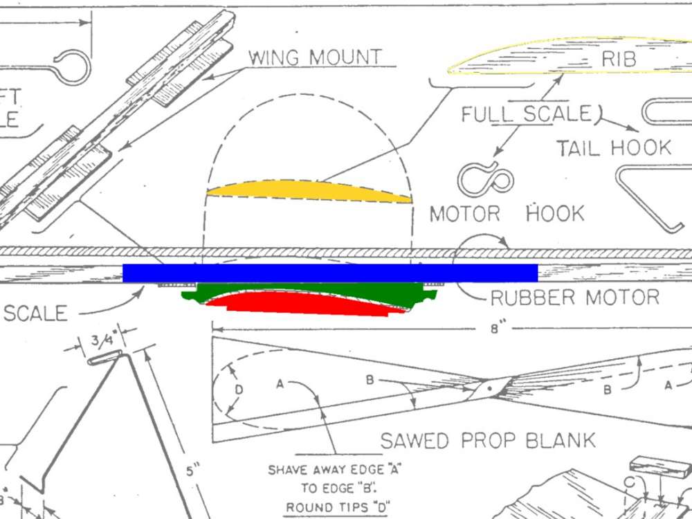
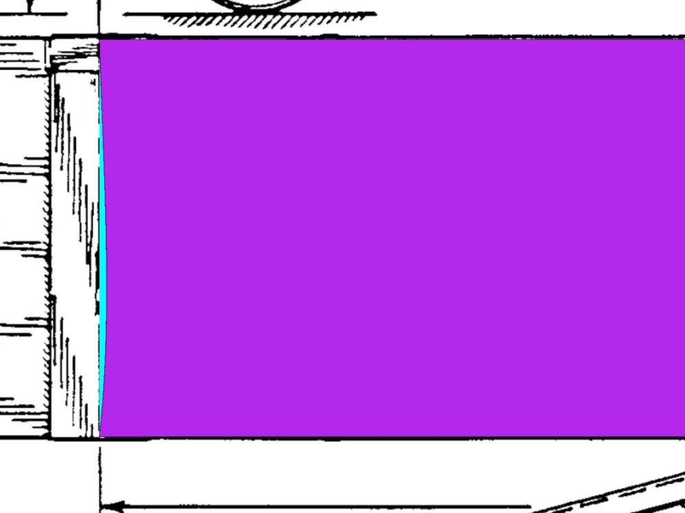
I then traced the wing. Notice the curve at the wing root. This is the required curve to allow the wing halves to join perfectly with the full six inches of dihedral. So the camber can come right to the root. I show a straight line in cyan so you can see the curve.
I used the wing as a template to create the fin and stab.
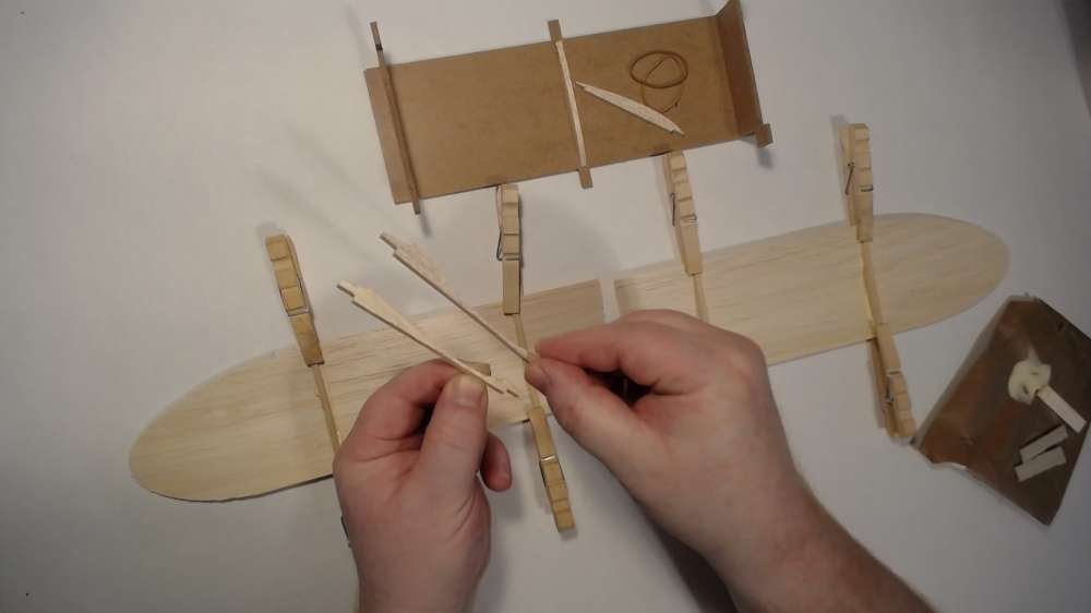
I then designed a jig for wing assembly. You can see the first jig I made below. I have a new version which is also a template for cutting out the parts without CNC. I’ll do a separate article on that.
The next step is called CAM (Computer Aided Manufacturing) using Carbide Create.
It takes drawings from Inkscape (or other sources) and creates the instructions for the CNC machine to cut out the parts. The instruction files are text containing G-Code. It contains X, Y and Z coordinates and instructions for the machine. In the CAM software you specify the diameter of the endmill (cutting bit). It will automatically offset from the work to make sure everything has the right measurements after cutting. Also the feeds and speeds are set up (how fast the cutting takes place, the spindle RPM and so forth).
Once the CAM files are created we’re ready for manufacturing (or actually cutting on the machine). Each machine will have it’s own software to load and run the G-Code files. I used OpenBuildsControl (which is a GRBL client). It runs on an Arduino which is open hardware but that’s a whole other story which is beyond the scope of this article.
So there are three layers of software, CAD, CAM and then Manufacturing (or Control).
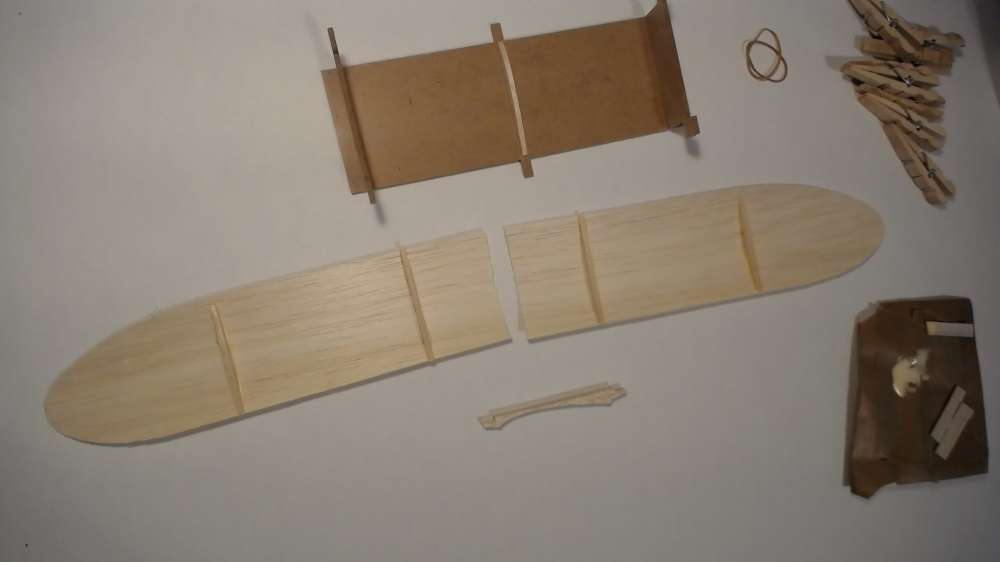
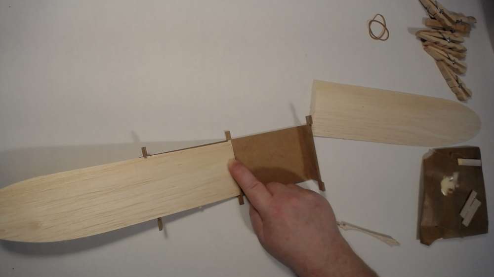
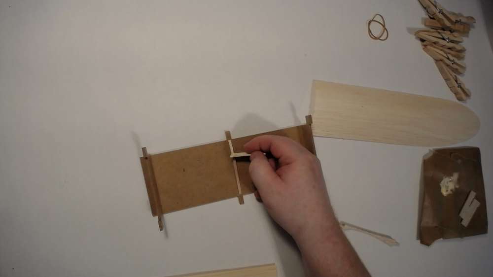
Here’s the wing assembly using the jig. I feel this is my biggest contribution to this redesign.
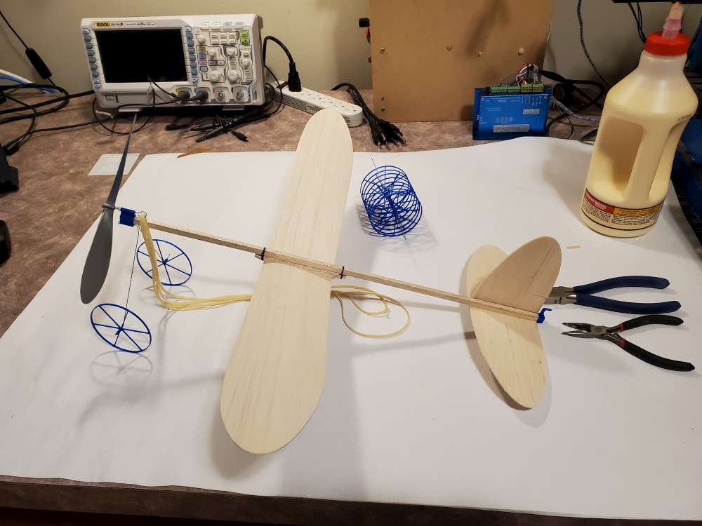
Next I designed the nose piece, rear motor hangar and wheels using Fusion 360. From there I 3D printed the parts using Cura and OctoPrint. There’s that three layer software toolchain again. CAD, CAM and Control.
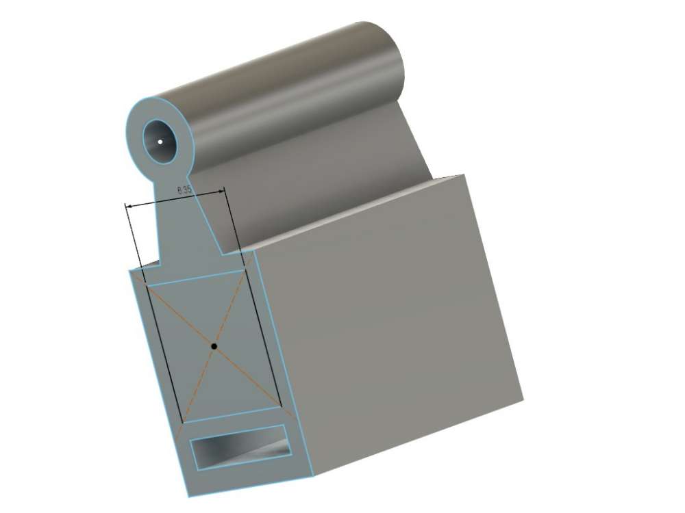
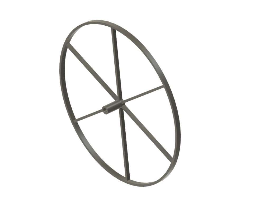
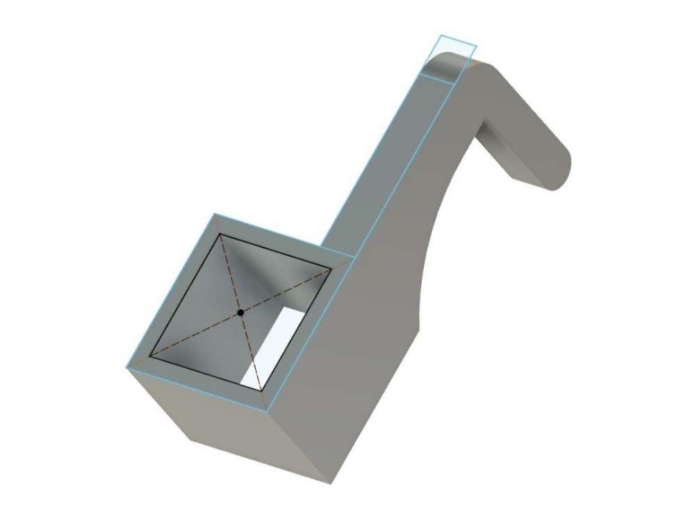
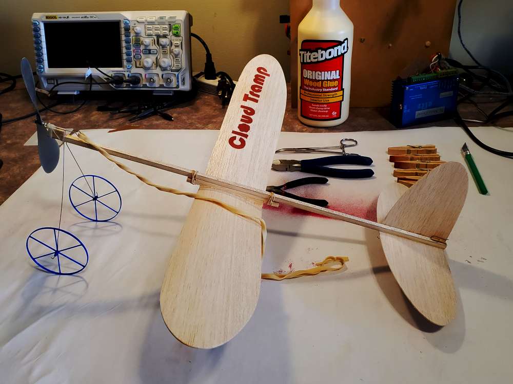
Here is the result.
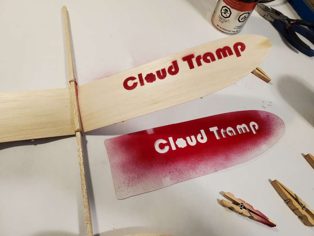
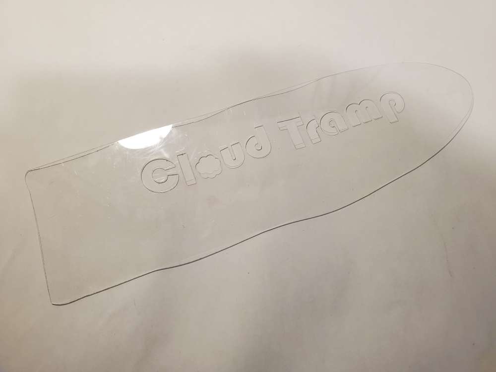
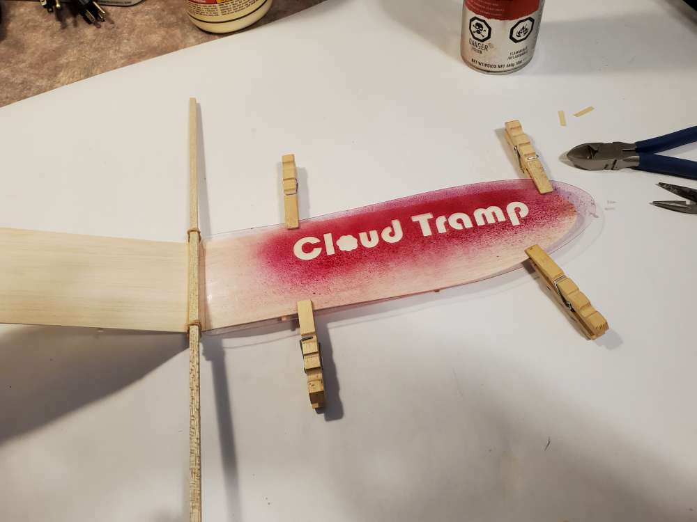
I then made up a stencil from polycarbonate sheet and put some light puffs of Krylon spray paint on it.
When Loren Dietrich and I started this bit of fun all those years ago, we never imagined that it would still be attracting interest now! But we did hope that it would fulfill Charlie Grant’s intention of encouraging youngsters to take an interest in aeromodelling and aviation in general when he designed the early prototype in the late 1920s. It’s very gratifying to see modern ideas and methods being applied to the construction of this ultra simple but very efficient design. If you haven’t read the very detailed description of the evolution of the Cloud Tramp in Grant’s book, it’s well worth seeking it out. I hope your efforts will help to boost the number of participants, particularly young ones, in GM 2021. I must credit Gary Hinze for taking over the organisation so willingly and successfully and to Volare products for their involvement. Best regards, Mike Parker (UK)