David Gee writes the “Safety Comes First” column for Model Aviation magazine, the publication of the Academy of Model Aeronautics. Sometimes for added interest he will include a mystery photo of an obscure aircraft or a view of an aircraft from an obscure point of view. Readers who correctly identify the aircraft are sent a digital file of a model airplane plan. A picture of the model is included in the article, so you know Dave has built and flown one.
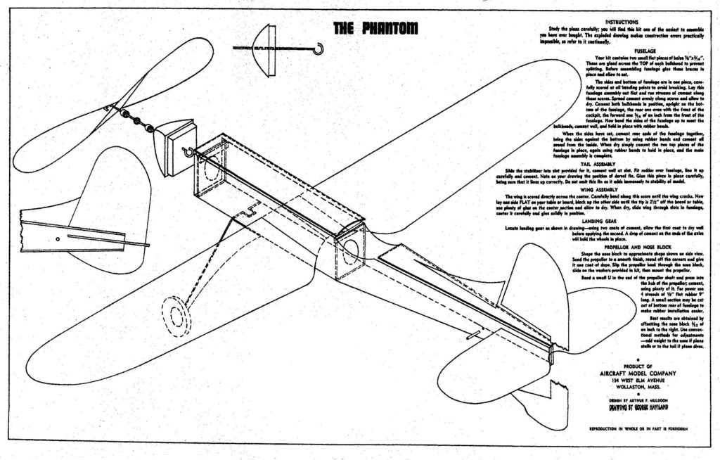
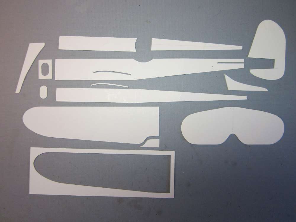
The model for the October 2017 safety column was the Phantom, designed by Arthur F. Muldoon and manufactured by Aircraft Model Company of Wollaston, Massachusetts. The undated plan shows an isometric drawing of an all sheet midwing monoplane with wood wheels and nonfreewheeling wood propeller. There was no building plan because all the parts were cut from sheet balsa and glued together according to the instructions on the plan. This indicates a pre-World War II vintage. The rest of Dave’s plan consisted of tracings of the sheet parts from Dave’s kit. One of Dave’s photos showed the flat sheet balsa parts on his cutting pad, which has 1″ squares printed on it. From that I was able to scale the wing span to 17 1/2″.
The plane looked like it had potential. The high aspect ratio wings are promising. The flat airfoil is not good. I decided to put camber in the wing. This includes cambering the wing slots in the fuselage sides. In early flight tests I found that the fin was too big, it produced a spiral dive. I reduced the fin and strake to 80% of the original size. Dave confirmed that he also reduced the fin size for the same reason. Sheet balsa construction is considerably heavier than stick and tissue. One advantage of heavy airplanes is they are less likely to get lost flying from small parks. It is always safer to fly in a large, open area. It flew quite well. Any kid would be pleased with it.
Plans and Patterns
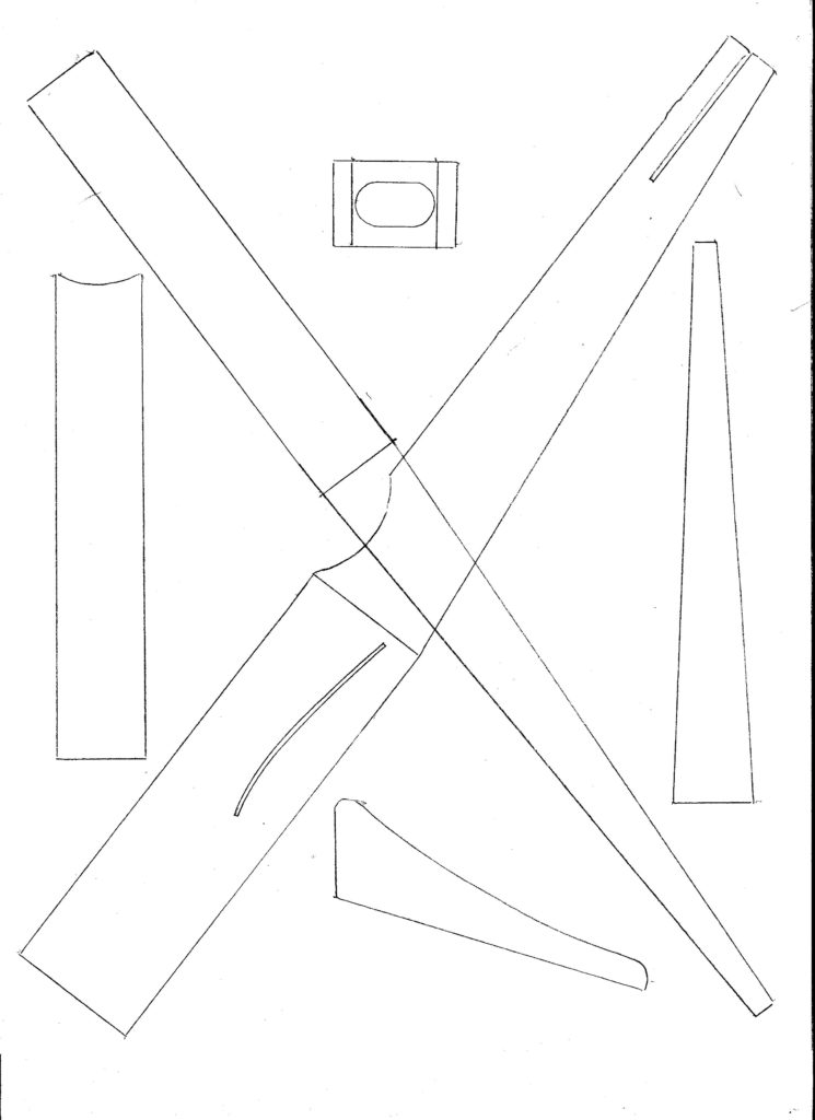
I started by scaling Dave’s tracings to get the 17 1/2″ flat wingspan when printed. I made a set of cardboard patterns from a cake box to guide the razor blade in cutting out the parts.
I traced these cardboard templates onto paper to make patterns you can use to make your own templates. Copy and save, print to a scale so that the wing half is 8 3/4″. Place them over a piece of cardboard from something like a cereal box and transfer the patterns by poking through the trace with a pin. Poke the holes just inside the pencil lines, pencil the outlines onto the cardboard and cut out with razor and scissors. These include the cambered wing slot, reduced fin and strake and a pattern for the 1/32″ landing gear wire. I modified the landing gear wire to fit into a slot under the fuselage, as will be explained later.

Building the Airplane
Sheet Parts
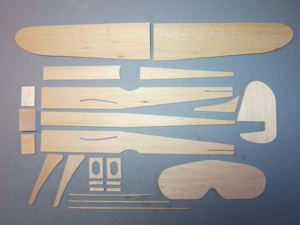
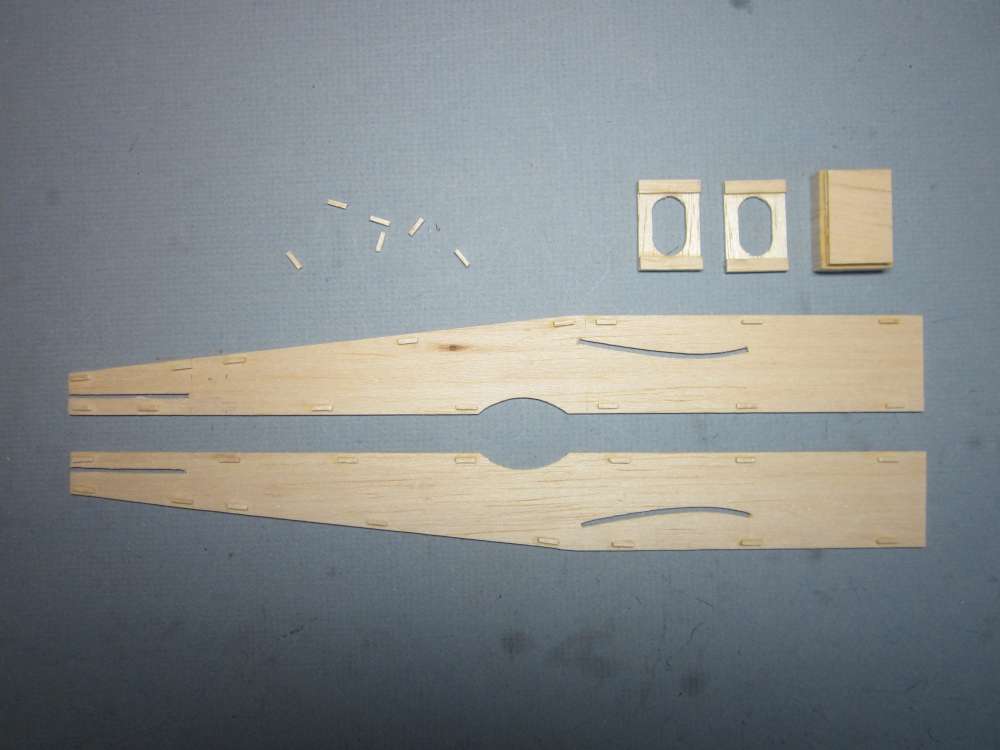
I cut the sheet parts from 1/16″ sheet balsa of 7# density. (A 1/16″ x 3″ x 36″ sheet of that density will weigh 12.4 grams.) I found 7# balsa to be adequate. This is not going to be an indoor duration plane, so no need to use the lightest wood. Using super light wood would require a correspondingly light prop. It already balances well without any ballast. Minor adjustments can be made with motor weight; a heavier (plastic) prop will probably require a heavier motor anyway.
You will make one of each except two of the wings, fuselage sides, bulkheads and landing gear fairings. You will need six of the 1/16″ x 1/4″ x 7/8″ plates, four to reinforce the bulkheads and two to form a slot for the landing gear wire. Those were added after initial test flights, as will be described later.
Nose Block
The part of the nose block that inserts into the fuselage is made from two pieces of cross laminated 1/16″ x 7/8″ x 1 1/4″ sheet balsa. The nose itself is a single 5/16″ thick 1″ x 1 3/8″ block with the grain running fore and aft. The prop shaft bearing is centered 1/2″ down from the top. The first bulkhead is 1/8″ back from the front of the fuselage, to allow room for the nose block insert. The top and bottom 1/16″ x 1/4″ x 7/8″ reinforcements are behind the bulkhead. The nose block can also be made from three layers of 1/8″, cross grained.
Landing Gear
I have redrawn the center of the 1/32″ landing gear wire into a 3/16″ tab that will insert into a slot between two 1/16″ x 1/4″ x 7/8″ balsa plates glued between the sides and against the bottom. You will need to cut the bottom sheet at a line 1 3/4″ back from the front edge and trim a 1/32″ strip off the back piece to clear the wire. This change will be shown later.
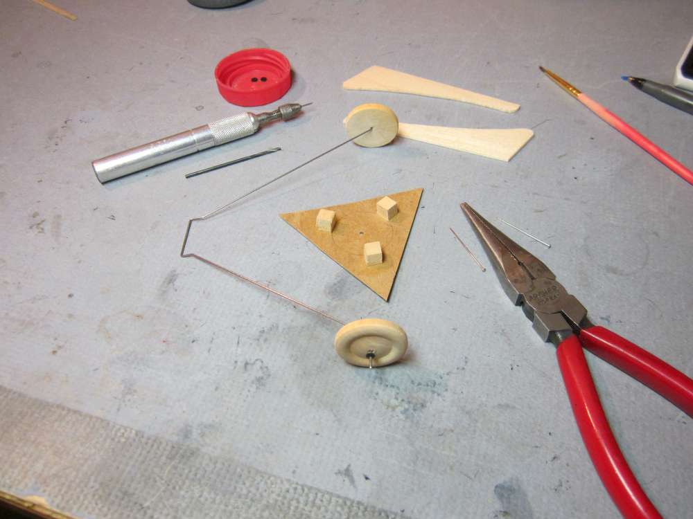
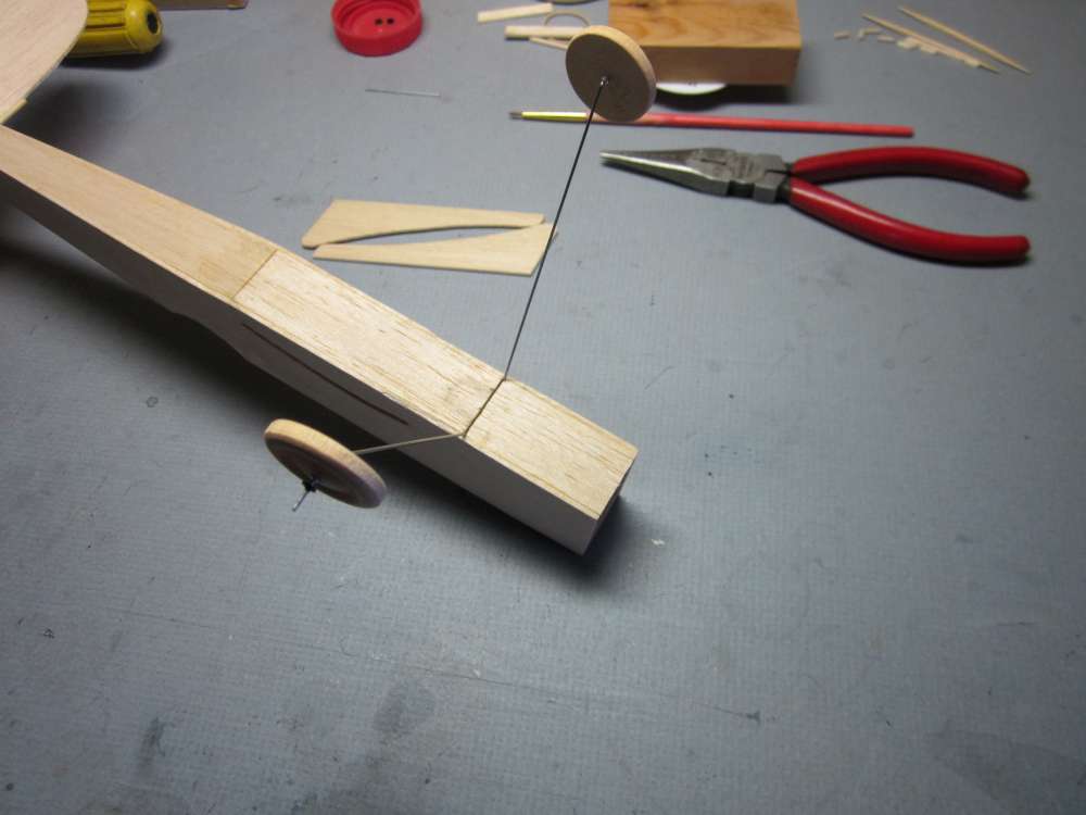
I wanted to use vintage hardwood wheels. The hardwood wheels are not drilled. I want the holes centered and perpendicular. I made this jig for the drill press.
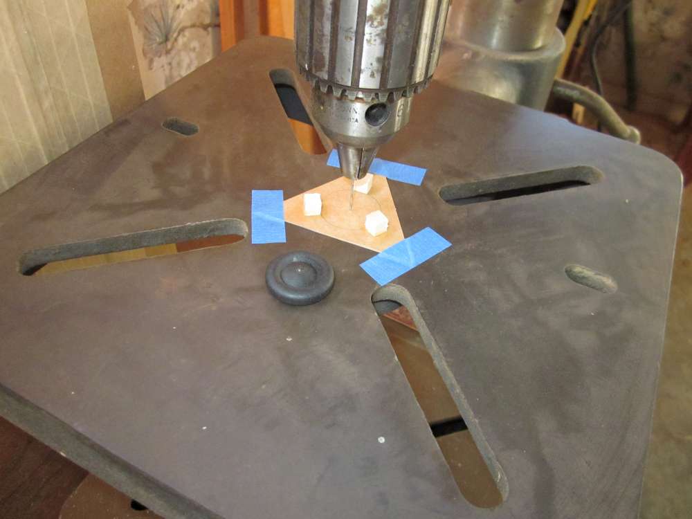
A 1″ diameter circle was drawn on heavy card with a compass. A 3″ circle was drawn around it, a hexagon inscribed and the equilateral triangle cut out. Small blocks were glued on tangent to the inside circle, 120 degrees apart. A pointed steel wire was put in chuck, lowered into the hole made by the compass and the triangle was taped down.
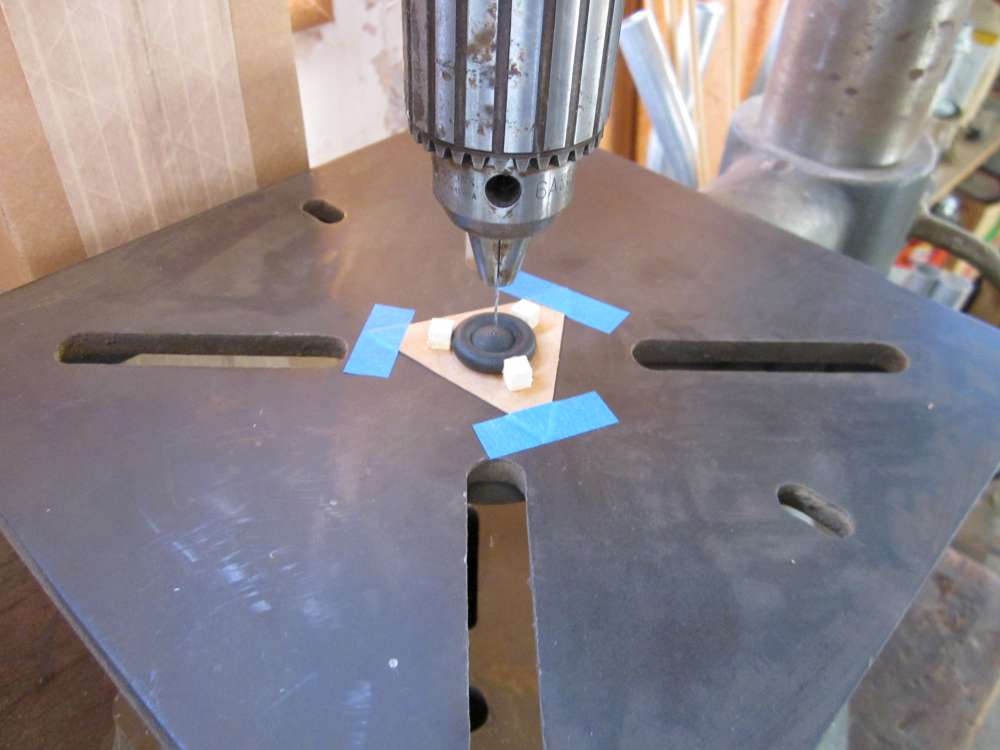
The wheel was put in the jig, the pin replaced with a drill and the hole was drilled. The wheel was held down with fingers while drilling. The drill went through the cardboard. Next time the jig is used, the drill will be used to center it on the table.
Two 1/16″ balsa disks glued together cross grain will make a fine wheel, with aluminum tube hubs. If you don’t have a drill press handy, you can use a hand drill guide.
You can also use two 1″ Peck wheels.
There is no tailskid. It drags on the bottom of the subfin. That can be reinforced with a heavy coat of glue, or a bit of thin wire.
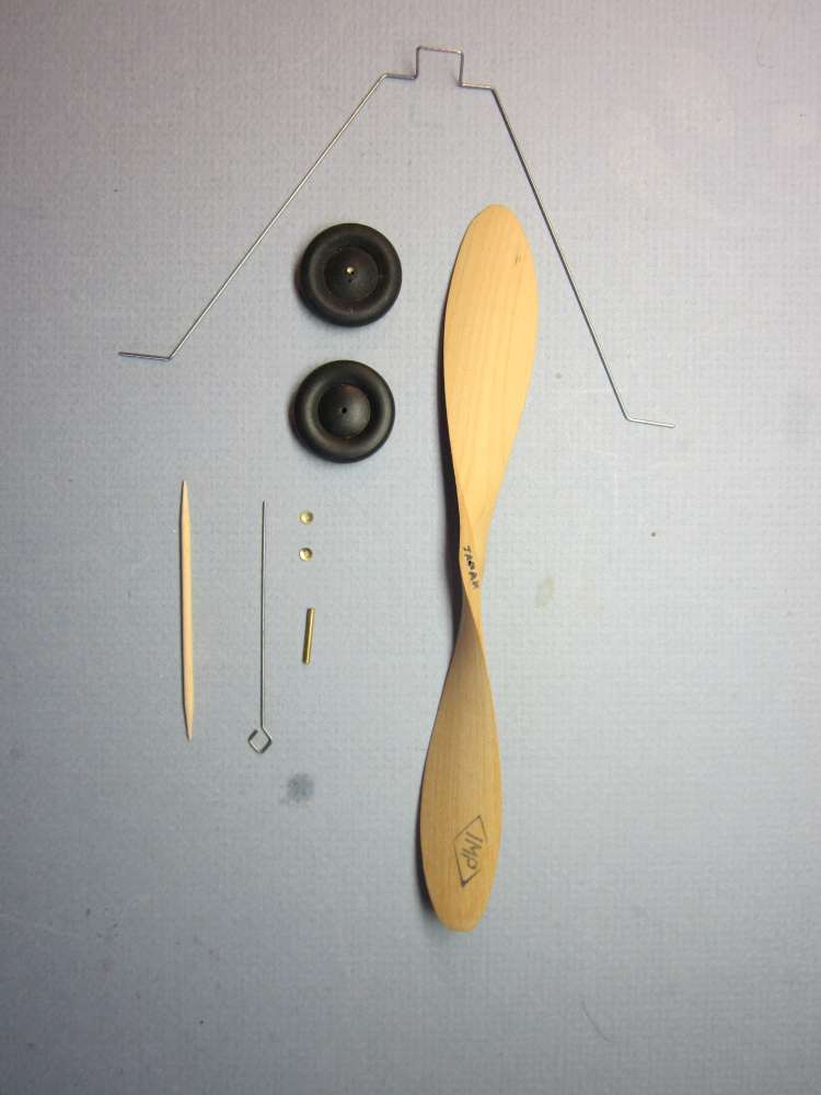
The original landing gear wire fit across the 1″ fuselage width and 3 1/2″ fairing, with 1/2″ axles. The center has a 3/8″ square brace that was glued to the underside of the fuselage. This picture also shows the paulowina prop, brass washers, brass tube bearing, Peck prop shaft and round toothpick rear motor peg.
Replacement Landing Gear
My Phantom went through a tree on its second outing. I got the plane back, but the landing gear is still out there somewhere with parts of the underside still attached. I went back several times to search without finding anything, even after the leaves fell from the tree. I used authentic period hardwood wheels. Not easy to replace, should have made balsa wheels for it. Probably should use a home made prop, too. I hate to lose irreplaceable things.
I decided to make a slot in the underside of the fuselage with sheet strips on either side inside the fuselage and have a rectangle of wire that slides up into the slot. The landing gear is located 1 3/4″ back from the front of the fuselage. It will be necessary to cut across the bottom plate and glue two 1/16″ x 1/4″ x 7/8″ plates across inside the fuselage to sandwich the landing gear wire. Since this is not evident from the original plan, I will describe it in more detail.
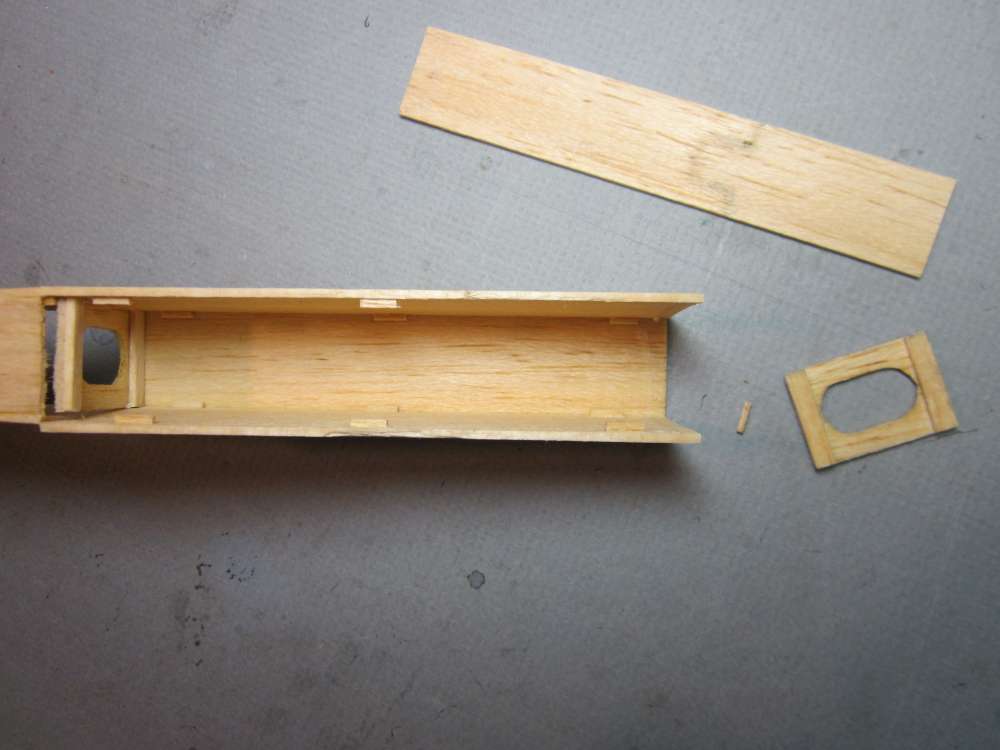
I soaked the bottom front in a tray of water to soften the glue and took the front bottom plate off. I scrubbed the old glue off, but you can still see the rust stain where the steel wire was originally glued. You can see the 1/4″ bits of 1/16″ square locator tabs. Two more are required to support the front part of the new bottom. This requires making two parts from the front bottom plate, 1/32″ shorter in total length than the original. The front part is 1 3/4″ long. It will also require two additional cross pieces to form the slot plates for the landing gear wire. A bit of 1/32″ sheet can go into the slot over the wire to fill the hole.

The nose bulkhead has been replaced and two location tabs added. The fuselage forward bottom plate has been cut in two and the landing gear slot plates have been made. The aft plate has been shortened 1/32″.
The aft bottom and slot plates have been glued in place. The slot plate is glued inside the bottom plate.
The forward slot plate has been glued in place, spaced from the aft plate with two pins. The slot plate is offset 1/16″ inside the edge of the side to provide clearance for the forward bottom plate.
The forward bottom plate is glued in place.
The new wire landing gear has been completed. New wheels have been drilled and bushed with 1/16″ aluminum tubing. The wheels are retained by 1/8″ plastic disks punched out of a HDPE carton lid with a leather punch. The end of the landing gear wire has been filed to remove any sharp points and also tapered slightly. A 1/32″ steel wire pin is forced through the center of each disk to make a pilot hole for the landing gear wire.
Another way to retain the wheels is to bend about 1/8″ of the end of the wire over at a right angle. There is enough wire to do that.
The instructions say that a drop of cement on the ends of the axles will hold the wheels in place. That has never worked for me. Even after building up several layers of glue, the wheel will jam on the blob of glue or the glue will come off the axle, the wheel with it.
The landing gear wire inserted into the slot. It is deliberately a tight fit. The wire still must be bent at the fuselage junction to conform with the angle of the fairings.
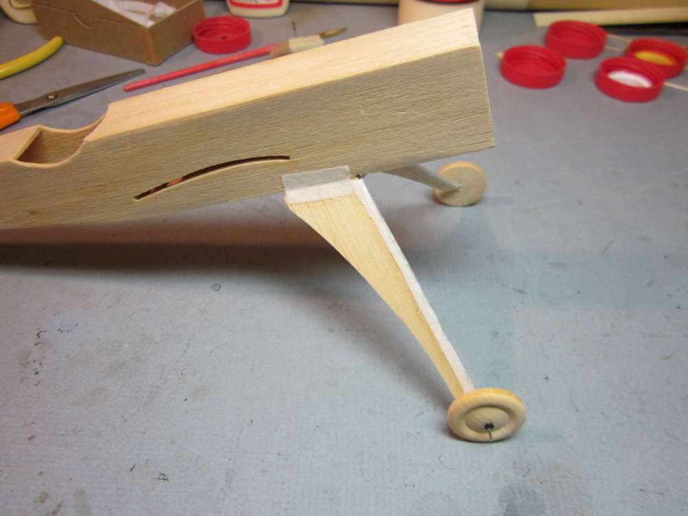
The completed landing gear. I used 1/4″ strips of thin cloth cut out of the back of an old dress shirt to reinforce the joints. Everything comes apart if there is not some reinforcement.
Here is the repaired plane with its new landing gear.
Propeller
By weighing the wing pattern and the rectangle from which it was cut, I was able to proportion the wing area to the area of the rectangle and found the total wing area to be 35.83 square inches. The rule of thumb for propeller diameter is that it should be a minimum of the square root of wing area, indicating a minimum prop diameter of 6″. Bigger is better. I checked the ground clearance with the landing gear and found that a 7″ prop would fit. I happened to have a 7″ paulownia wood prop of the same period imported by IMP from Japan, so I decided to use that.
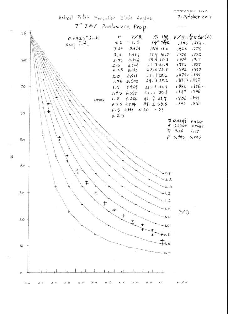
Here is the blade angle plot for the pre-war 7″ IMP JAPAN paulownia prop that I used on my Phantom. You can see that it is not perfectly helical, but it is much closer than most of the plastic props I have tested. P/D runs around 0.8 to 0.9, low for duration, good for rapid acceleration. They worked in their time and may have been right for the heavier model construction practices of that time. Those heavier models would have required more power and faster rpms. This one worked OK for the Phantom. I was not expecting a duration flyer from sheet balsa construction. But I was satisfied with the flights. Flights fit well in a small city park.
This tells me that I should probably find some paulownia wood and start carving my own props. Not that it matters if we waste 75% of the energy from the motor, rubber is cheap and I lose enough planes out of small parks already.
Paulownia props are very hard to find these days. I suggest getting a 7″ balsa prop blank from George Bredehoft. Dense balsa would be a good approximation to paulownia. These have a P/D of 1.3 and you can choose your own blade pattern. (A wider prop blade with higher P/D might affect the longitudinal area balance and favor going back to the larger fin.)
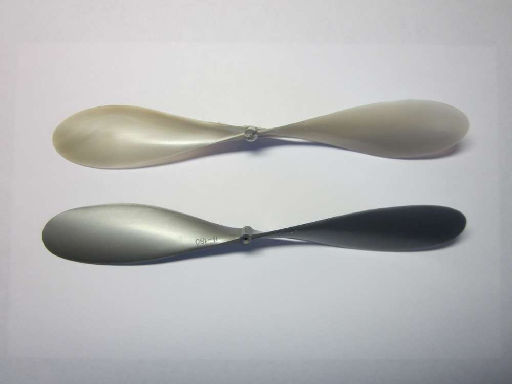
Peck makes a 7″ plastic prop. They weigh 4 grams each. They are opaque silver, marked JAPAN, U-180. Peck props typically increase in pitch toward the tip and have P/D values around 0.7 to 1.1 with average around high 0.9s. A plastic prop might be too heavy, even if scraped. You might need a heavier motor, though, so the balance might be OK.
I have some other 7″ translucent grey plastic props that weigh 2.96 grams each. They are marked with a six pointed star inside a hexagon and numeral 18. I don’t remember where I got them.
Cutting an 8″ Peck prop down to 7″ will increase the average P/D from 0.98 to 1.09, but cutting down a Peck prop makes it heavier for the diameter, the hub area is proportionately thicker.
A 7″ paulownia prop weighs 2.2 grams, same as a 6″ Peck prop. That might be a worthwhile option to try.
Fuselage
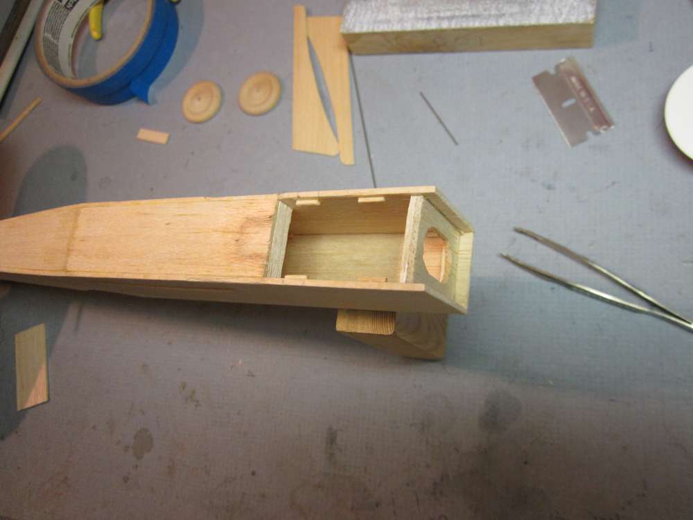
I used 1/4″ bits of 1/16″ square, set 1/16″inside the edges of the fuselage sides, to locate the top and bottom plates between the sides. I used a spacer jig to locate them the correct distance in from the edges. You can also see the completed fuselage formers and nose block. The formers are glued in place first, at right angles to one of the sides, then the other side is glued on. Next the top plates are glued between the sides and to the formers. Finally the bottom plates are glued on.
You have already seen how I later modified the underside of the fuselage to accept new landing gear into a slot in the bottom. You must incorporate those changes into the assembly of the bottom plates to the sides. Work from the tail end forward.
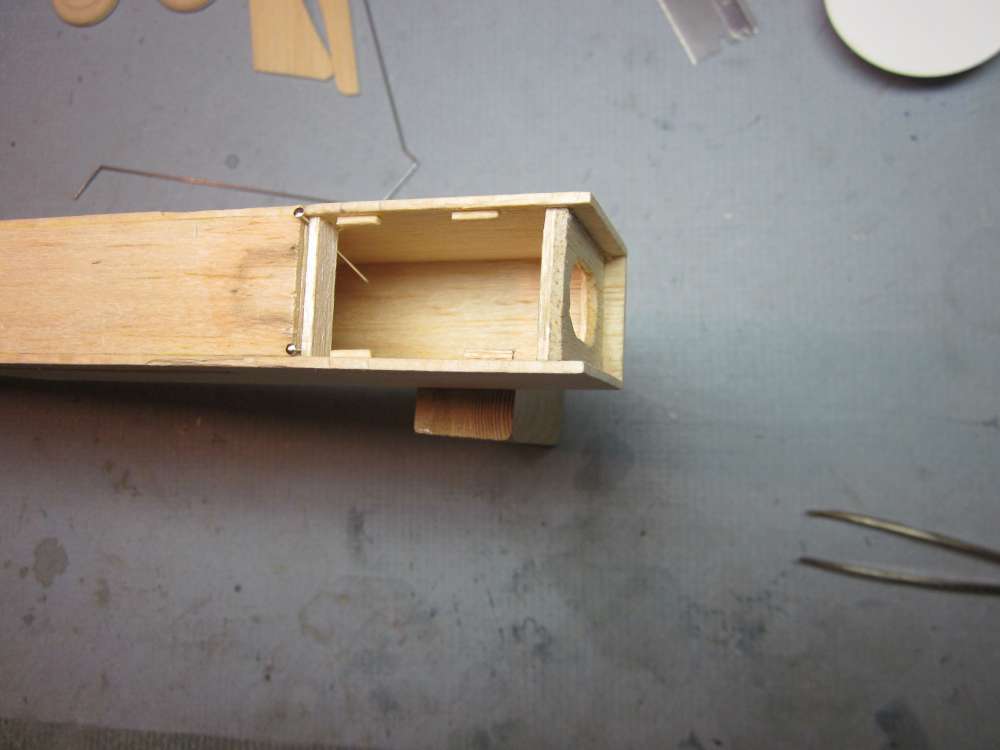
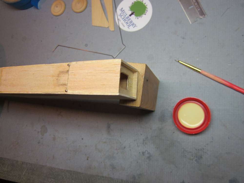
I also added a 1/2″ opening in the bottom of the fuselage to observe the motor peg being inserted into the rubber motor .
Wing
I made a paper pattern for the wing and folded it in half to make a symmetrical half pattern in thin card stock. I used Sig cambered wing boards to wet form camber into the wings. I traced the camber onto the slot location in the fuselage pattern and cut a cambered slot 1/16″ wide.
The wing is soaked until it is saturated and pliable, for soft wood this might take only a few minutes. Blotted dry, it is placed on the Sig airfoil form (SigB112), lined up and wrapped with an Ace bandage, dried overnight.
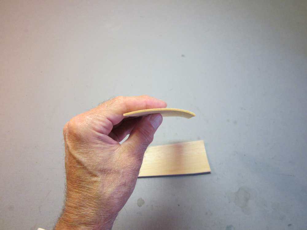
Formed in this way, the wing will hold its camber without ribs.
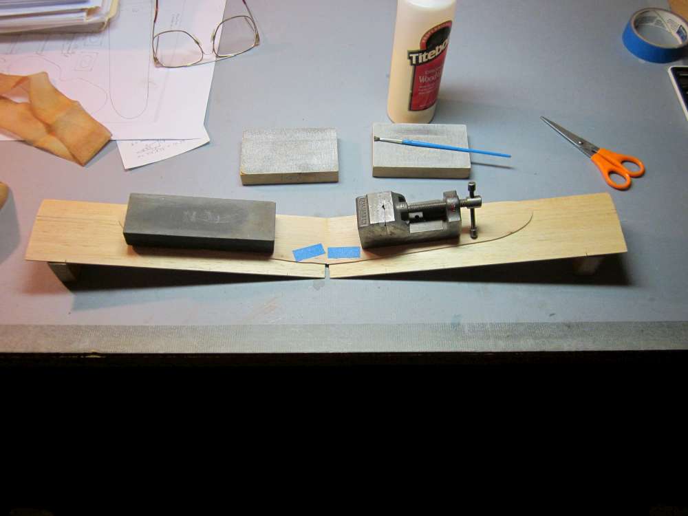
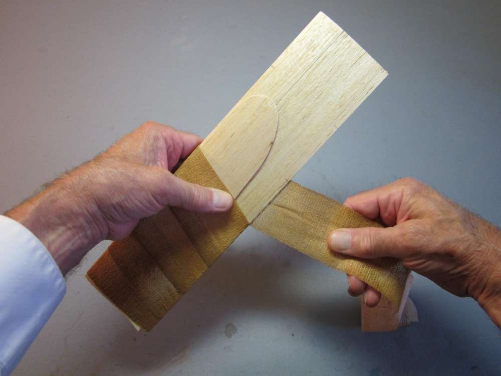
To form the dihedral gore, I made the center section full 2 3/8″ chord all the way across. Each wing half is placed on the form board which is blocked up to the proper dihedral angle and then the root is sanded to the proper bevel, removing wood from the arc, but none from the leading and trailing edges. The sanding block is squared so the sandpaper is perpendicular to the surface of the table when the edge of the block is flat on the surface. The sanded root ends are preglued and after the first coat is tacky, more glue is applied and everything is stuck together. The trailing edge cutout is left in place until after the glue has dried, then it is cut out.
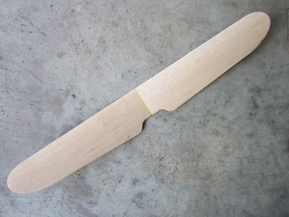
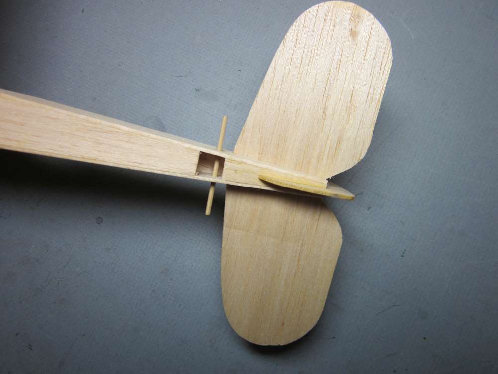
I put pencil marks on the wing leading and trailing edges to help align the wings with the fuselage sides. The wing can be taken out for easier transport and storage, although you can glue it in place if you like. It does get knocked about and often has to be reset after a flight.
Rubber Motor
The plan says to use four strands of 1/8″ flat rubber, 9″ long. Rubber came in different thicknesses in those days, often 1/30″ = 0.033″, compared with the modern standard of 0.042″. Also, modern rubber is believed to be better at storing energy than 1930s rubber. The distance between the prop hook and the motor peg is 9 3/8″, so a 9″ motor isn’t long enough. I prefer to use a motor about twice the available distance. Longer than that is difficult to manage. The cross section of the motor determines its torque. The required torque is determined by some aerodynamic characteristics of the plane and its weight. The original build came in at 21.4 grams. The empty CG was at 0.85″ from the leading edge. This is a high aspect ratio, cambered wing with a slender fuselage enclosing the motor. I estimated that two strands of 1/8″ would be adequate for initial flight testing. So the motor will be an 18 3/4″ loop of 1/8″ Tan Super Sport rubber strip. The knot will go in the back at the motor peg and there will be a 1/8″ O-ring at the front end to ease winding the motor and transferring it to the prop hook. This motor can take an estimated 1,946 maximum number of turns when lubed and stretch wound slowly. With the motor installed, the plane weighed 24.4 grams.
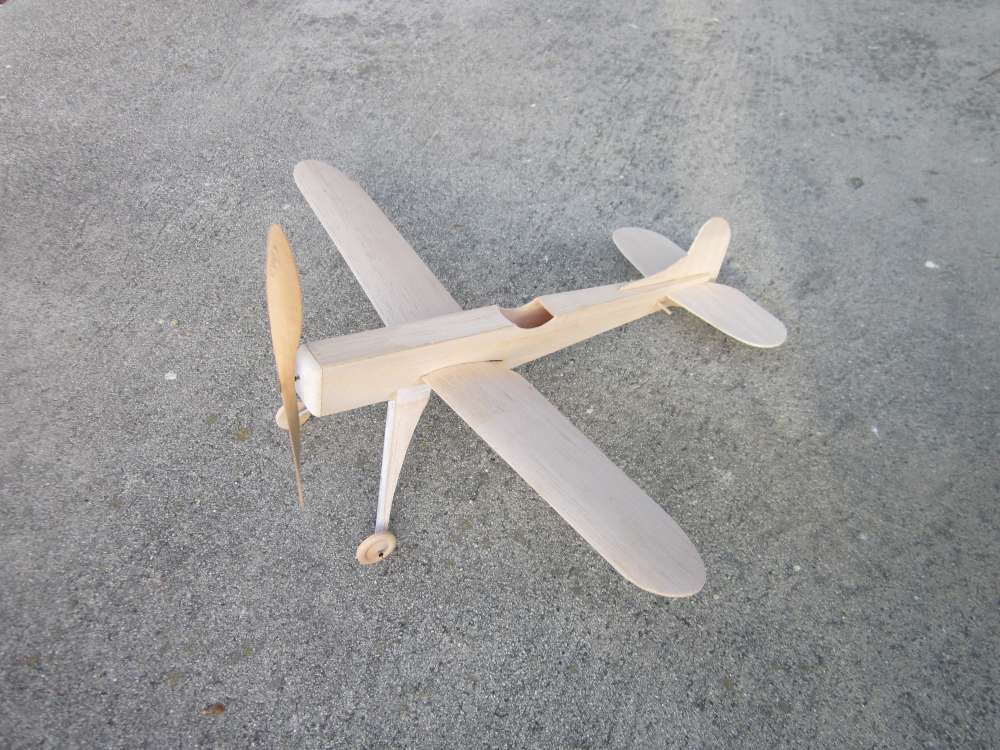
The Finished Airplane
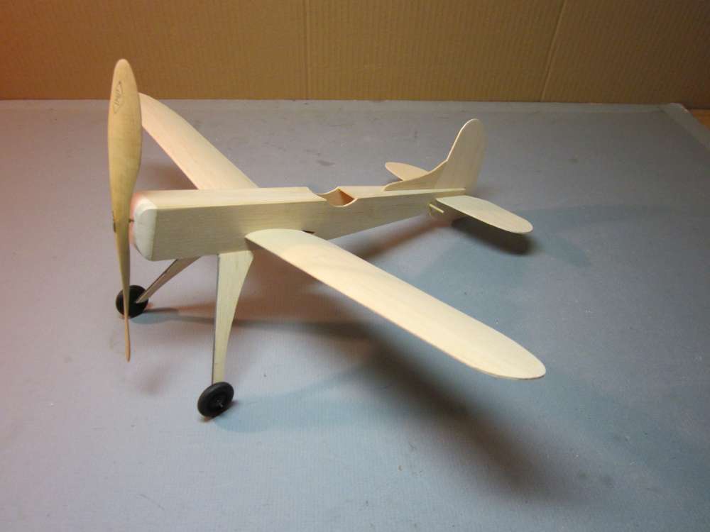
The Phantom could be colored with felt pens. That should probably be sprayed with clear Krylon or other fixative to keep the colors from running when you land on damp grass. I prefer the Plane Jane factory finish.
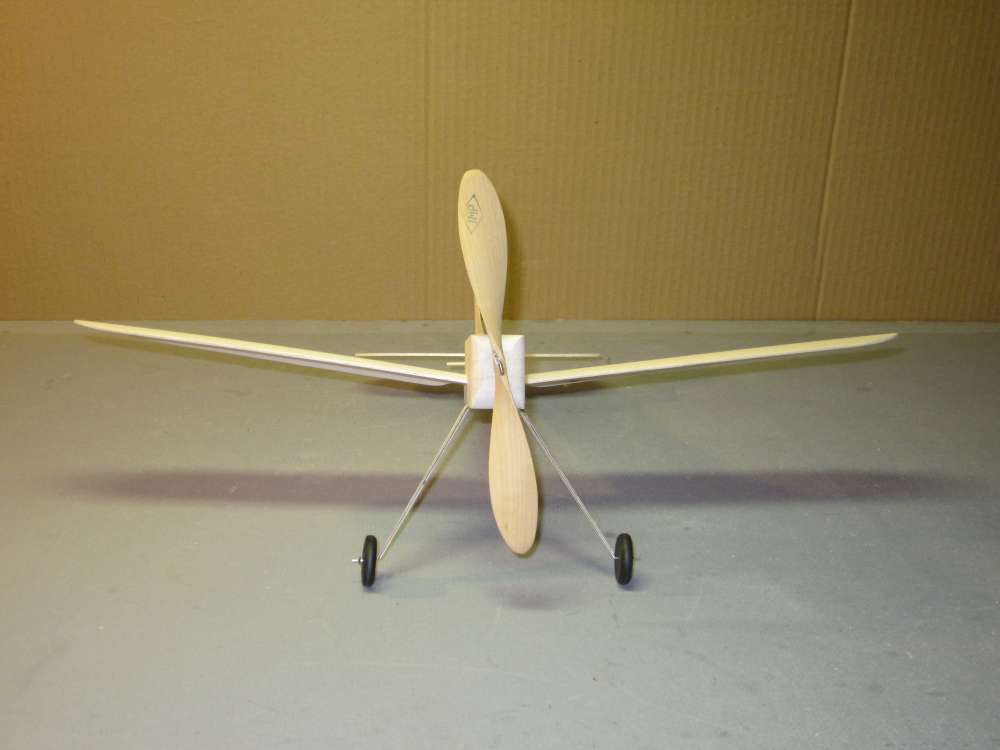

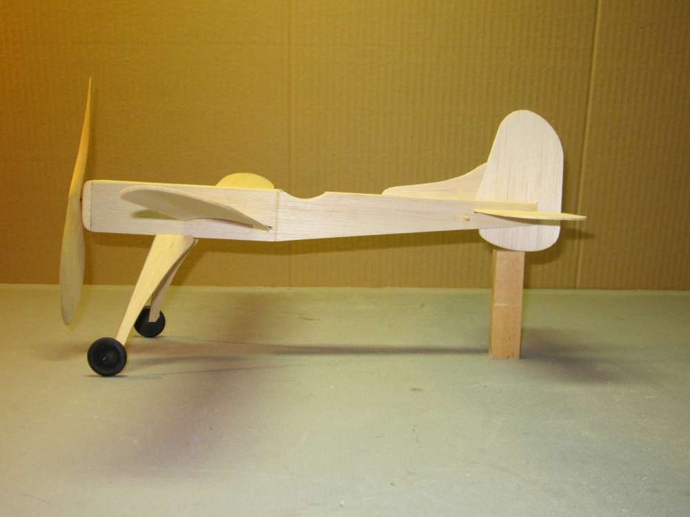
Pretty sleek, looks like a racer. But what’s with that huge fin? We will find out in flight testing.
Flying the Phantom
Winding the Motor
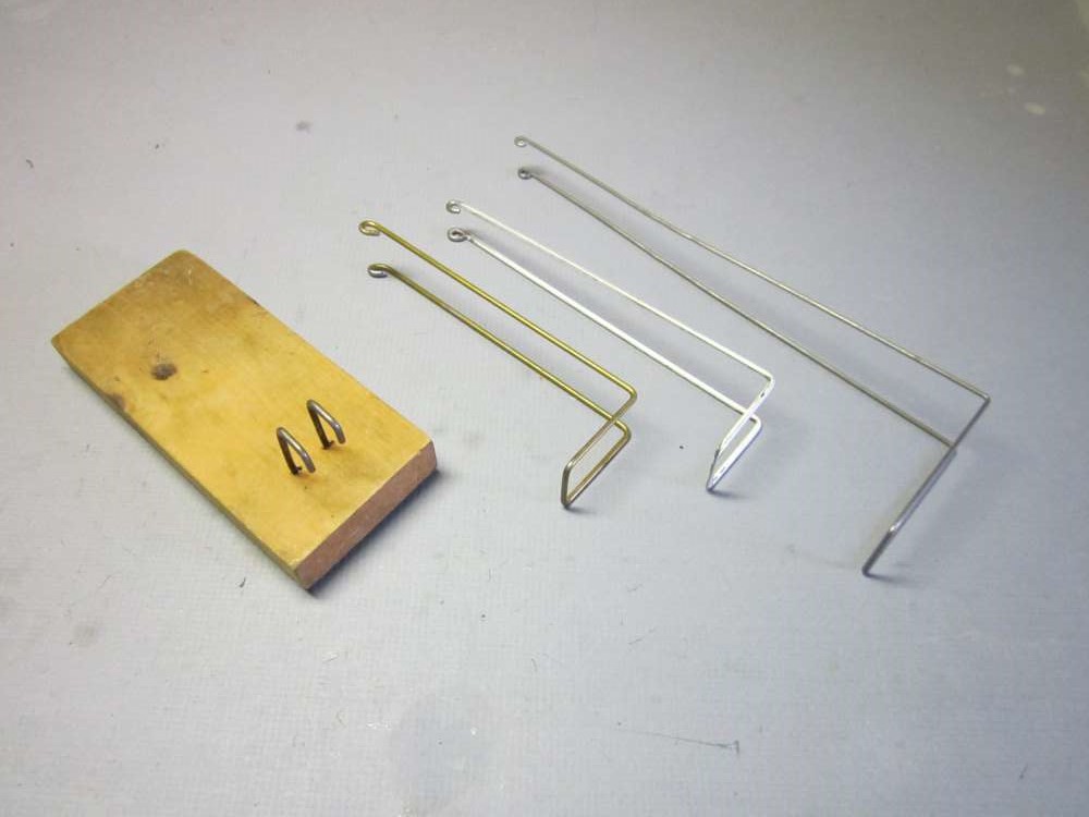
When I go flying by myself it is necessary to have some way to hold the back end of the rubber motor while I am applying turns to the front end with a winder. It is also helpful to be able to stretch the motor to keep the knots from rubbing on each other and get more turns into the motor. On this airplane, the motor is wound from the front and some way is needed to hold the motor peg at the back. The foot stooges made from coat hanger wire do the job. Make one that is long enough to clear the tail with plenty of room for your foot to hold it down.
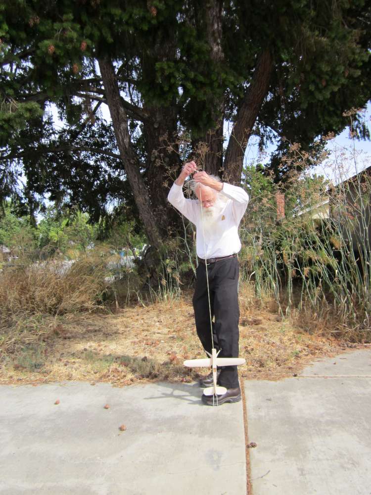
Note that the fin is away from the foot and the prop is in the shirt pocket. With the motor stretched, it is important to keep a secure grip on that stooge with the foot!
First Flights
Monday, 9. October 2017, Houge Park. Clear, sunny sky with smoke. First flight. 9 3/8″ space for motor, make it 2X, equals 18 3/4″. Calculation said two strands of 1/8″. 1,946 breaking turns. Start with 1,200 turns. Had a little trouble getting the O-ring on the hook, should have checked that at home. Nice launch, straightaway and level, but tight left turn, steep left bank, sideslip into ground, cartwheel. Put 1/16″ grass stem under left side of noseblock, did the same to right. Maybe it needs more dihedral. Took shim out, took it over to water fountain, wet rudder and bent right rudder. Blotted it dry. Hot dry air. Similar right turn. Reduced rudder quite a bit, back to left, not as much bank, but still tight circle. Wings more or less level, but descending. Time to rewind the motor. Sat down to make notes in log. Got up and started preparing to rewind motor and felt wind on face, too much for test flying, so I went home. Opened motor hook to clear O-ring. Fixed cracks in fuselage side near wing slots. Made a labeled can to store motor. Soaked wing apart and put back in form so I can resand dihedral gores. By the time everything dries, the wind may have died down and we can try again. CG with motor is 1.25″, 62.5%. Total weight with motor is 24.4 grams.
Spiral dive on flight test, reduced fin to 80%. Weight reduced from 21.2 to 20.9 grams. Plus 3.2 gram motor. Empty CG moved forward by 0.1″ to 0.75″.
Too windy on Tuesday. Windy most of Wednesday. I went over to the park at 6:30 PM after the wind had subsided to a few leaves fluttering in the tops of the trees, not noticeable on the ground.
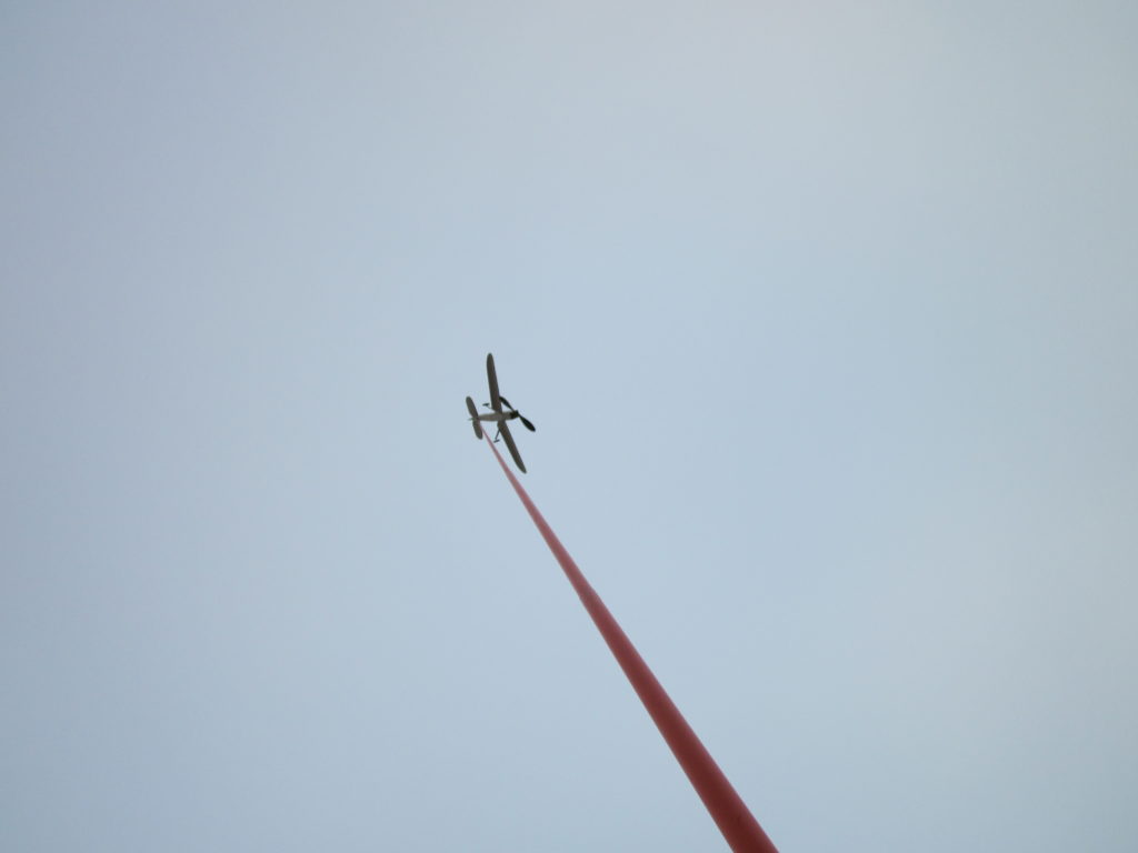
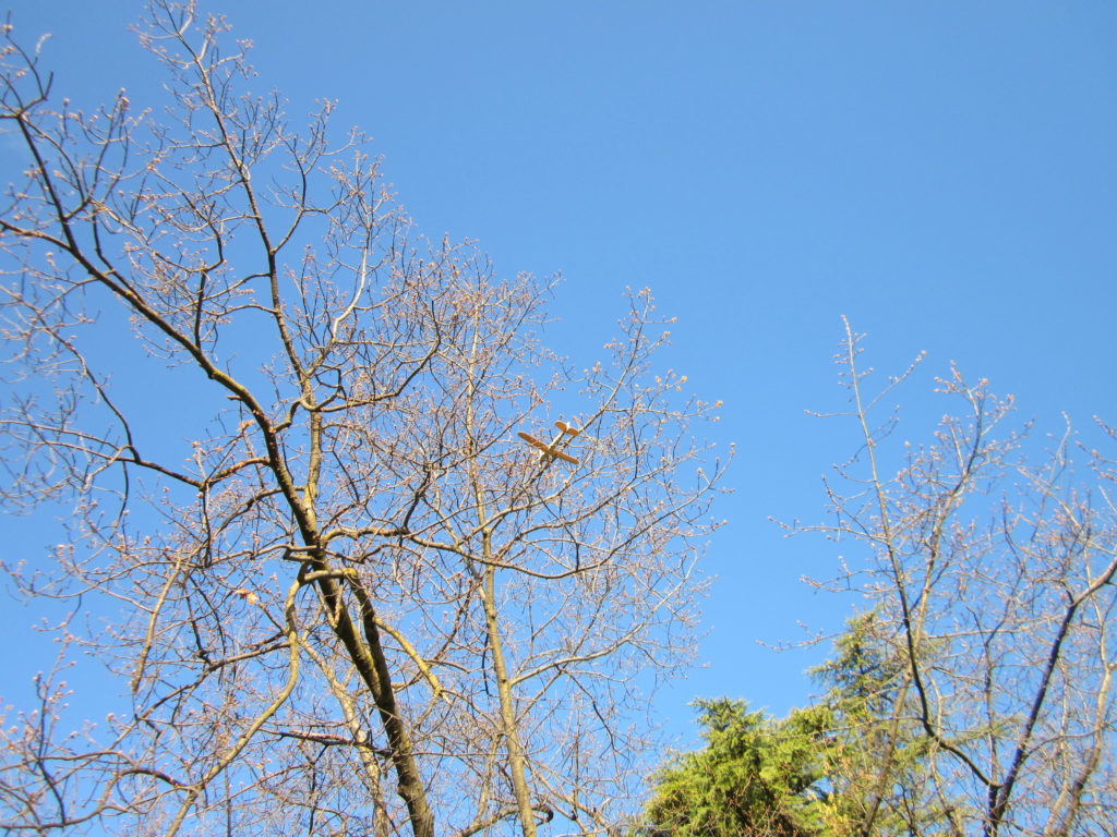
Wednesday 11. October, 2020, Houge Park. 6:30-6:45 PM, right after sunset, smoke in the air, slight flutter of leaves in the treetops. 1,200 turns, flew straight away, climbing slightly with left wing about level, yawed left, slight phugoid. Went straight across lawn into tree on other side, about 15′ up from the ground. I got it down with the pole. Both landing gear struts cracked from fuselage, left one separated from wire. Second launch, similar, descended to ground. Cracked balsa fuselage edges so landing gear struts came loose. I looked at wings from front, they seemed to be symmetrical, but looking at end showed more camber in left wingtip. Fin centered. Back home at 7:00 PM. Reglued landing gear struts. Soaked wings and put them back on forms.
Tuesday 17. October, 2020. Houge Park, soccer game in center of field. 1,200 turns, expected it to circle left, launched with right shoulder to soccer game, it turned right and flew two circuits over the game, but landed safely. Second flight, 1,300 turns, flew straight, then turned right behind trees at the edge of the field, and hit tree on other side of sidewalk. Found plane on ground, but couldn’t find landing gear, it got too dark to see.
Later Flights
In February 2020 a discussion of paulownia props prompted me to post a picture of my Phantom as an example of a plane with a paulownia prop. That led me to getting the plane out of its storage box and making the repairs to the landing gear noted above. The empty plane now weighs 20.6 grams. A couple short tests with 100 turns seems to show good trim. It has been too windy lately for flying.
Wednesday morning, 5 March 2020, there was no wind at Butcher Park. I started with 1,200 turns (61.66%) in an 18 3/4″ loop of 1/8″, it turned right into a tree, about 15′ up. Got it down by putting the end of the retrieval pole into the motor viewing window in the back of the fuselage and lifting it up. Launched the other direction, it made a long right arc into a tree on the far end of the field, again about 15′ up, got down in the same way. Licked the left side of the rudder, bent about 1/16″ right rudder, three right circuits, tightening at end, 41.37 seconds. Reduced rudder to 1/32″, 1 3/4 circuits, 42.99 seconds. 1,300 turns (66.80%) straight to tree line, turned right at the last seconds, circled baseball diamond, 45.93 seconds. 1,400 turns (71.94%), straight down field into tree, fell to ground. Found that the tailplane and fuselage side were cracked, need to be repaired. I think the wing is sliding around, too, I left it a sliding fit in the wing slots, think it should be tack glued to get reliable flights. It wants to go straight with more turns, needs right thrust for right circle at high torque, less right rudder then for descent. It will need a little more trimming before I will be able to give it a full tank.
In my last report I told how the Phantom would fly straight into the trees at the end of the field when the turns count got to 1,300. The increasing left torque is balancing the 1/32″ right rudder. I glued a 1/32″ balsa strip to the left front of the fuselage to give the nose block 1.79 degrees of right thrust.
18 3/4″ of 1/8″, estimated 1,946 breaking turns. 20.8 grams empty weight.
The weather forecast said 1 mph wind for this morning through noon, slight chance of rain towards noon. When I arrived at the field at 7:39 AM there was a flock of geese and the sprinklers were going along the opposite edge. The lawn was wet and there were puddles in the center. I decided to fly anyway. I started with the same number of turns as the previous session to gauge the effect of the right thrust. I counted the number of circles flown to the nearest 1/8 circle. Flight time in seconds.
1,200 (62%) 1 5/8 43.67 Large, consistent circle, not high. 1,300 (67%) 1 1/2 44.27 Good circle. 1,400 (72%) 1 3/4 53.03 Motor came off prop before landing, completely unwound. 1,500 (77%) 1/2 ~29 loud rap, steep stall, spin and dive, no motor visible in cockpit, prop separated from plane, no motor or O-ring on hook. I pulled the motor out by the tag ends through the opening in the bottom of the fuselage and it was unbroken. The O-ring had come off the prop hook. I am using a Peck square prop shaft hook. Should have bent up a right handed overlapping pigtail. I freshened the lube. 1,500 (77%) 1 3/4 55.69 Larger circle, higher up. Getting close to a minute. 1,600 (82%) O-ring got away from me, lost quite a few turns, launched anyway. The shim had come loose, I lost the stooge and by the time I found it again there was enough wind to make leaves flutter.
Left the field at 8:49 AM. Four good flights in an hour of flying. The right thrust seems to be about right. We’ll see next time if the circle opens up too much with more torque.
Thursday, 12 March, 2020. Weather forecast said low wind, no rain for the morning. I arrived at 7:46 AM, cool, overcast, still. Only a couple geese on the field.
1,600 turns (82%), 1 5/8 laps, 50.50 seconds, full row of knots left.
1,650, (85%), 1 7/8, 46.83 ending in tree about 12.85′ up.
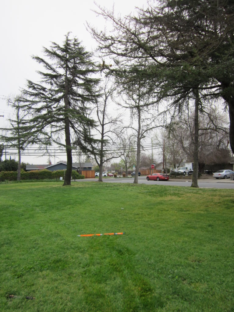
The pole is 45 1/2″ long, placed directly under the plane, perpendicular to the line of sight, allows estimation of height.
Again I was able to lift it straight up by putting the tip of the pole into the peg viewing hole.
1,650, (85%), 2 3/8, 1:02.25. A few twists left in the motor. Achieved my goal of breaking a minute. Paced circle diameter at 28 paces, 30 paces in 100′ makes it 93 1/3 foot diameter, 293.22′ circumference.
This allows us to calculate some performance parameters. 2 3/8 x 293.22′ = 696.38′ over the ground in 62.25 seconds is v = 11.19 fps = 7.63 mph. 1,650 revolutions in 62.25 seconds is n = 26.51 rps. Prop diameter is d = 7″ = 0.583′, nd = 15.46, advance ratio v/nd = 0.72. I will be looking at the blade angle graph for this prop to see what kind of attack angles we are getting.
I wanted to get a video of it flying for a minute. I put in 1,650 turns, got out the camera and turned it on, fiddled everything around until I got in launch position and “Launch!” Crack, bang, thud. I think the landing gear hit the camera and it dove right into the ground, nose down, stopping the prop. The angled collision with the ground knocked the wing loose. I put it back in place, handwound 30 turns into the motor, set up and got off a great launch. Steep steady climb, higher than I had ever seen it before, circled 2 3/4 times. Heard the motor rattle, backwind the motor (fixed prop) and pitch down into a steep descent. No time, no watch, I will time it on the video when I get home. Light breeze on face, leaves fluttering, to risky for another flight, not a good idea to fly a broken plane, so I went home at 8:46 AM.
At home, downloaded the camera, no video! No idea what happened. I could swear that I heard the camera beep when I started and beep when it ended. These digital cameras have sensitive microswitches all over them, so it is hard to finagle them into position while holding a fully wound model without brushing a knuckle over one of the buttons and upsetting everything.
I glued the wing back and am ready for the next low wind, no rain opportunity to fly.
Propeller Performance Analysis
Blade angle beta is the angle between the blade chord and the plane of rotation. Measured with my prop gauge.
Advance angle gamma is the angle that the blade element makes going through the air. Gamma is a helical curve by definition, in this case corresponding to a P/D of 0.7235.
Attack angle alpha is the angle at which the blade chord meets the oncoming air, equal to the difference between beta and gamma.
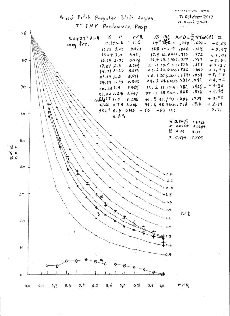
The blade attack angle should correspond to the attack angle of maximum L/D. We have very little good data for our little prop airfoils at our Reynolds numbers. What I have, and what I find for good performing props, is an angle around 4 to 6 degrees. So this one is performing well from about 1/3 to 1/2 of its radius. This is actually better than most plastic props which have a linear blade angle distribution. This prop fairly matches a helical distribution. It would be better if it had 5 degrees over the outer portion of the blade where most of the work is done. A higher blade angle in the outer half would likely significantly improve its performance. At least there is no place on this prop that is at a negative attack angle, which is common on plastic props.
Thursday, 19 March, 2020. About 8 AM. Butcher Park. Clear, sunny, still, wet grass, one dog running around. This is the day for getting a video of a one minute flight. No stopwatch, times will be taken from the videos later. All flights with 1,650 turns.
First flight, into tree at 37.54 seconds.
It was 25 feet up, easily recovered with the pole.
Second flight, bad launch, recovered just above ground, climbed just over head height, 34.85 seconds. It must be given a smooth launch, released at flying speed with a right bank.
Third flight, good launch, not as high as some, 1:00.55 time. Wind drift took it uncomfortably close to downwind trees. It might like a bit more right thrust; first few seconds it goes straight, even with right bank at launch. Wind moving leaves and small branches, time to go home at 8:46 AM.
Here is the video. Note the abrupt change in the descent right at the end. This is due to the motor running out of turns, the prop backwinding the motor and coming to a stop. This is a fixed prop, no freewheeler. This means the motor could be thinner and longer to get longer flights.
I bought a kit of the Mystery Phanom and it went together very nicely, including forming the flat wing into a gentle lifting radius. I’ve tried test-flying it several times with no good results. I must have the CG wrong, and don’t know where it should be, or where to place the wing in the fuselage wing slots. So until I get some good guidance, I’ve put it in storage. The plane is very pretty, and I left mine in plain, unsealed non-colored balsa.
I’d like to get it flying, so any advice will be appreciated!
Thanks for reminding me. Thayer Syme has produced a modern laser cut kit of this plane. https://store.flying-models.com/catalog/product_info.php?products_id=1958 If you bought the kit from Thayer, presumably it says where to put the CG. In my report I mentioned CGs at 0.85″ empty and 0.75″ with motor. But modifications were made later. The weight changed. I got it out and measured it with motor, the CG is at 24 mm, 0.9449″ or about 15/16″ behind the leading edge. The wing is tack glued in position full forward in the slot. Moving the wing changes its position with the CG, but also changes its incidence.
LOVE THE PLANE AND THE BOOK. AM 76 AND TRYING TO RELIVE MY YOUTH. AM A RETIRED NAVY GUY, I NOW HAVE TIME TO PLAY.
A word on vintage designs vs modern props:
In olden days, carved balsa props were the norm, and models were designed to accommodate the lightweight airscrews. When we build one nowadays and put a heavier plastic prop on the long nose, we end up having to add clay on the tail to achieve balance.
Thus I advocate a return to the lost art of prop carving. Its actually rather easy and quite enjoyable. Alternately, there are excellent balsa prop blanks available commercially.
I’m so glad that pilots find pleasure with the designs I send out. The whole Mystery Plane game is just a thinly-veiled plot to get interesting FF plans into the hands of modern modelers…
-Dave Gee
I really enjoyed reading through this — and interesting stuff about blade angles. Now I want to measure the various plastic and carved props I have lying around. Thanks for posting!