Propeller Assembly
You can do this any time after the nose block has been made. You can do it while the glue is drying on something else. This is what you need to make the prop assembly;
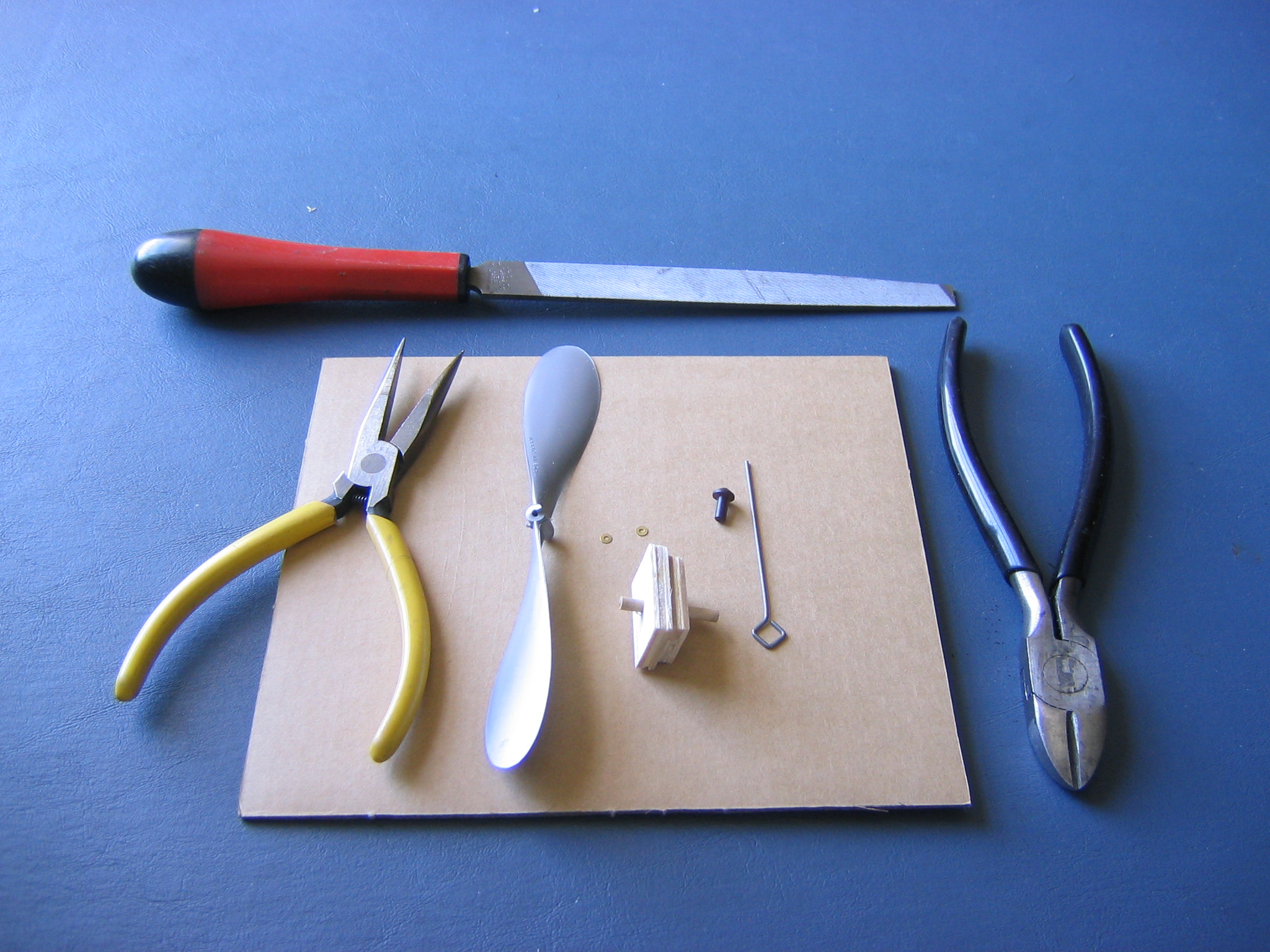
a 6″ plastic propeller, steel wire propeller shaft with motor hook bent in, two brass washers, Nylon prop bearing, balsa nose block, needle nose pliers, wire cutter and file. Push the Peck Nylon prop bearing into the hole in the front of the noseblock. Put the prop shaft through with the hook at the back. Thread on two brass washers and the prop. Note that the rounded end of the prop hub goes toward the bearing, the end with the helical ramp goes to the front.
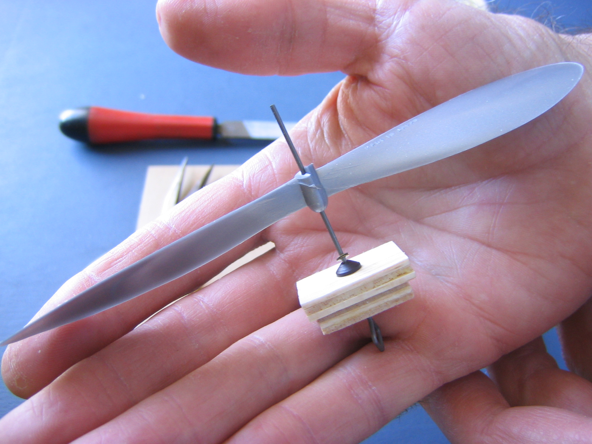
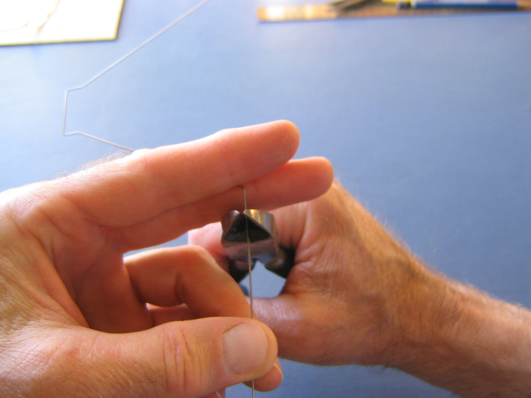
Hold the shaft in the pliers and bend the wire over to a bit more than a right angle with a block of wood. The bend will be about 1/8″ beyond the face of the prop with the hook pulled up to the back of the noseblock.
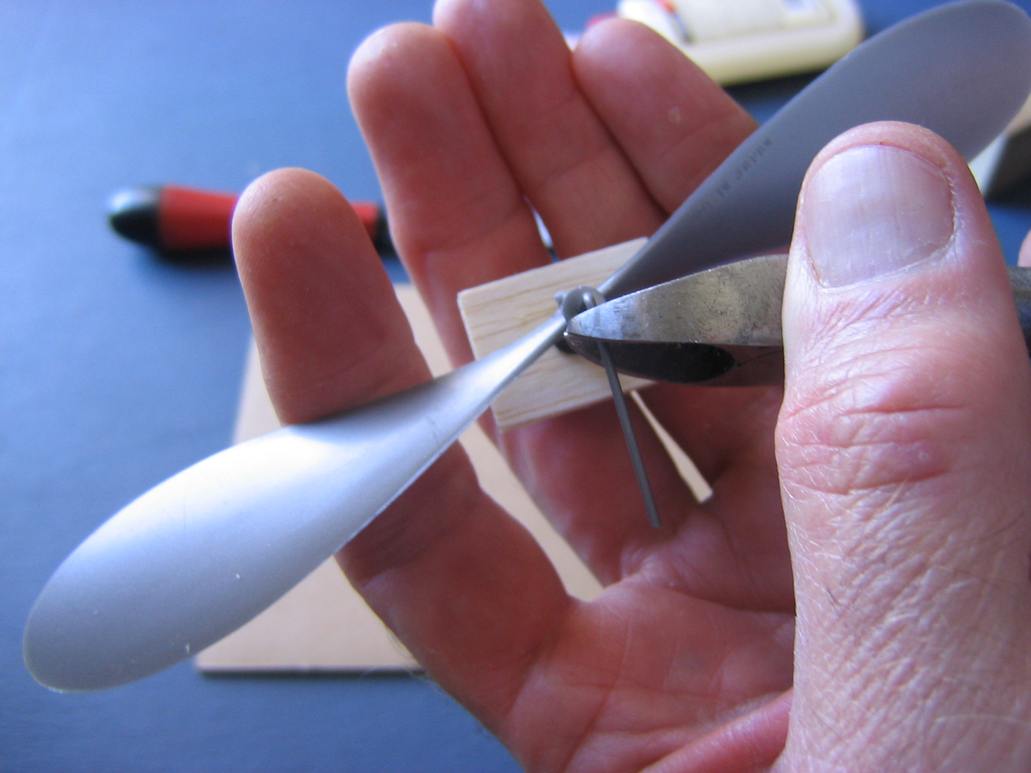
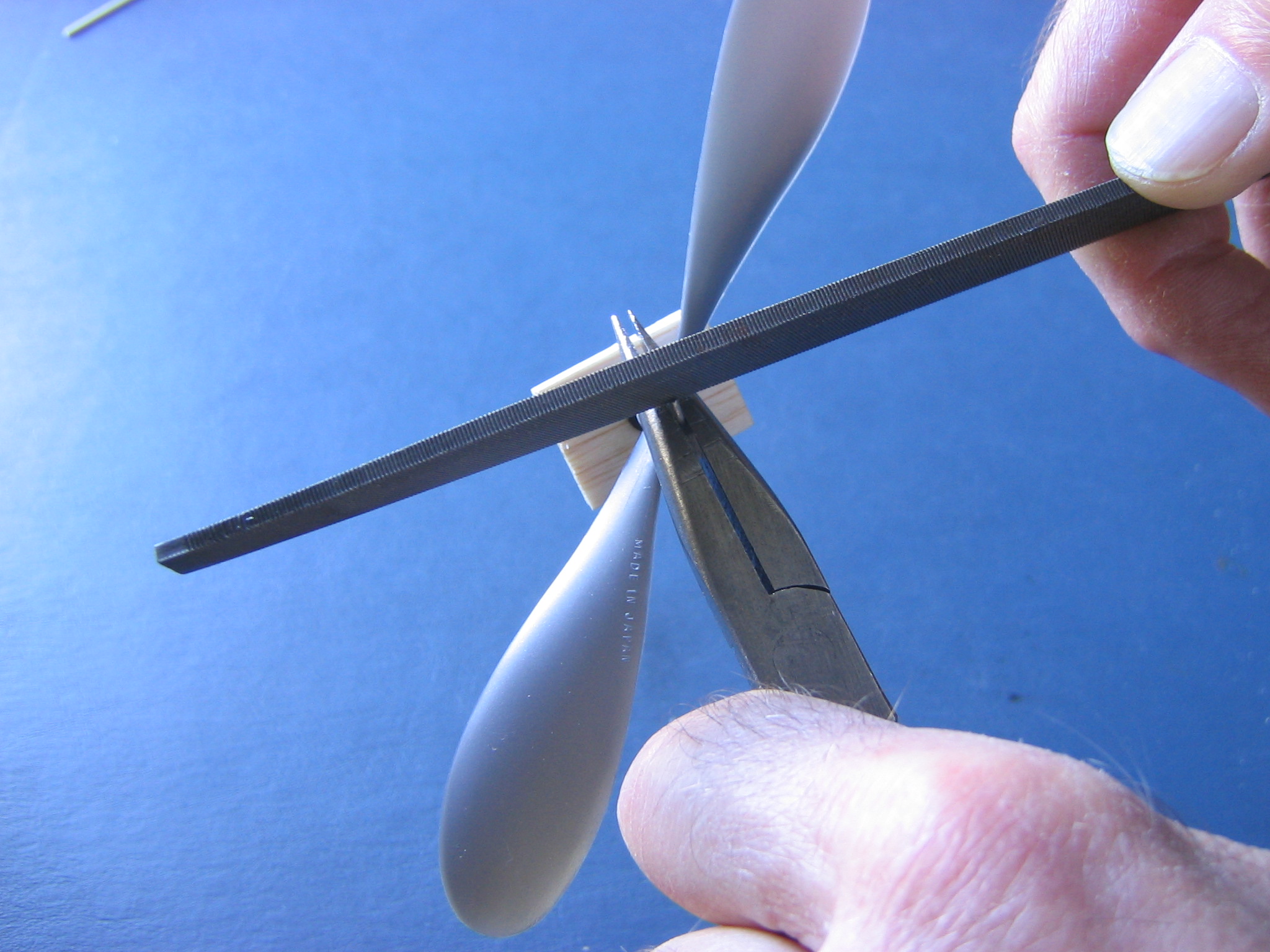
Cut the wire off just beyond the face of the hub, being careful, since the sharp piece of wire can shoot off at considerable speed. It is best to hold it between fingers or wrap the end in cloth to catch it.
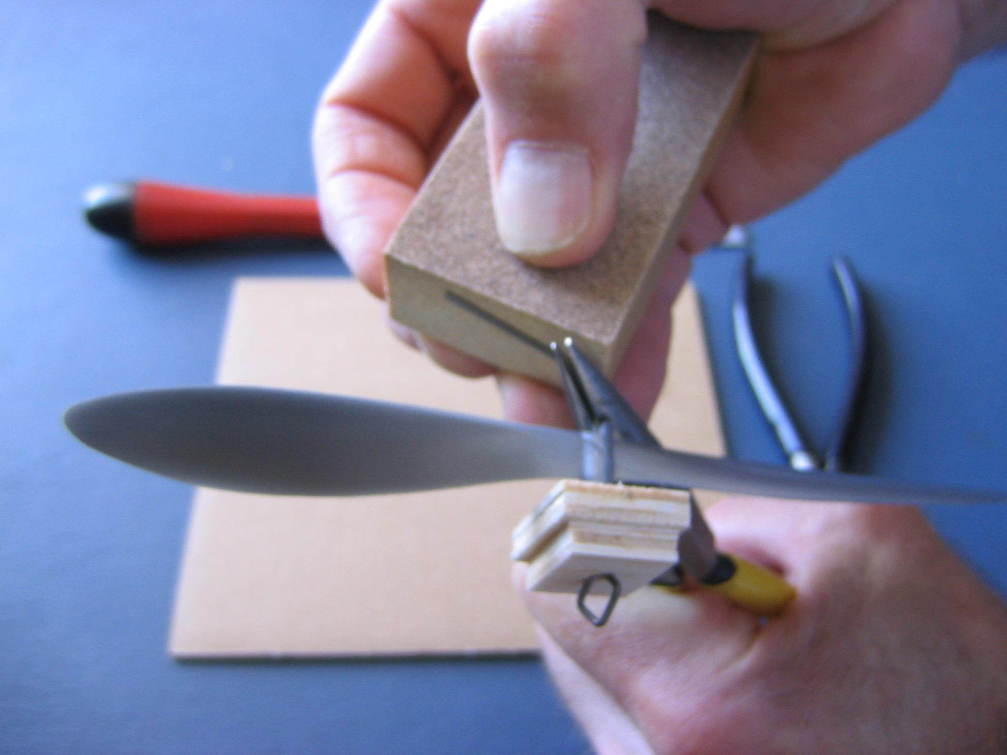
Finally, file off the sharp chisel end left by the wire cutter.
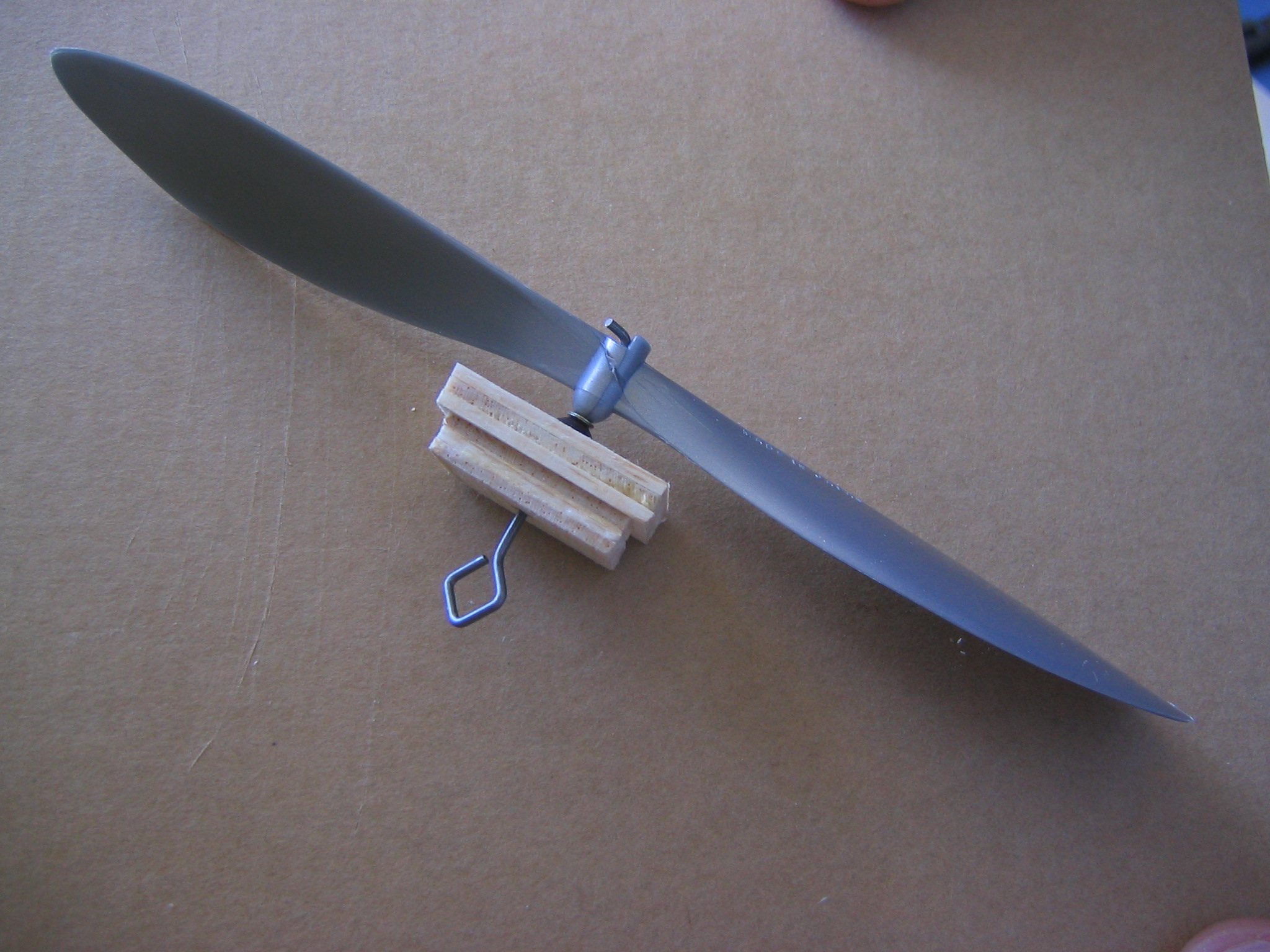
Here is the finished prop assembly. Gosh, that was quick!
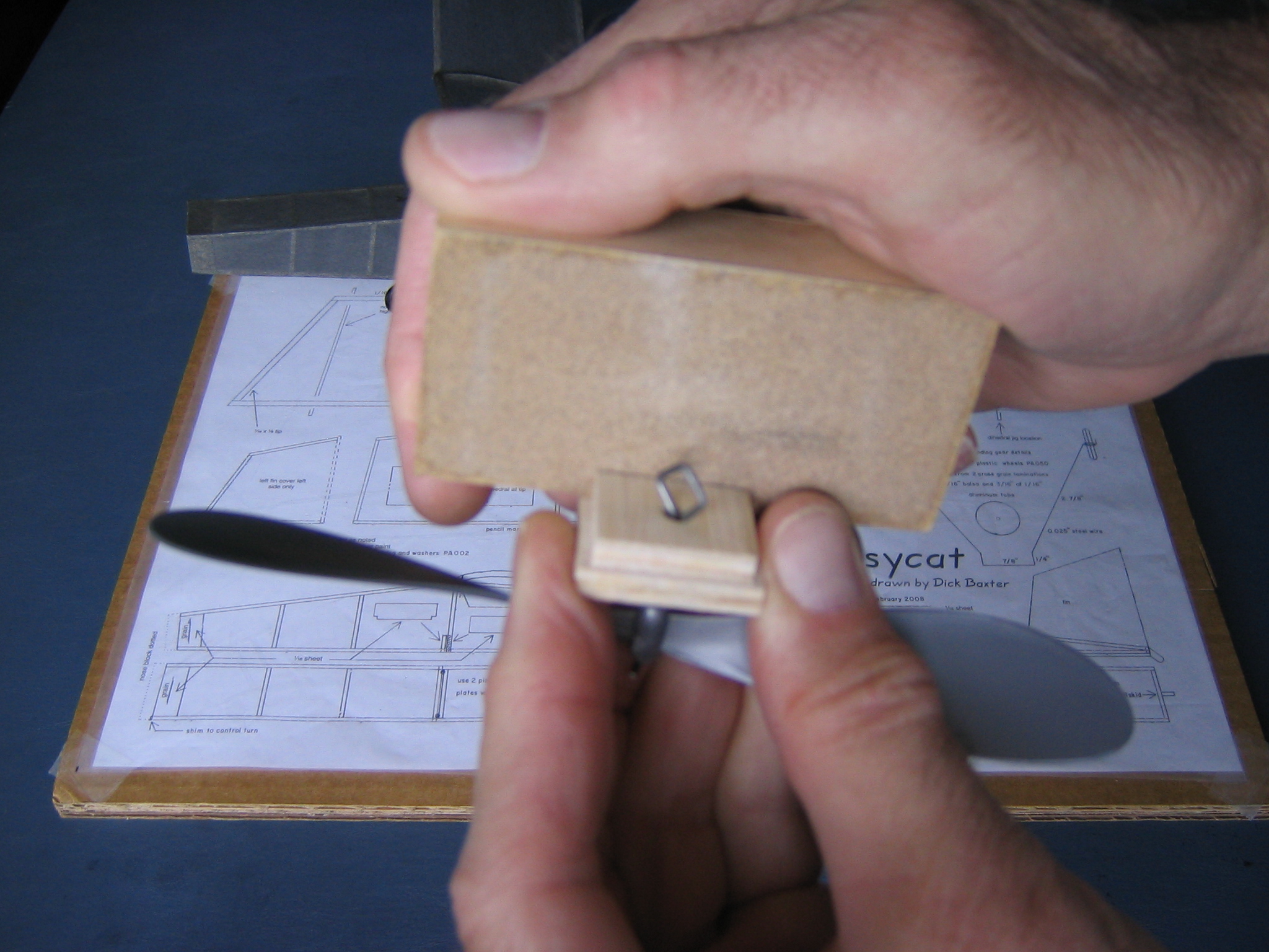
Check the fit in the fuselage. If it is too big, sand it lightly and test fit, sanding just a little at a time. You can’t put the wood back on, but if you overdo it, you can usually glue tissue or other paper on the faces to build it back up.
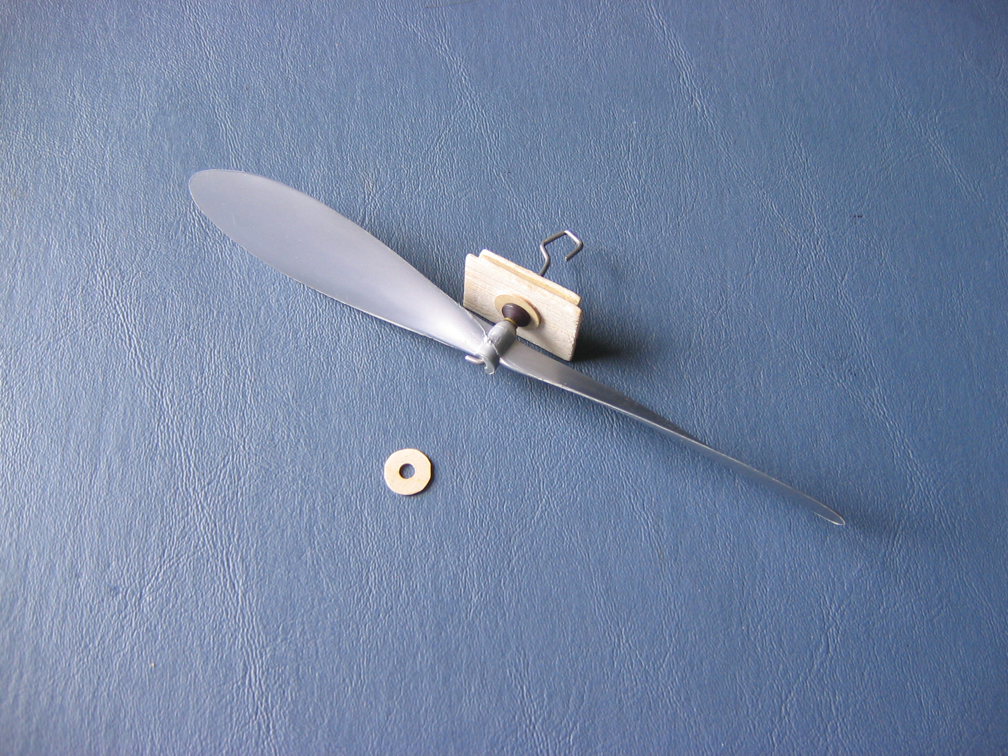
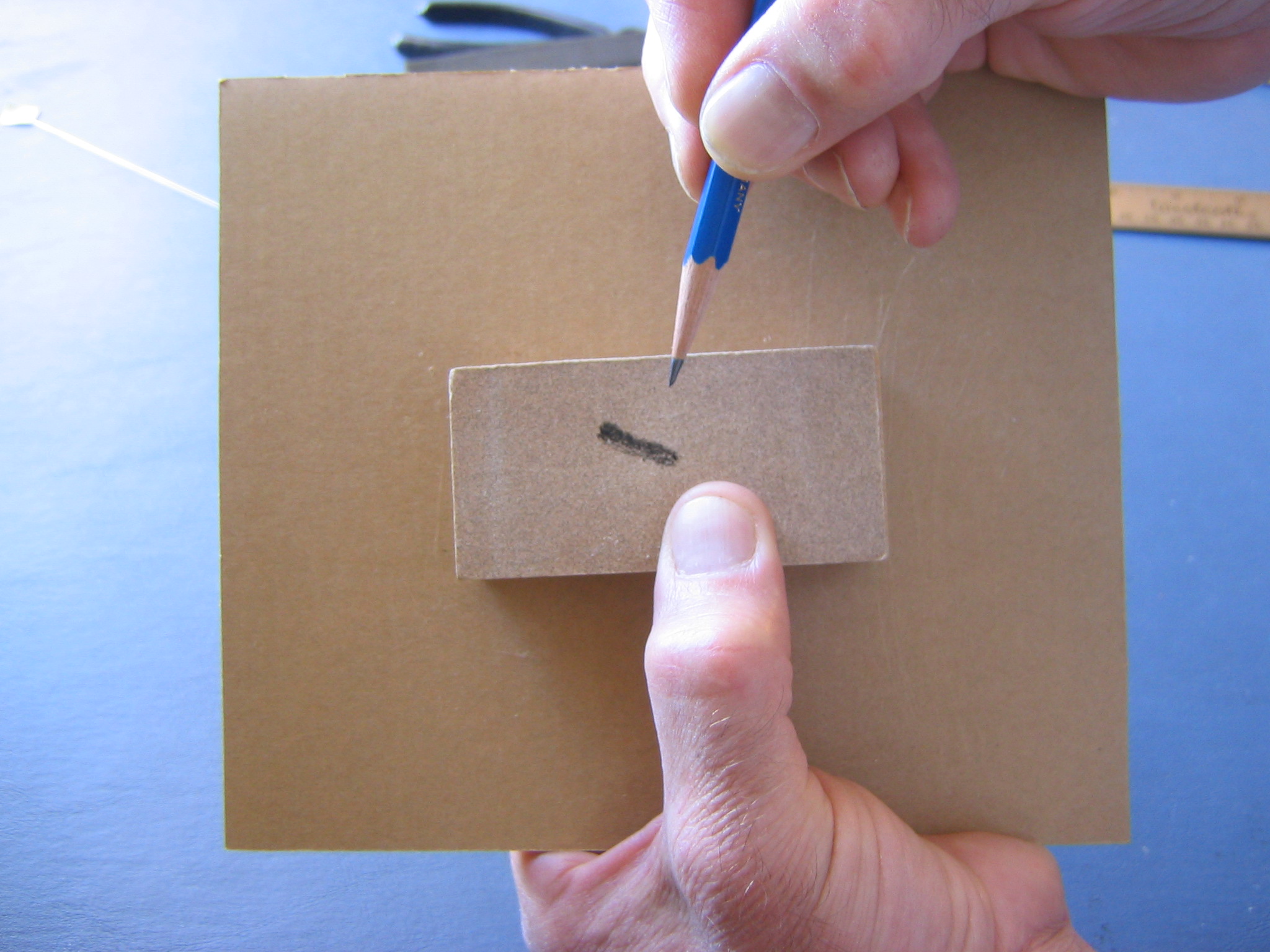
After flight testing my Big Pussycat in the Gym, I decided to make a lighter noseblock with three layers of balsa sheet instead of six, so I could use a lighter motor. After the prop strikes a few obstacles, the bearing gets loose and the prop may not point where you want it. I reinforced the face with a 1/32″ ply washer to prevent the nylon propshaft bearing from wobbling. Draw a 3/8″ circle on some 1/32″ ply, cut it out with scissors, sand the edge smooth and drill a 1/8″ hole in the center with the round file to be a snug fit around the prop bearing. Glue the washer to the face of the nose block.
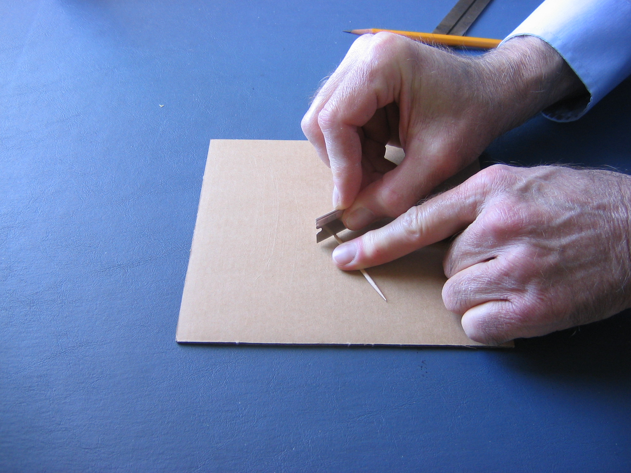
The motor peg is a 1 5/8″ piece of round wood toothpick. You can also make one from 1/16″ aluminum tube. These are cut to length by rolling them under the razor blade, keeping the edge of the blade perpendicular to the stick. You can do the same with aluminum tube.
Making the Landing Gear
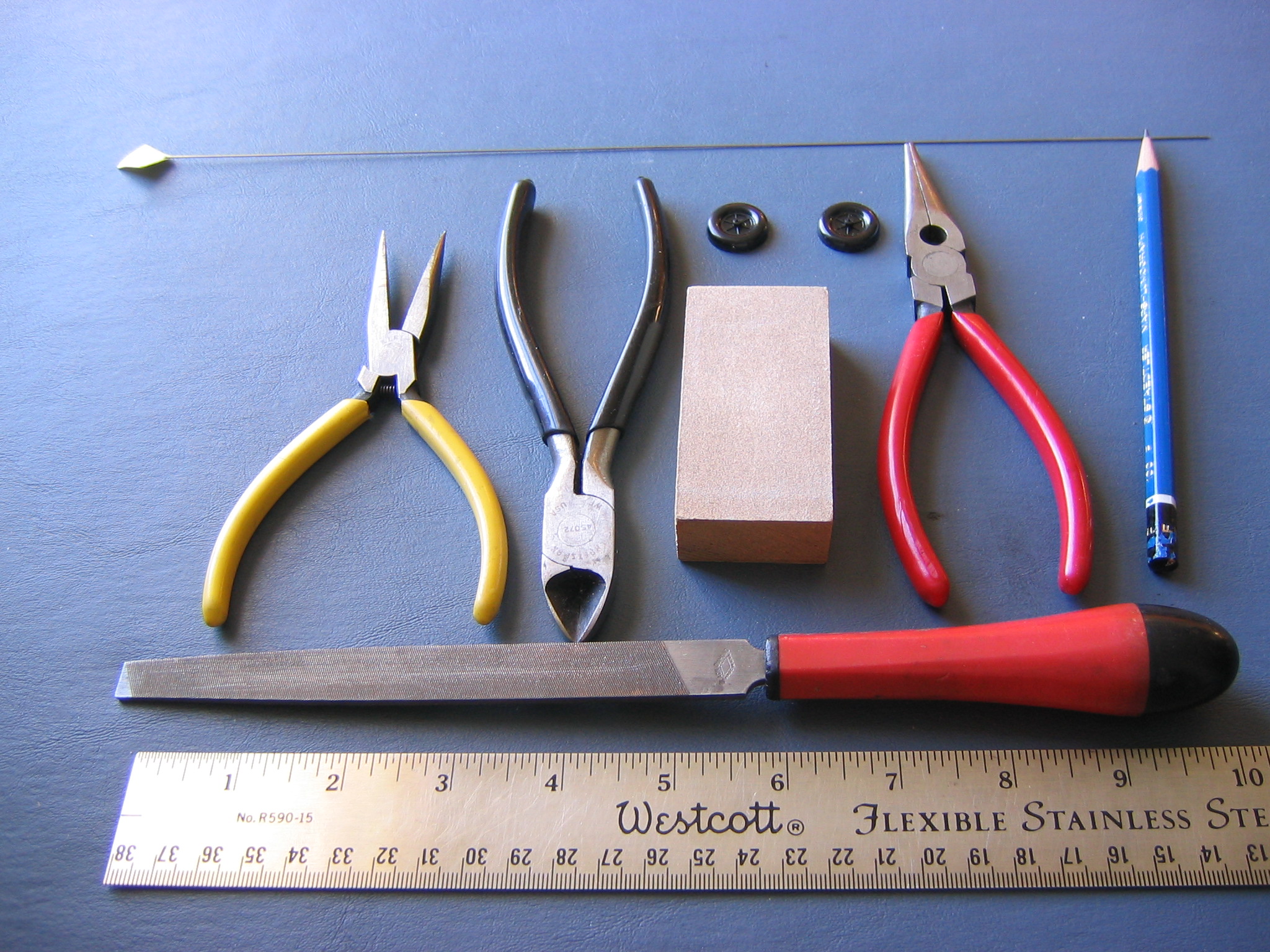
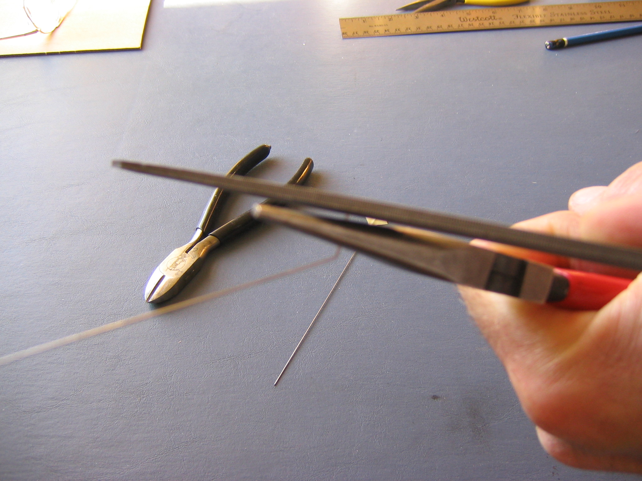
You will need needle nose pliers, wire cutter, file, tape, sharp pencil, block of wood, plan, 8″ of 0.025″ steel wire and two 3/4″ wheels.
This can be difficult if you have not done it before. It takes me a half hour to bend a landing gear wire. Allow yourself plenty of time without distractions or interruptions, be patient, take your time.
Cut wire ends are as sharp as chisels. Be careful not to poke yourself in the eye or elsewhere. Fold bits of tape onto the ends of the wire to cover the points.
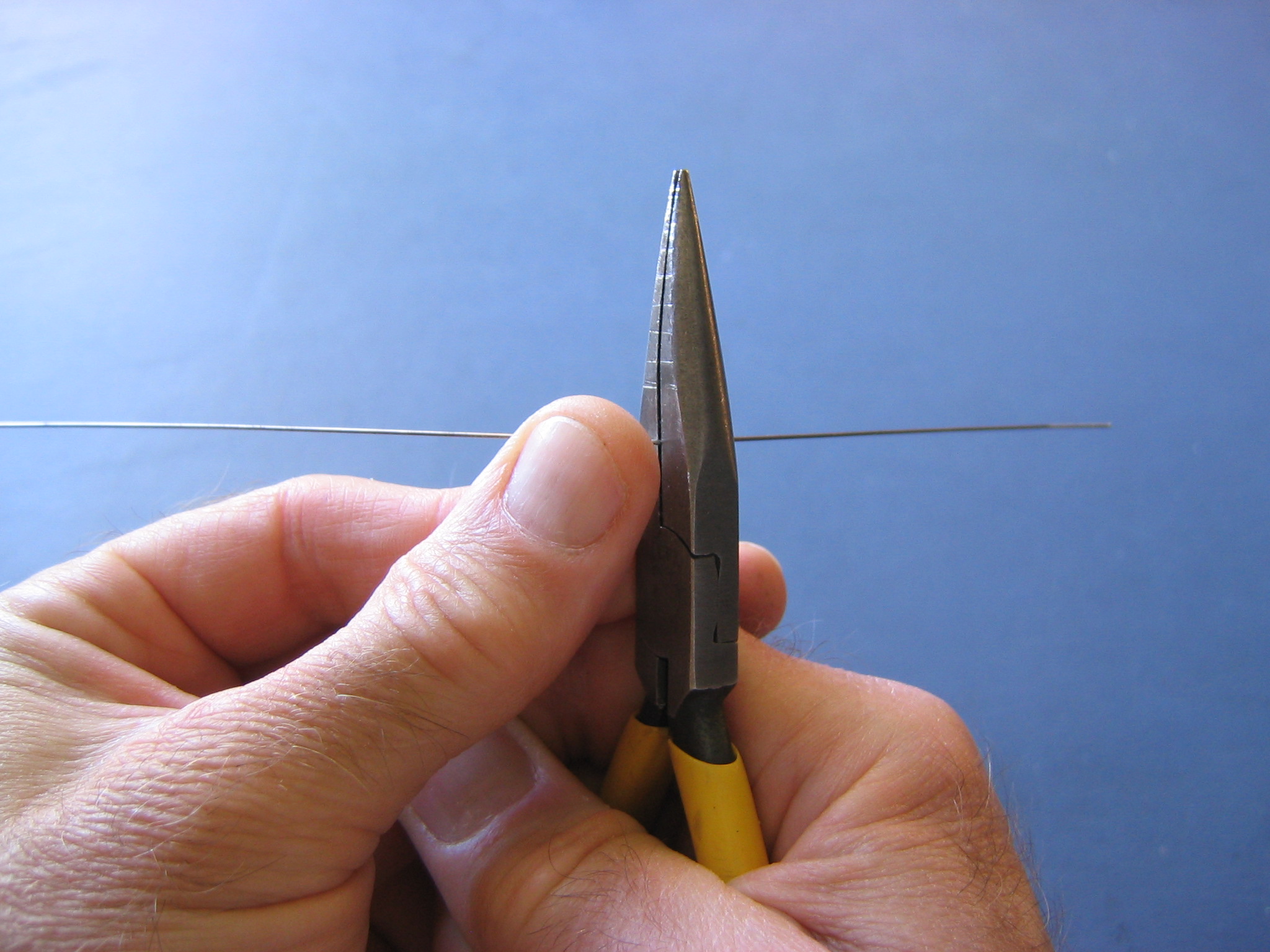
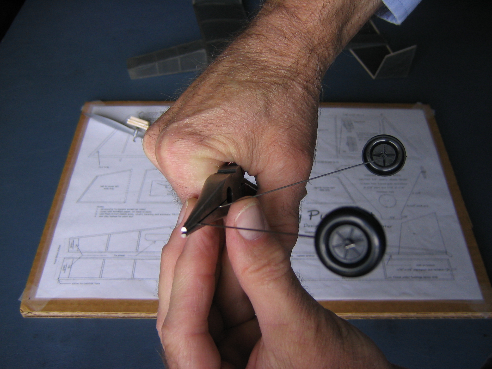
There are some tricks to bending steel wire. There is a lot of spring back in steel wire, so the bends must be slightly over done to come back to the right place. Hold the piece up so your eye is in the plane of the figure and align the bent piece and the adjacent piece in the same plane as you bend it. Bend the wire away from your face. The bend will take place just outside the face of the pliers, so the pliers must be positioned a bit back from where you want the bend. Make a sharp chisel point on the pencil by rubbing it on the fine sandpaper at an angle.
Start by filing one end of the wire to remove the sharp end. This sharp end will cut your fingers, I know from experience! Push the file at a right angle to the pliers.
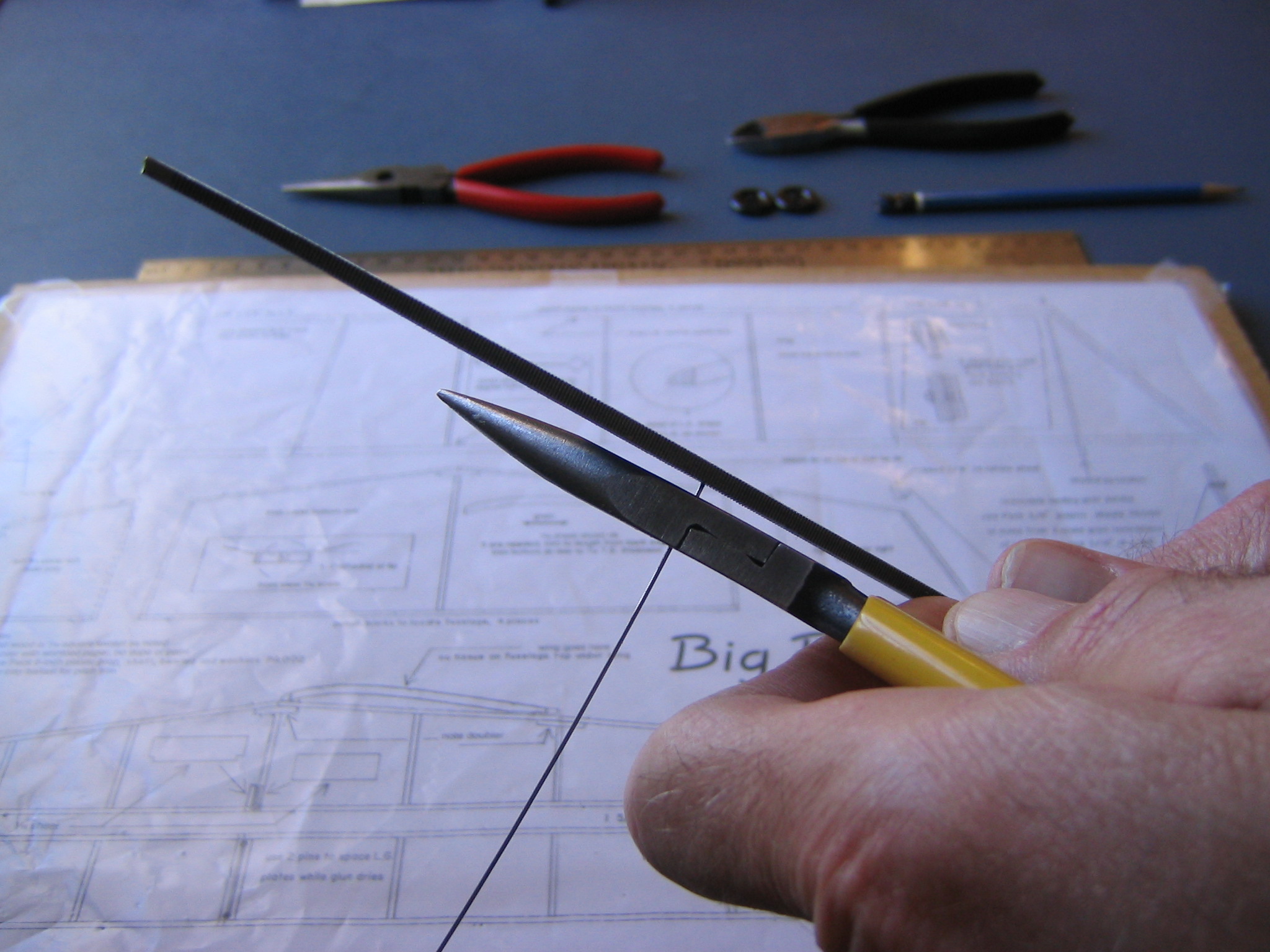
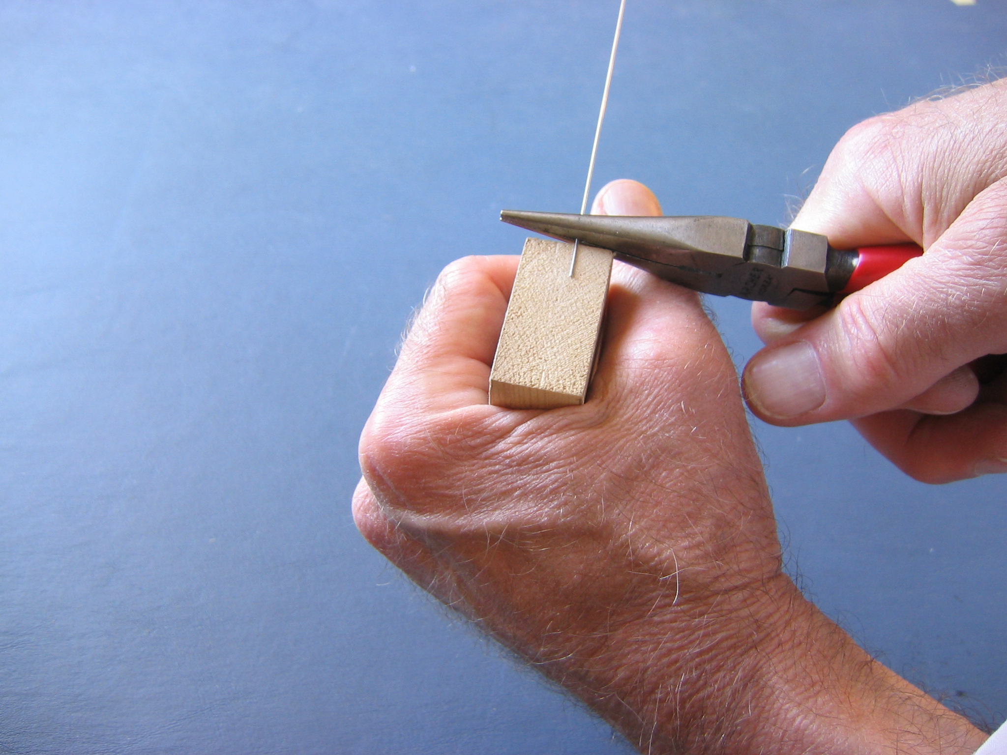
Push it through the pliers until 3/8″ sticks out.
It is hard to grip this short piece of wire, so push it against a block of wood to make the bend. Push in a direction perpendicular to the faces of the pliers, otherwise it will just slip and rotate between the faces of the pliers. You may find it easier to place the block on the table and press the end of the wire to the block with a rolling action of the pliers.
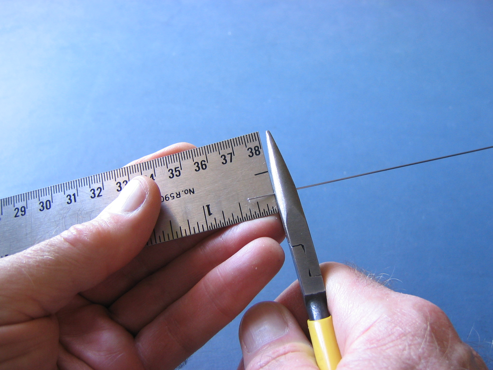
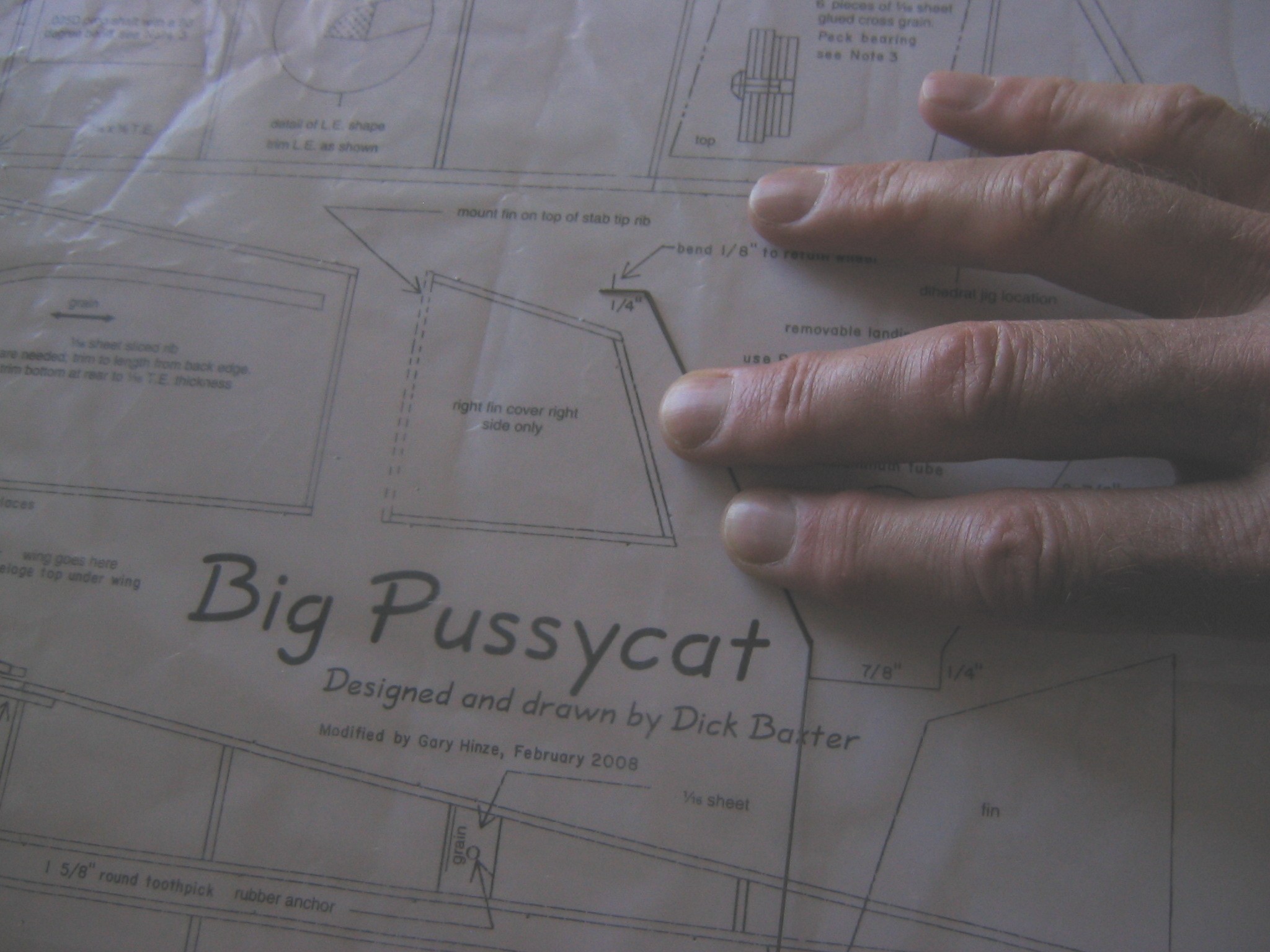
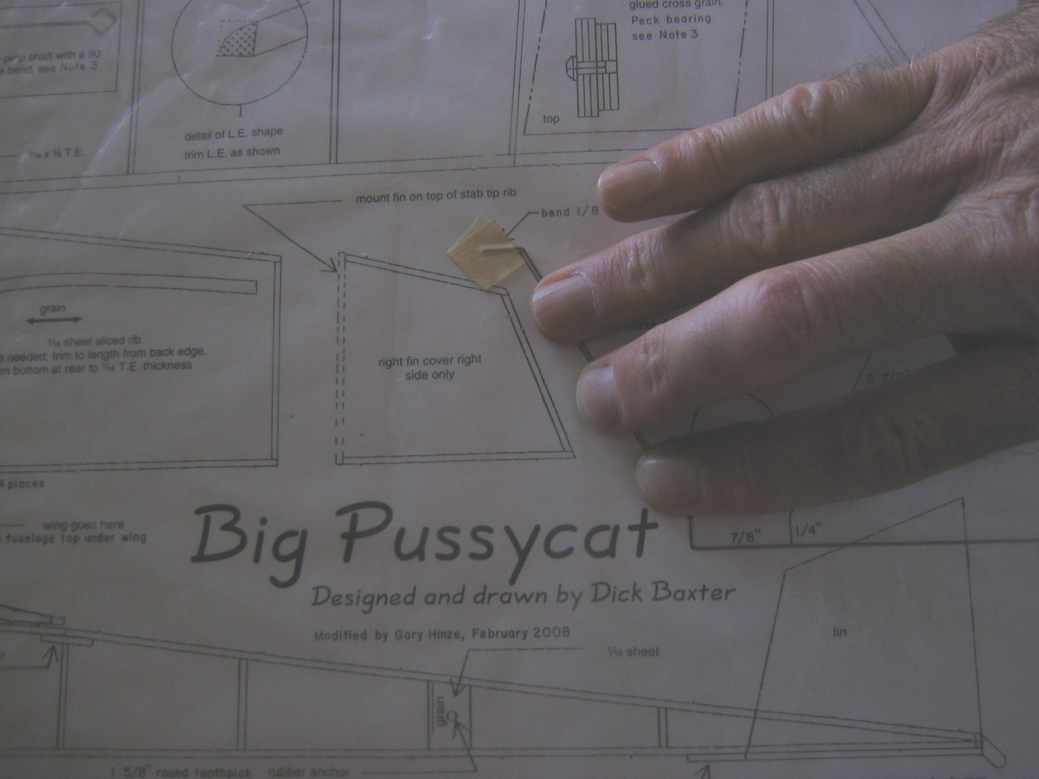
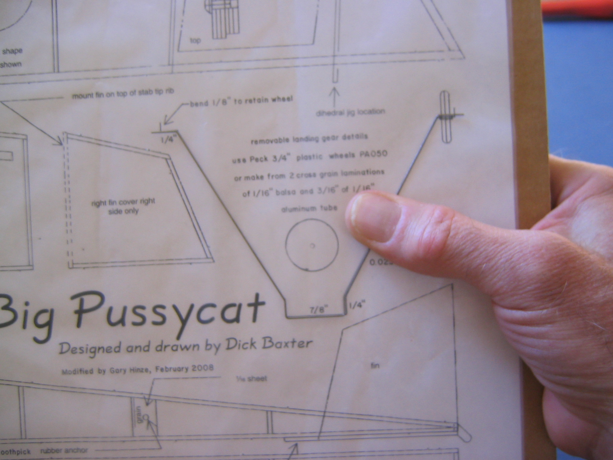
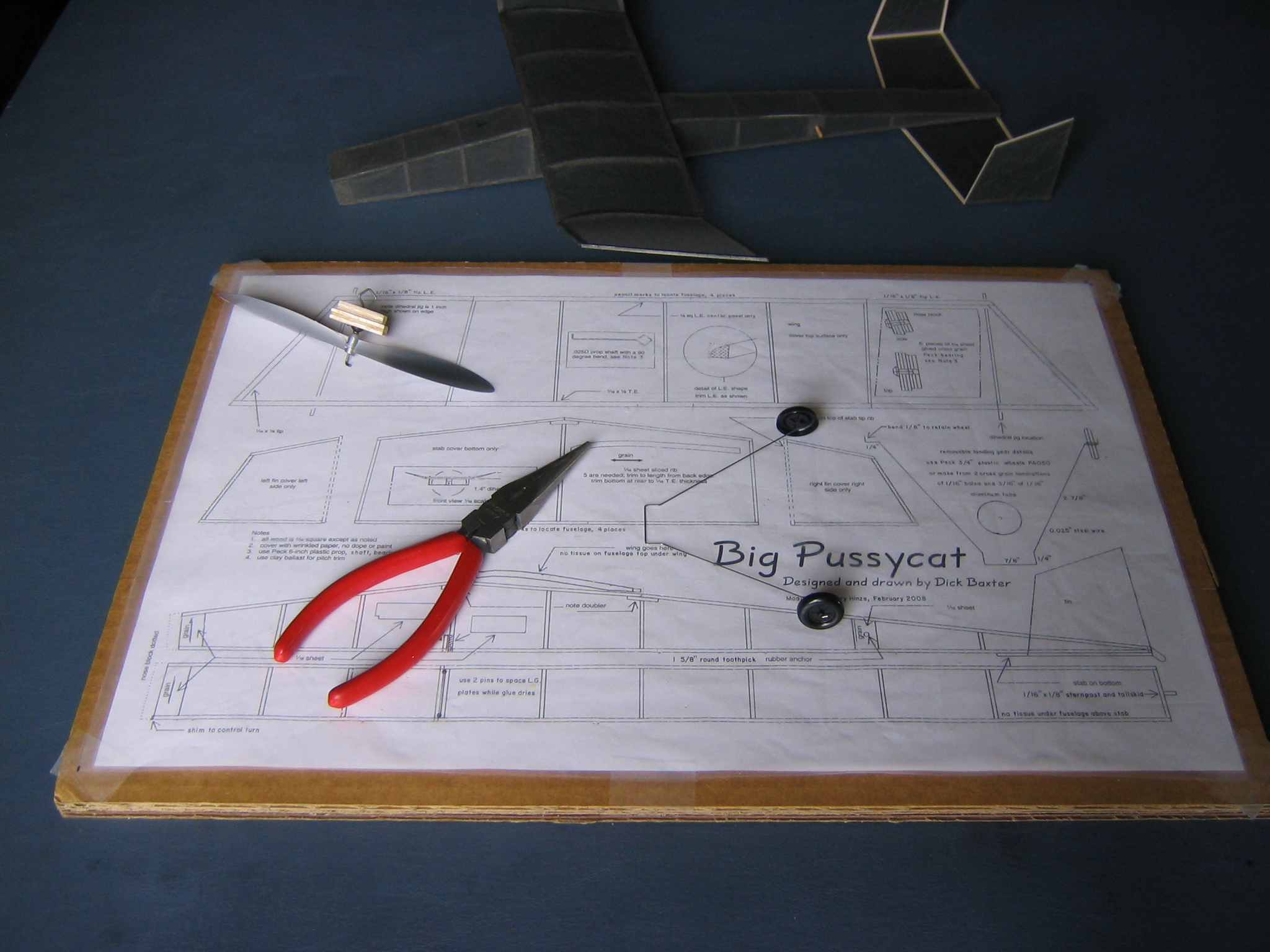
Lay the wire on the plan and check the bend.
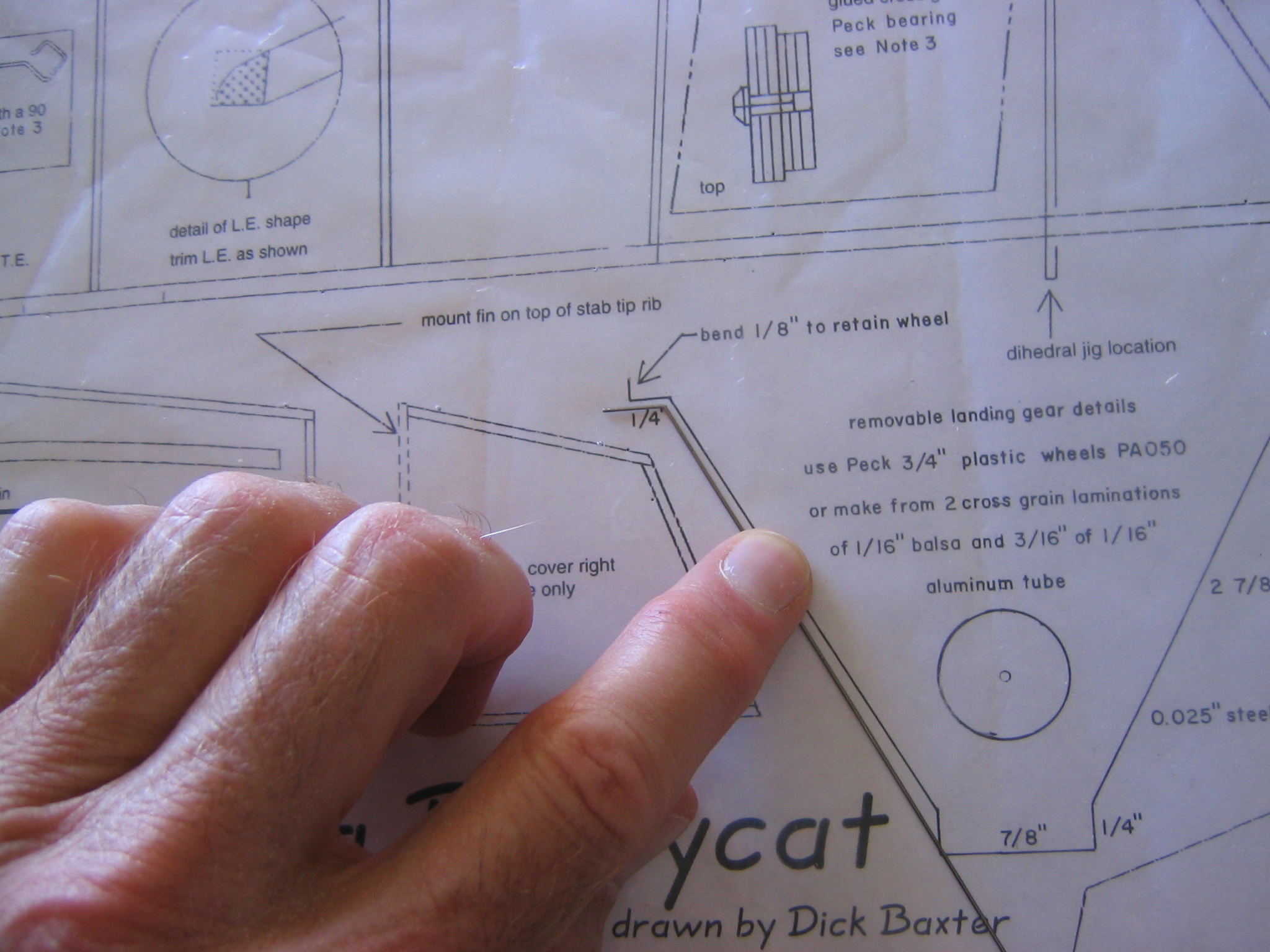
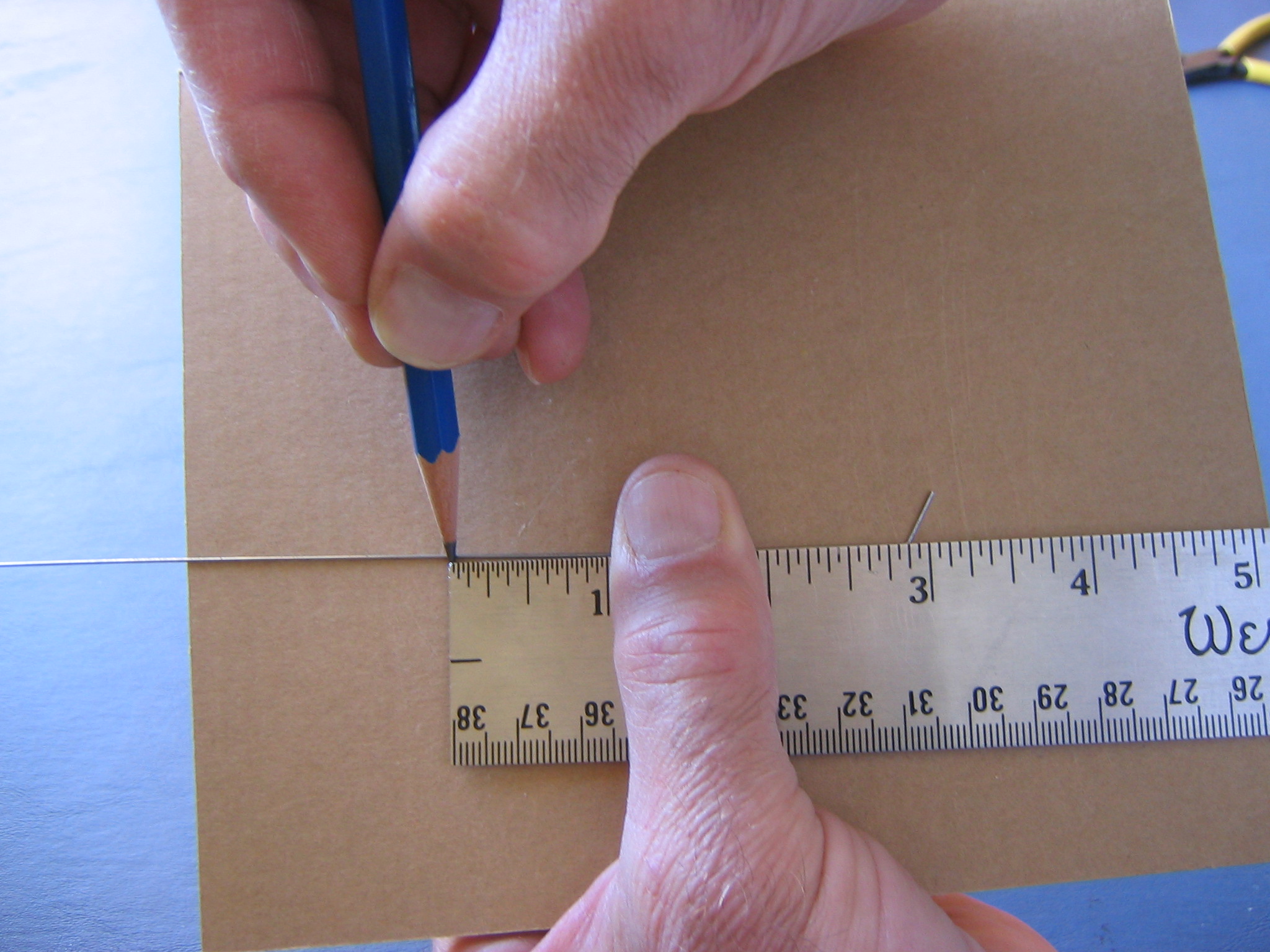
If it does not match the drawing, adjust it until it does. Note that the 1/8″ bend on the very end will not be made until all the other bends are done and the wheels are put on. Use the sharp pencil to mark a point 2 7/8″ away from the first bend. (Alternatively, cut narrow strips, 1/32″ wide, of masking tape to mark the locations of the bends. The pencil marks can be hard to see.)
Grip the wire tightly in the pliers at this mark, hold the pliers so the jaw is perpendicular to your line of sight, align the two pieces of wire and your eye in a plane perpendicular to the jaws and bend the wire, keeping all three sections of the wire in the same plane as your eye. Set it up so you are pushing the wire away from your face. Double check that you are bending it the right direction. This is a corollary to the saying “Measure twice, cut once.”
Did I say, be sure you are bending it the right way? Bending it back again will likely break the wire. When complete, lay the wire on the plan and check it. Adjust as necessary.
Make the next bend 1/4″ further along the wire and check it.
The next bend is critical. The length must be exactly 7/8″ between the outside faces of the wire, so it can fit snugly between the lower longerons. If you watched the last bend carefully, you noticed that the face of the wire ended about two wire diameters beyond the face of the pliers. So mark the next length with the pencil or tape accordingly, about two wire diameters back from 7/8″ from the face of the last 1/4″ side and place the face of the pliers right on the mark. When done bending, check that it is a snug fit in the slot under the fuselage.
Bend another 1/4″ length, then another 2 7/8″ length, then the final leg, cut to 3/8″ long.
File the chisel point off.
One last time, lay it on the plan and check it, making any necessary adjustments.
Slide a wheel onto one axle, making sure the outside face of the wheel faces to the outside, grip the axle with the pliers atabout 1/8″ from the last bend, with 1/8″ of wire extending beyond the face of the pliers and bend the remaining 1/8″ end over, using the face of another metal tool to push the wire.
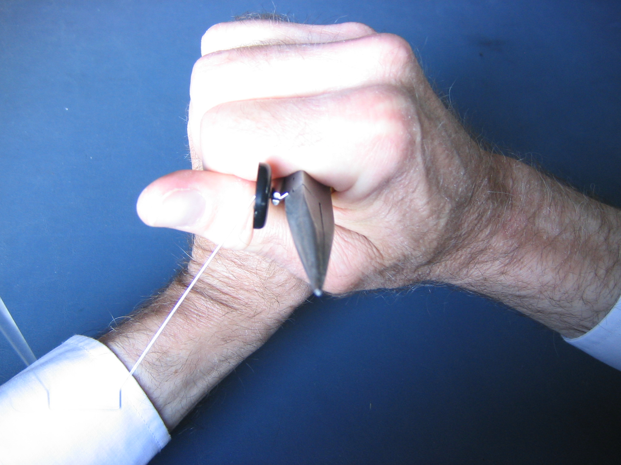
The amount of force required to bend the wire with this short leverage will force the wire into a wood block. Another way to do this is to put the other tool down on the table and force the end of the wire against it at an angle, with a rolling action of the pliers. Do the opposite wheel in the same way.
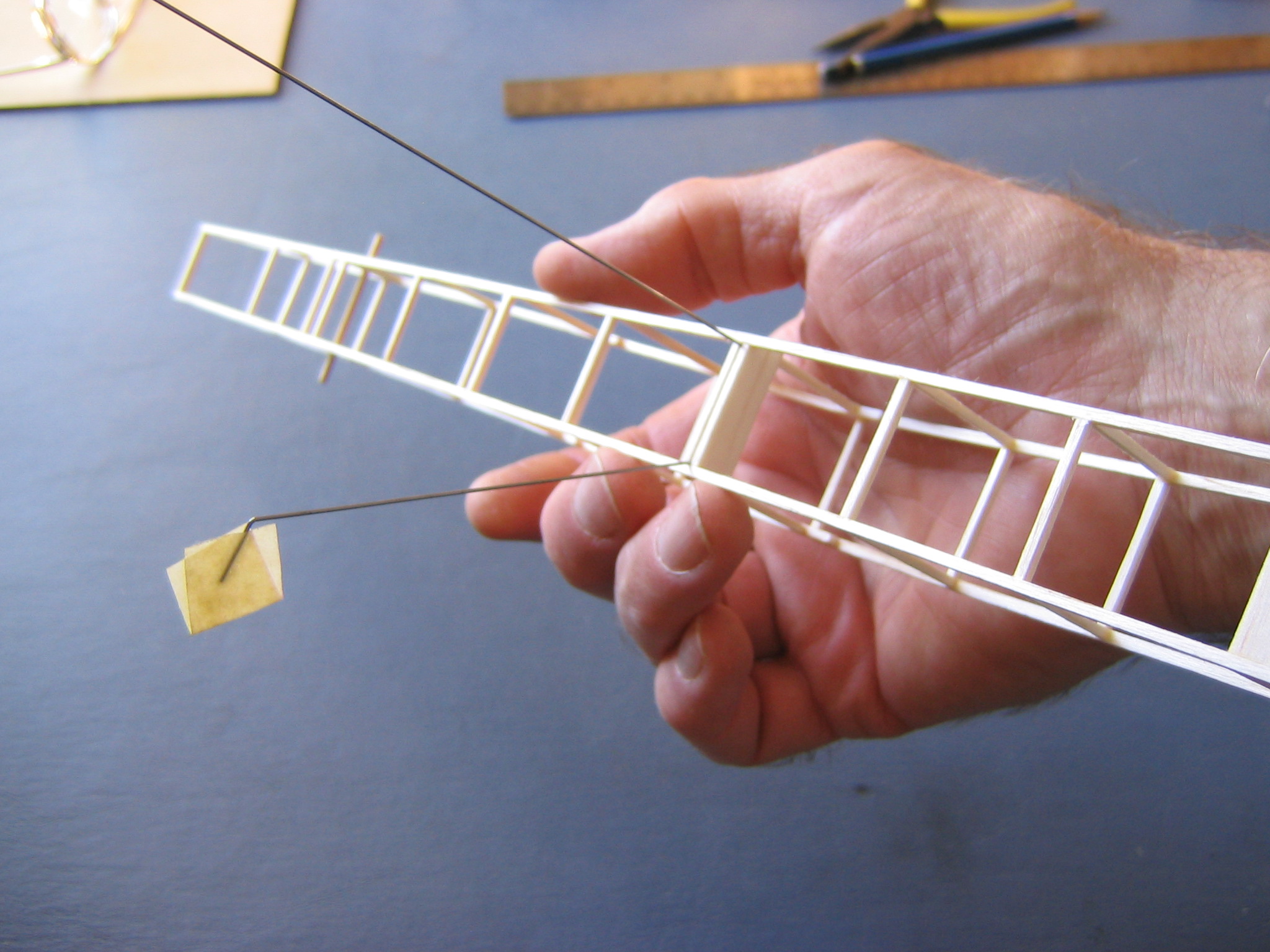
Push the wheels together slightly and insert the top bar into the slot under the fuselage, leading with one corner.
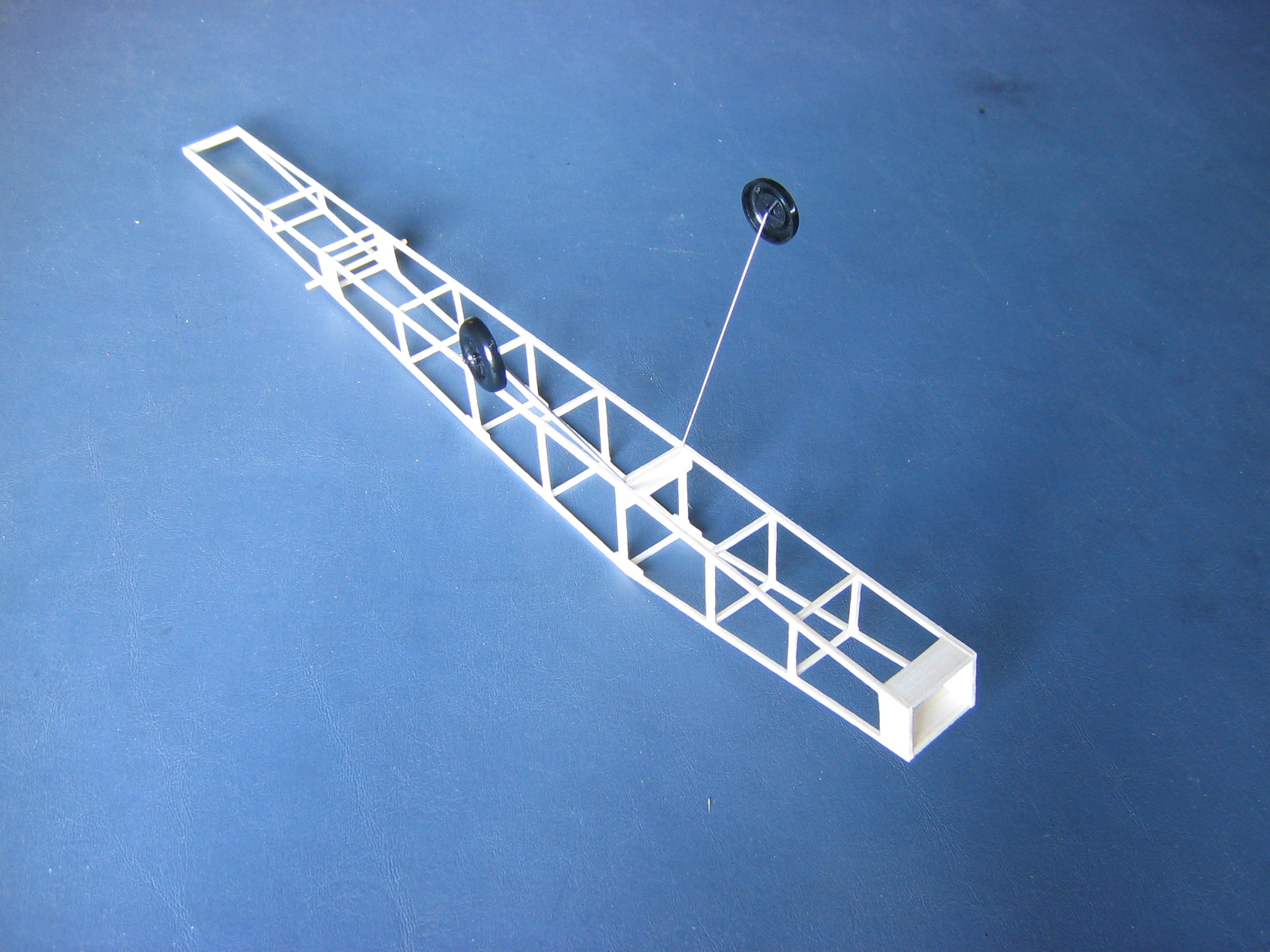
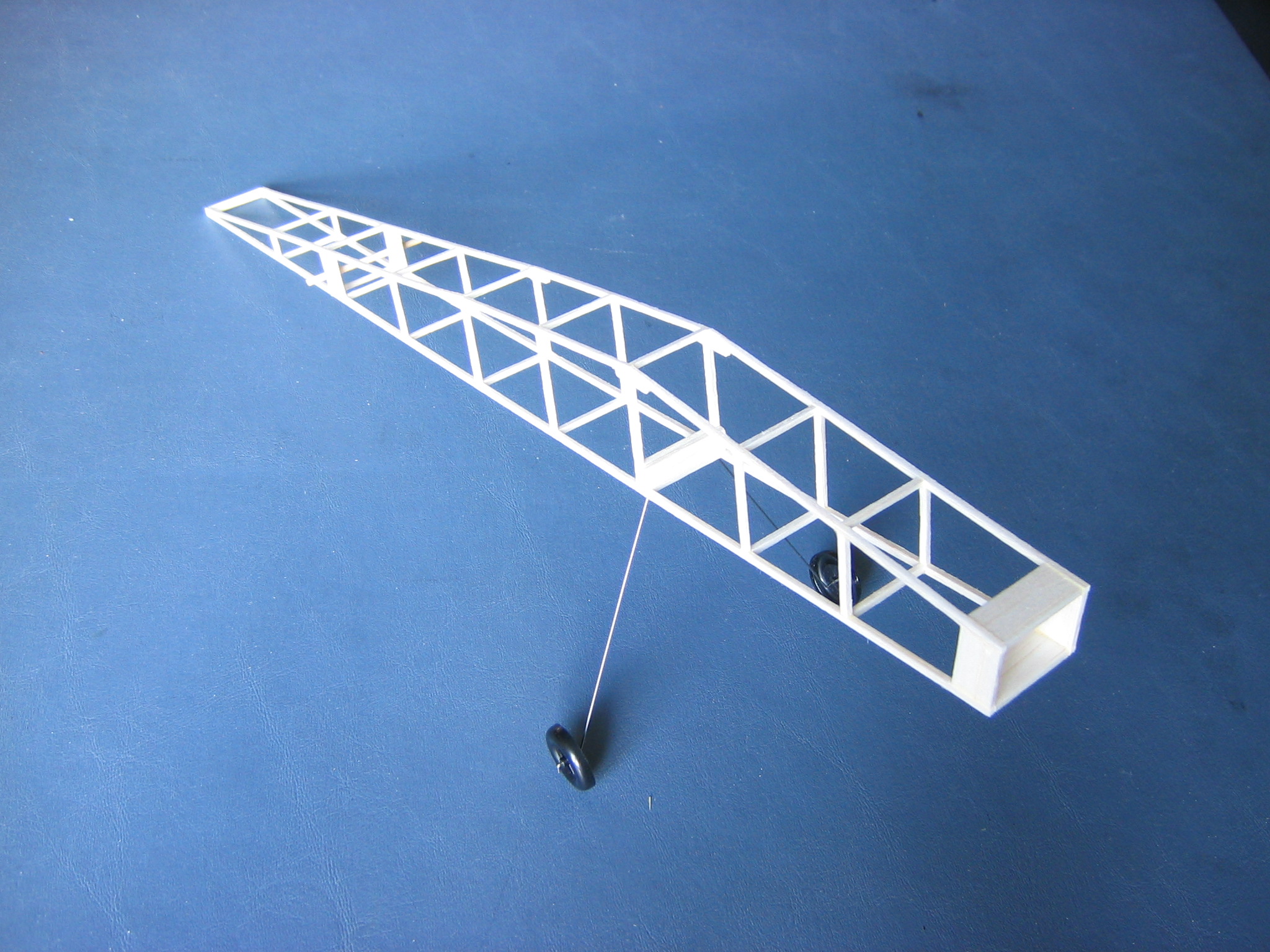
Later I found that the prop hits the ground on takeoff. The simplest solution is to bend the legs a bit forward, so the back of the wheels will be just below the slot.
The wire box at the top will lie flat on the table when you do that.
Click HERE to go to Chapter 7.
One thought on “Big Pussycat Chapter 6 – Making the Propeller and Landing Gear Assemblies”