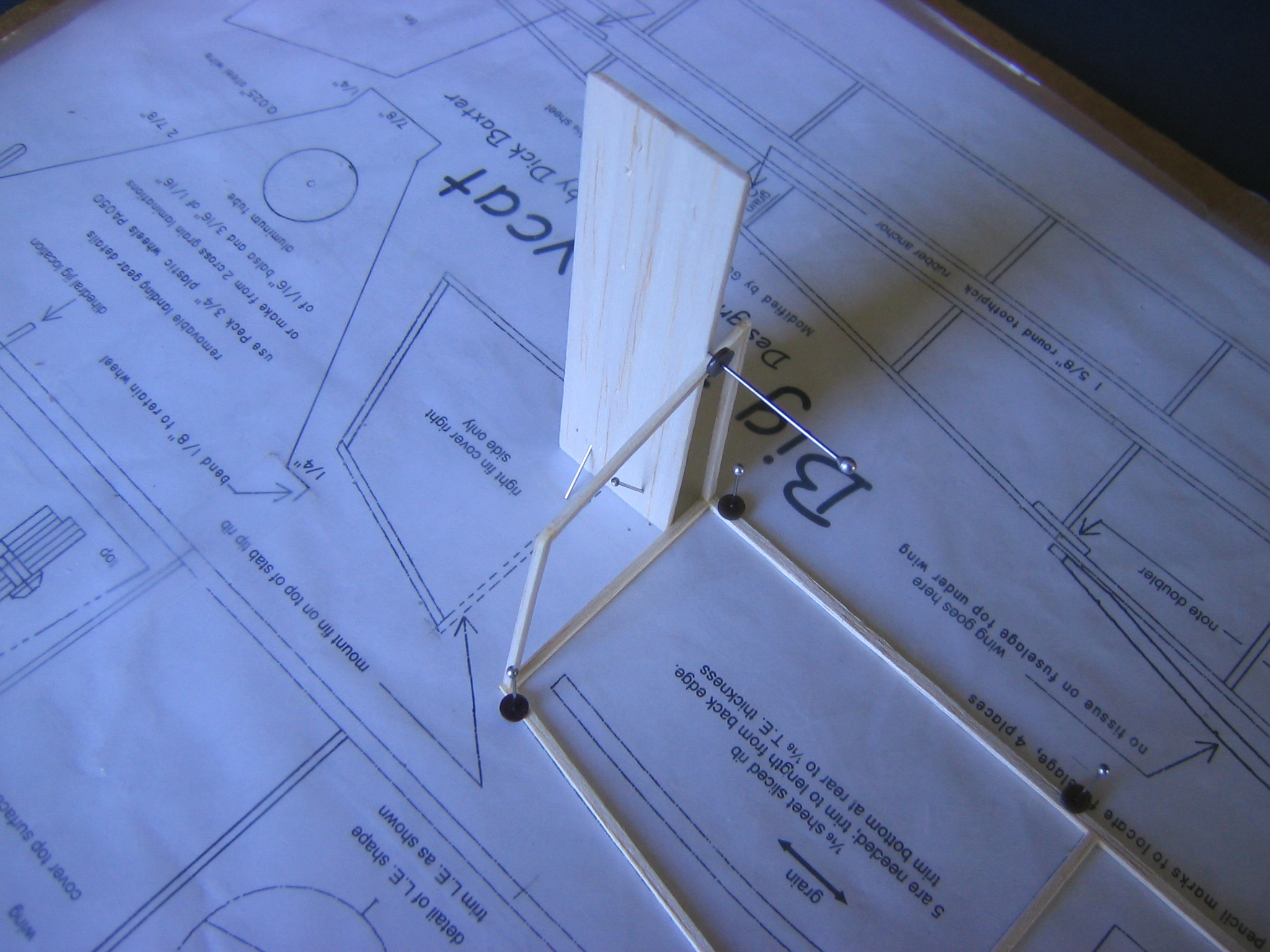
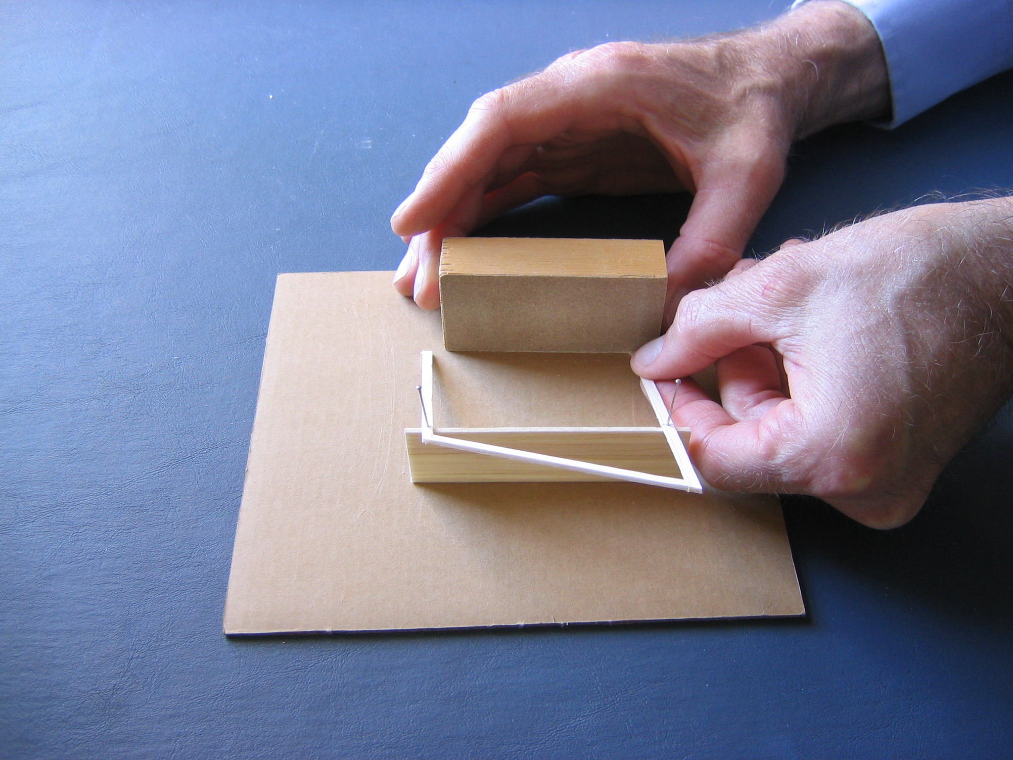
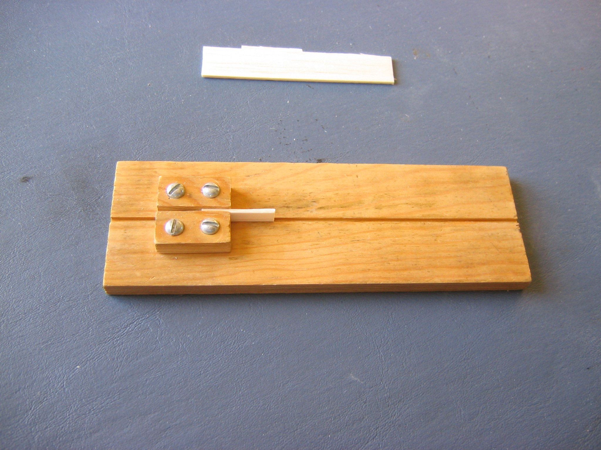
Glue the Fins to the Tailplane
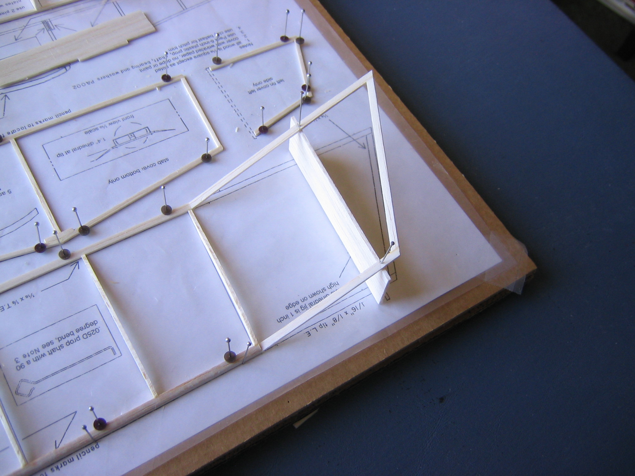
Pin the 1/16″ x 1″ x 3 ½” jigs up against the tailplane tips with the 1″ ends in firm contact with the board, using two pins going at 45 degree angles from opposite sides. Be sure the bottom edge of the jig is in firm contact with the board and the edge is in contact with the tailplane end rib. Put glue on the ends of the fin sticks and on top of the tailplane, press the back end to the back corner of the tailplane and the front end wherever it falls, then put a pin clamp into the jig just above the top fin stick to hold it in place while the glue dries. Check and make sure everything is in place so the fin will be perpendicular to the tailplane while the glue is drying. Do the same with the opposite fin. Check the plan to make sure the fin is pointing the right direction.
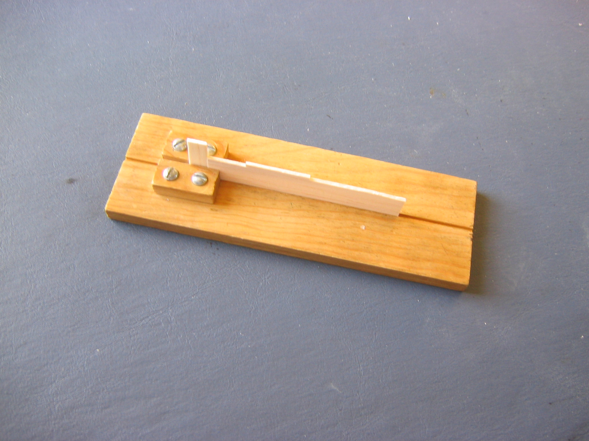
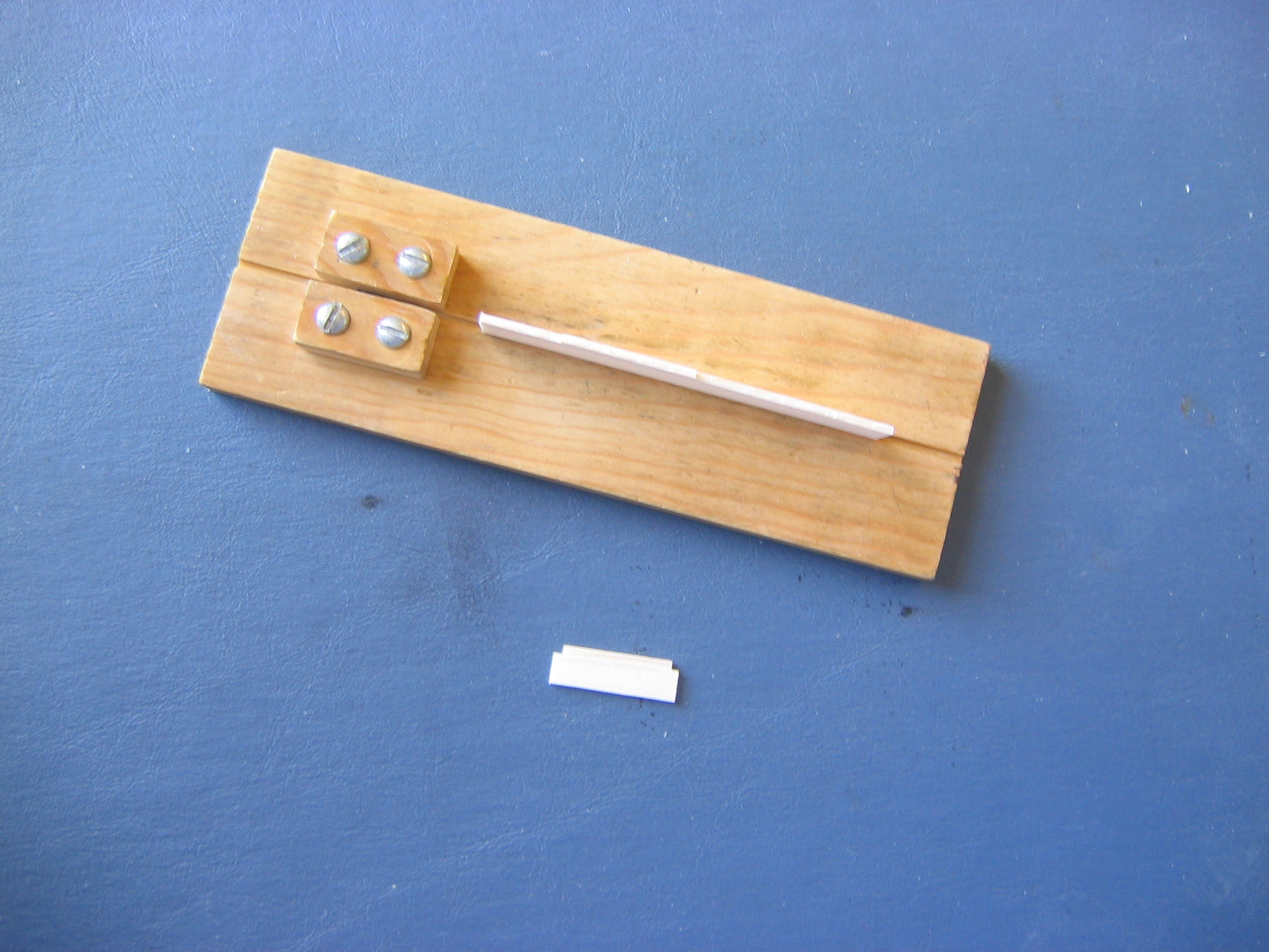
When the glue has dried, pry the tailplane unit up from the plastic sheet and put it in a safe place.
The finished tailplane and fin unit looks like this.
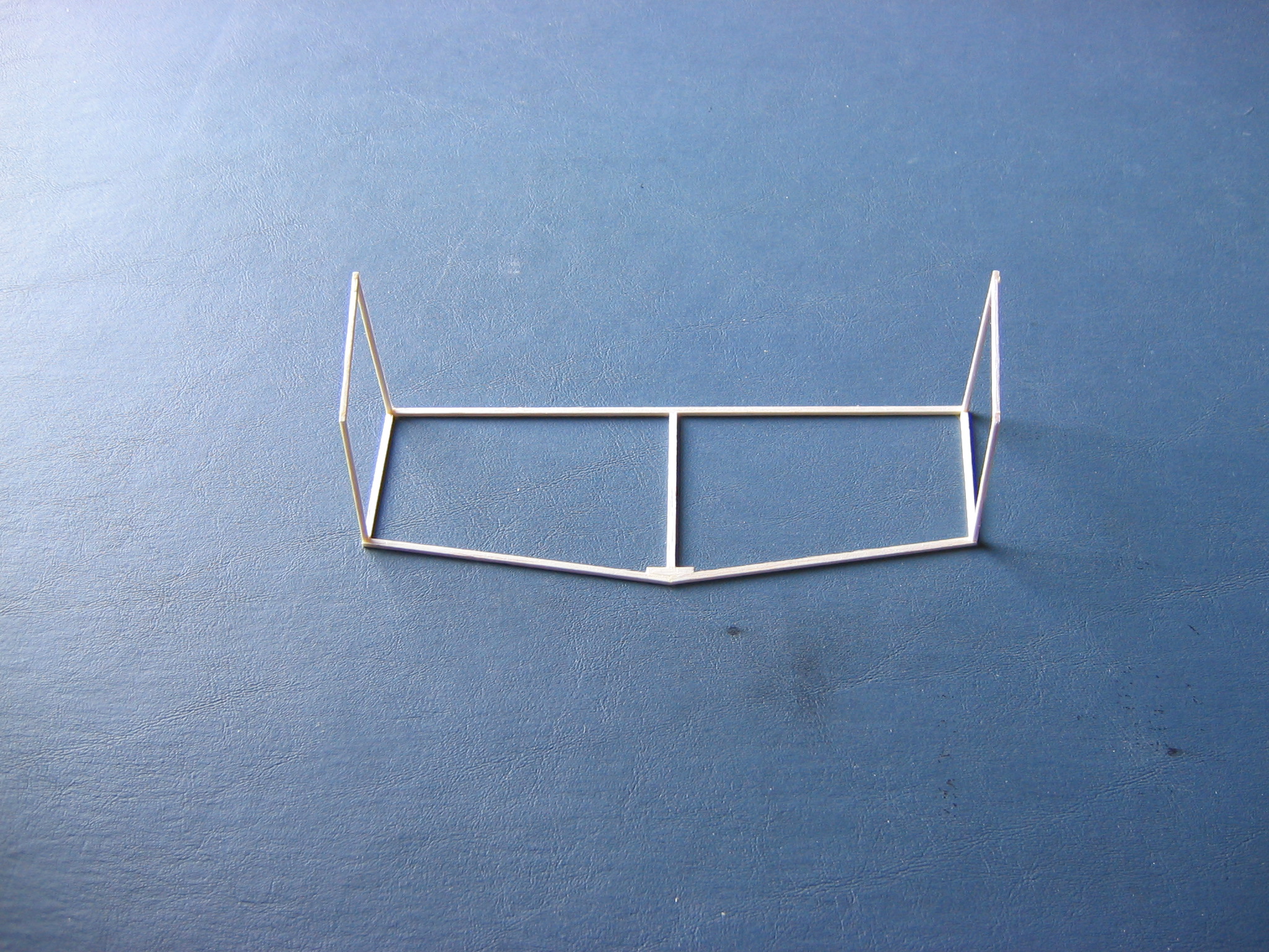
By a safe place, I mean a box or other container where it will be out of the way and protected from accidental damage. You’d be surprised how easy it is to whack the tailfin off while reaching for a pin or glue stick!
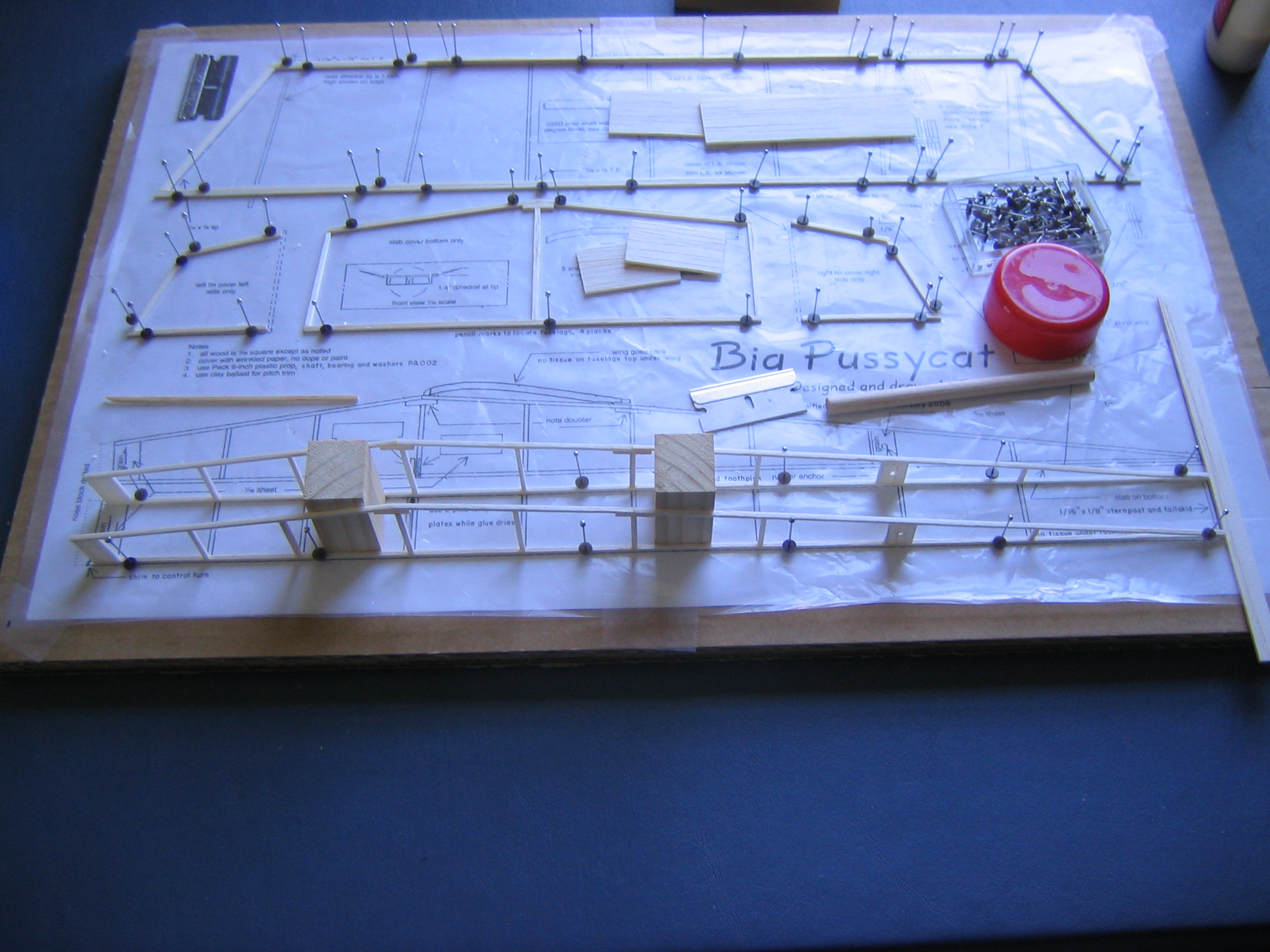
Sand the Dihedral Bevel and Glue the Wing Tips to the Center Panel
NOTE: The following is the way I built both of my Big Pussycats. On reflection, I would recommend covering the central panel of the wing with tissue BEFORE gluing the wingtips on. The wingtips get in the way of getting the tissue on the central panel, making a difficult job much more difficult. This is how our students build them now.
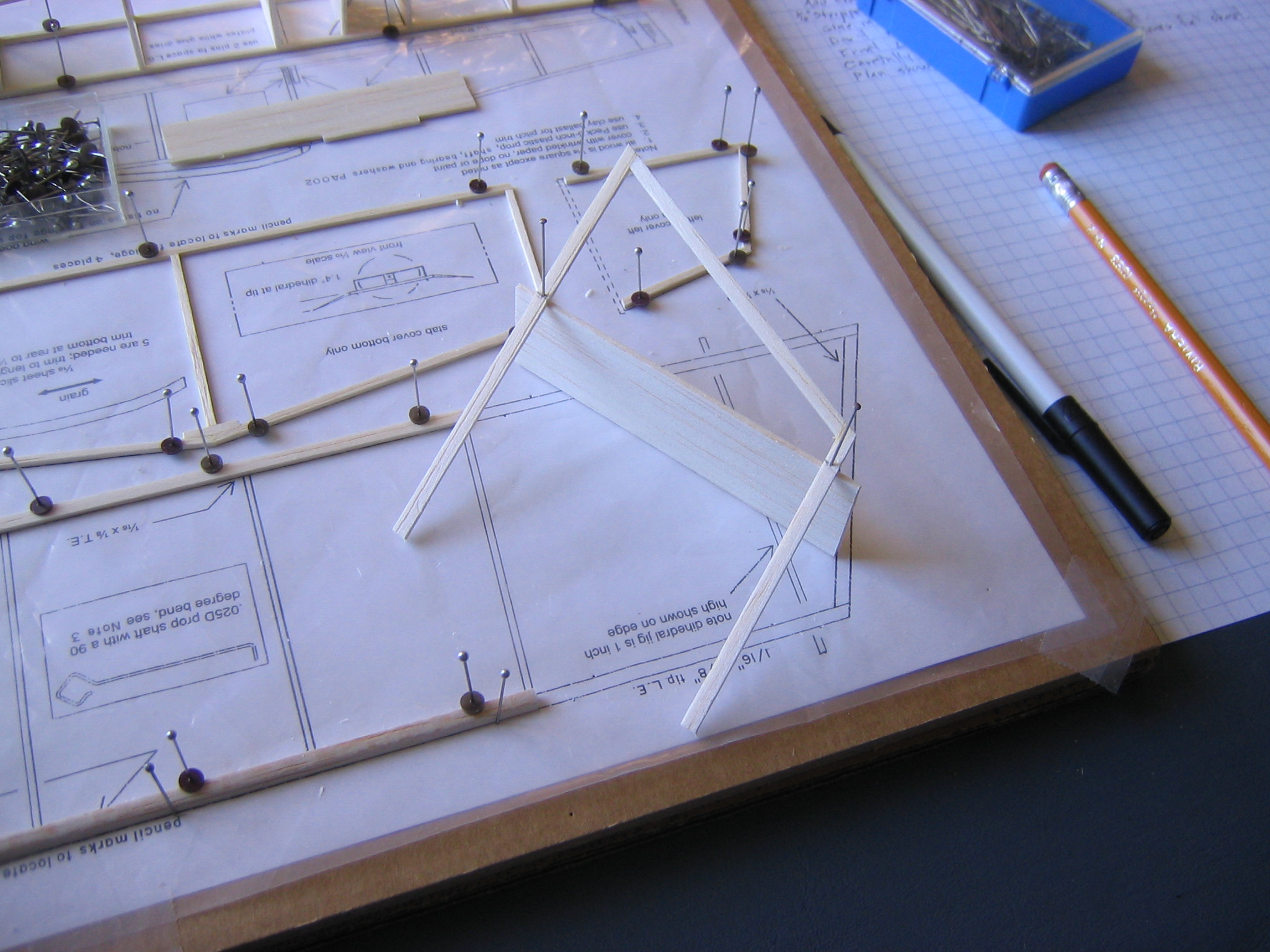
Remove the pins from the wingtips and separate the wingtips from the plastic cover, but leave the center panel pinned down. Pin the 1″ x 3 ½” dihedral jigs to the plan on the locations shown, using two pins each, one from each side at a 45 degree angle. It is important that the bottom edge be flat on the building board. Put the wingtips back in place, propped up on the dihedral jigs. Lightly pencil mark the locations on the wingtip outlines where they lie on the dihedral jigs. Push straight pins through the wingtip leading and trailing edge, into the dihedral jig. Carefully remove the pins holding the dihedral jigs to the board.
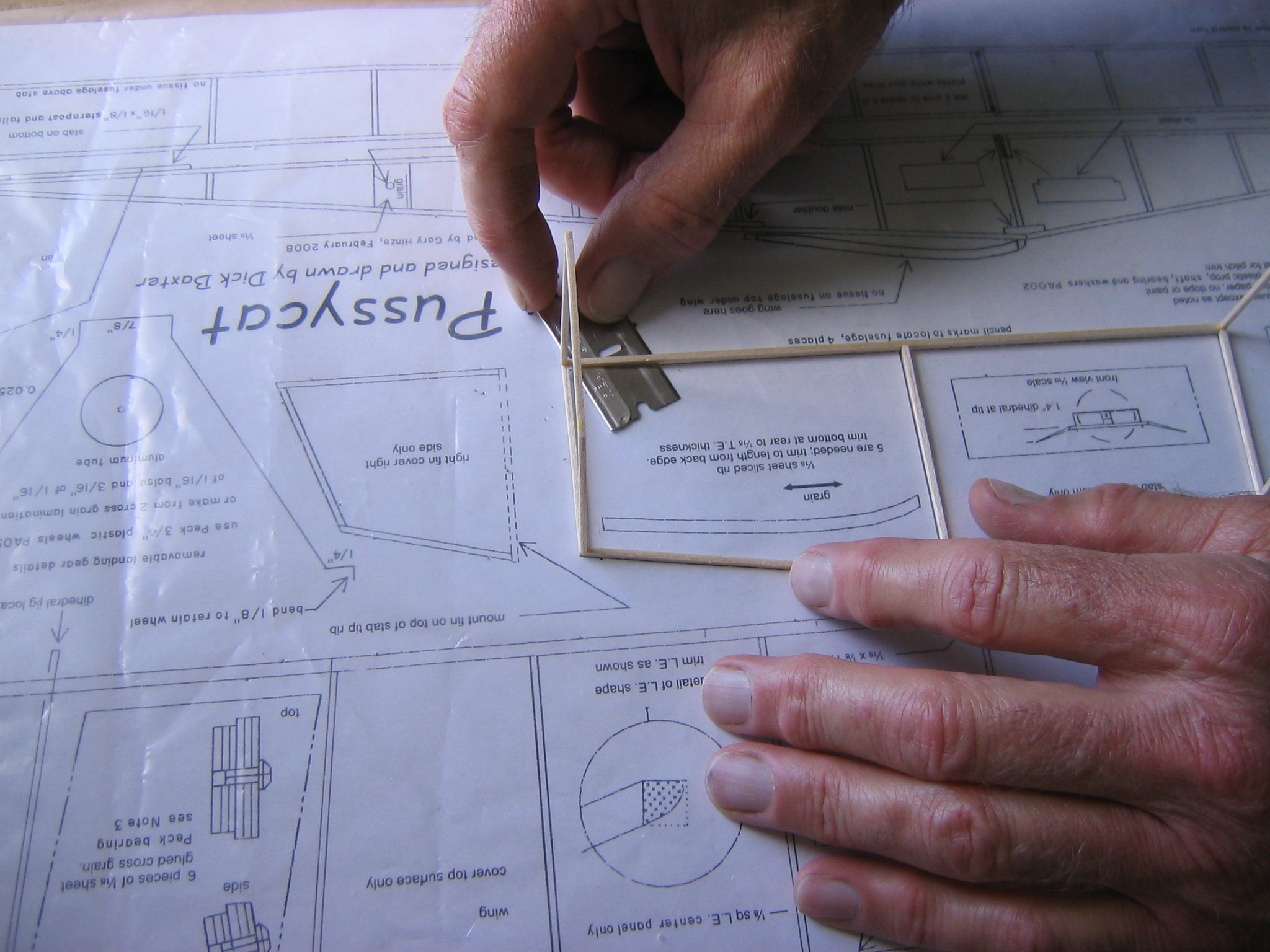
Hold the leading edge between the fingers of one hand while gently sanding the end with the sanding block. The edge of the sanding block is held flat to the table. The sandpaper face is kept aligned with both ends of the wingtip spars.
Sand gently with many easy sweeps of the sandpaper. Check the progress of the sanding from time to time. At first the top corner will be sanded off. Gradually the sanded face will expand downward. Stop sanding just as it reaches the bottom edge. Do the same with all four wingtip ends.
Now put glue on each of the wingtip spar ends and on the ends of the center panel spars and slide the wingtips against the center panel. Line them up very carefully so the leading and trailing edges are straight with no offset and the ends of the tip spars are on the board.
Pin or weigh the dihedral jigs down so they are also flat on the board. Use just enough weight to hold them flat and be careful to not bend the wingtip spars with too much weight.
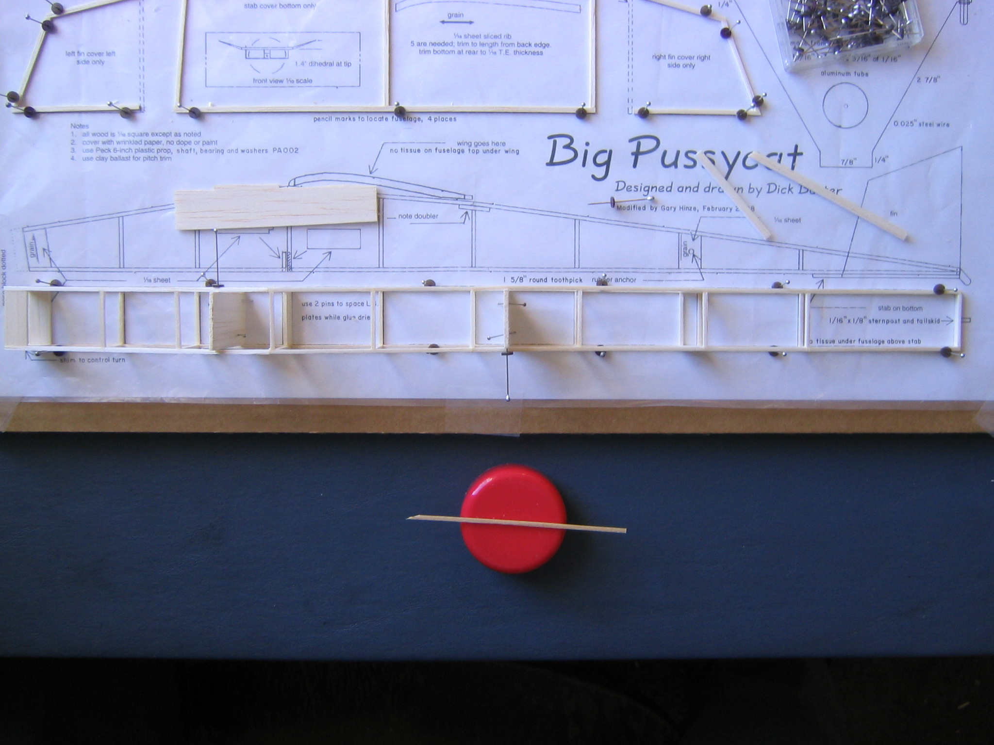
Join the Fuselage Sides
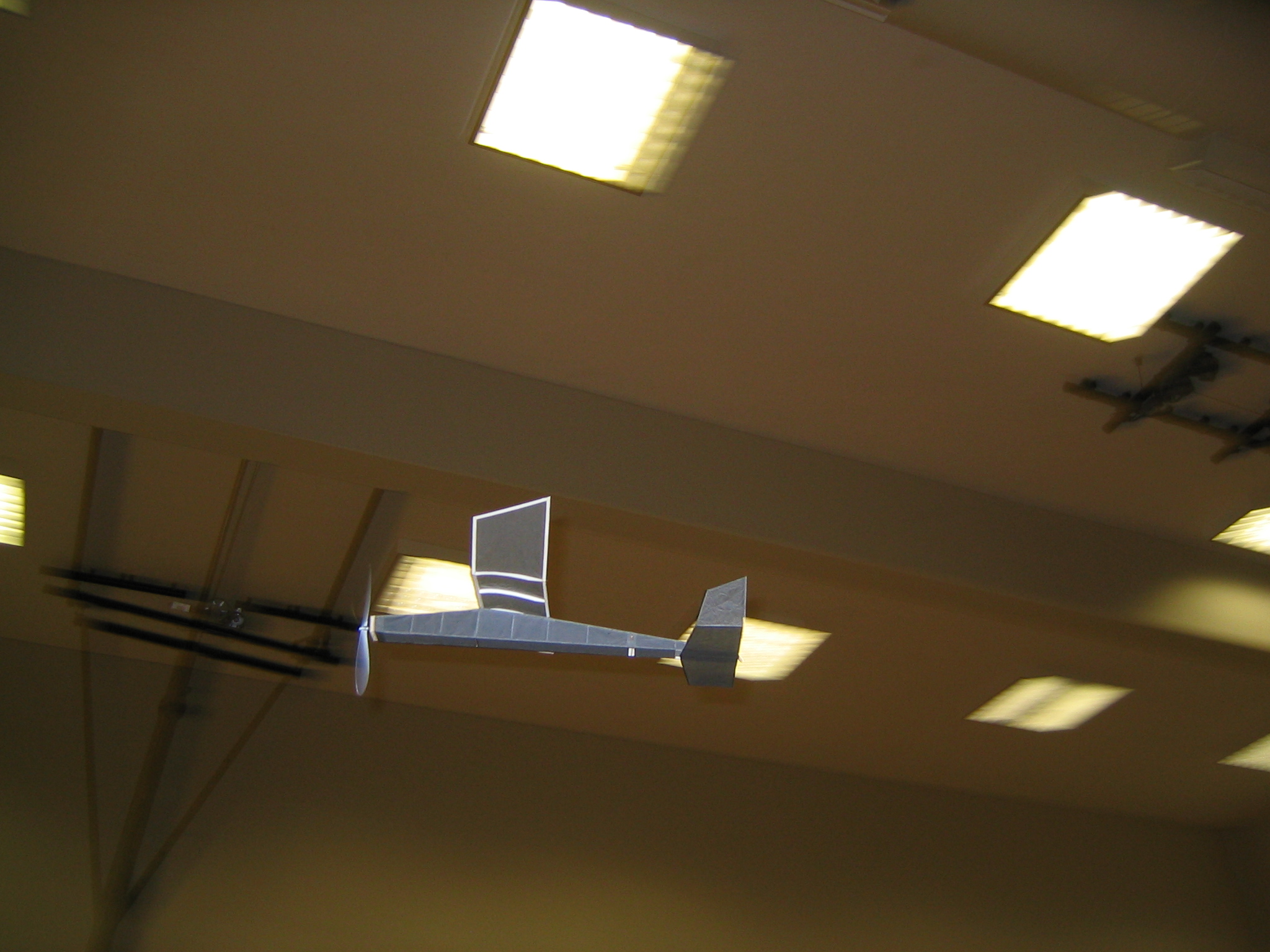
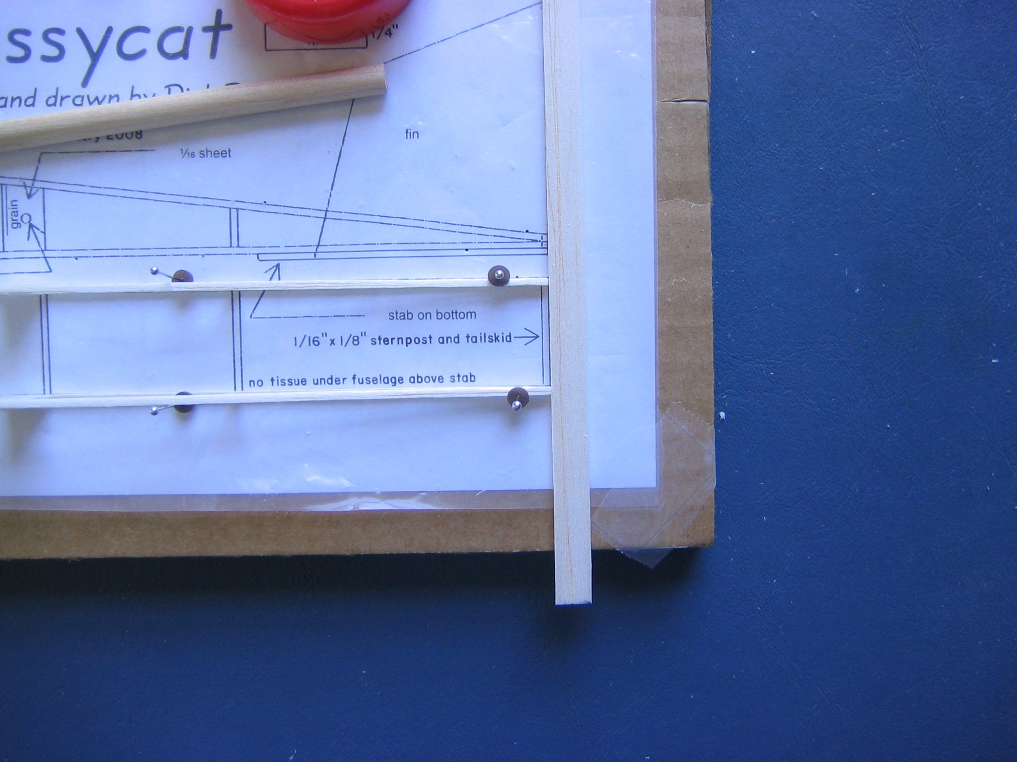
The fuselage sides are joined by 21 cross pieces, all 7/8″ long, made from 1/16″ stripwood of various widths. The two at the nose are 3/8″ wide. The sternpost is 1/8″ high. The one at the back of the landing gear box is 5/16″ high. There are 16 made from 1/16″ square strip, including one at the front bottom corner of the motor anchor plate. This will allow us to cut a small window in the belly between the two 1/16″ square cross pieces so we can see to get the peg through the motor. You can see this hole in the close up picture of the completed Big Pussycat flying.
All the crosspieces should be cut square on both ends. I did this by sanding one end square on the sanding jig, cutting the pieces, several at a time, with the razor blade, a tad long,
then sanding the other end on the sanding jig, placing them against the stop with the squared
ends against the fence so they extend across the 7/8″ face of the jig.
ends against the fence so they extend across the 7/8″ face of the jig.
This makes them all exactly the same 7/8″ length. It was possible to sand several at a time this way. See the post on Tools where the use of the sanding jig is described. There are two 3/8″ wide nose plates, top and bottom, one 5/16″ back landing gear box side, one 1/16″ x 1/8″ sternpost and sixteen 1/16″ square pieces.
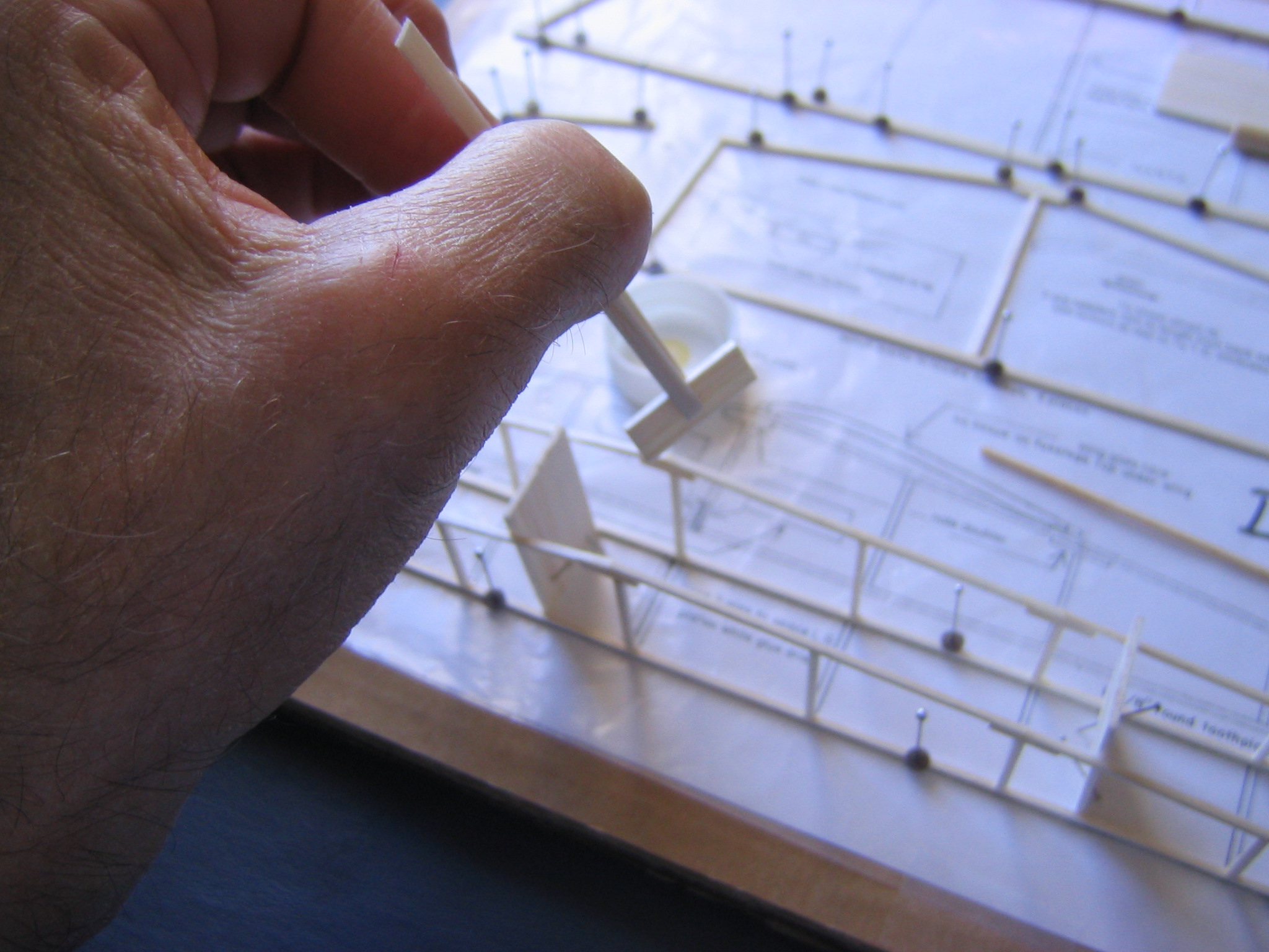
The front of the landing gear box is 5/16″ x 1″ with 1/16″ square notches cut in the lower corners to fit over the lower longerons. The notches are 7/8″ apart. These notches may be cut with the 1/16″ balsa stripper, or you can cut them out with the razor blade. Here a cut is made parallel with a long side, just pushing the edge 1/16″ past the edge of the blade.
Here a cut is made parallel with a short side. The piece is held vertical and pushed with the squared end of some scrap balsa.
The finished piece.
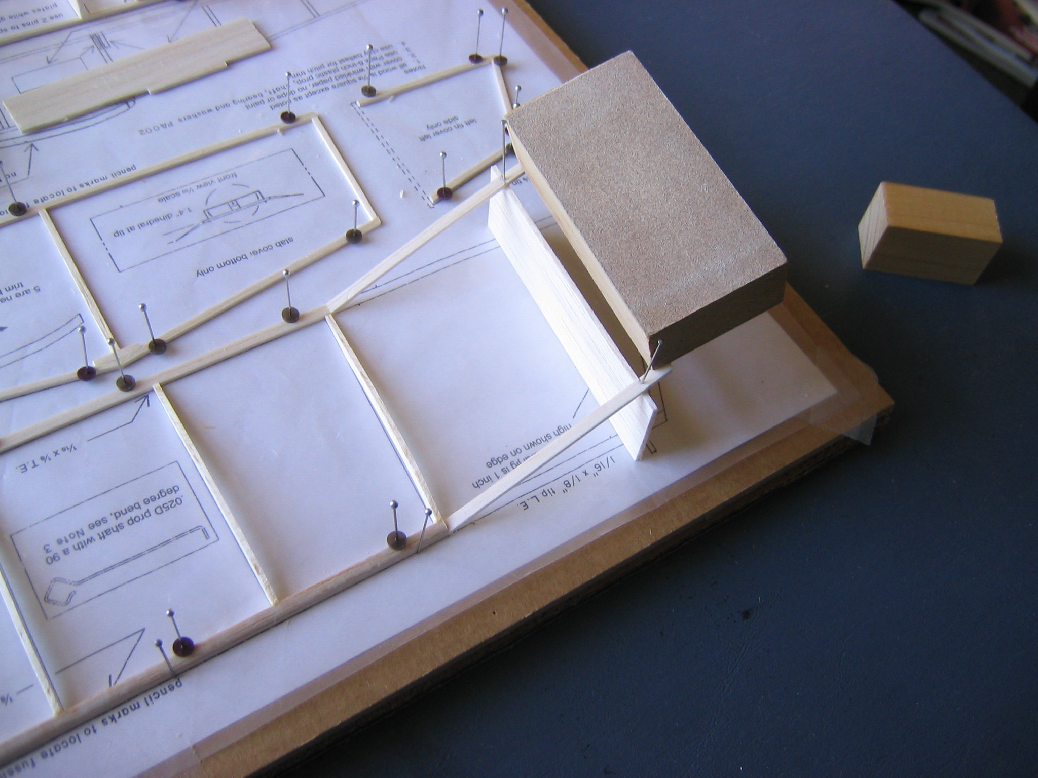
To get a square box fuselage it is necessary to hold the fuselage sides perpendicular to the building board. This can be done in two ways. One is to put 3/4″ x 7/8″ x 1 1/2″ pine blocks between the sides and pin the sides down to the board so they touch the pine blocks.
Another is to use the two 1/16″ x 7/8″ x 1 3/8″ fuselage jigs we cut out. These are pinned to the building board with two pins, pushed in from opposite sides at 45 degree angles so the ends of the jigs are perfectly flat on the board. The jigs should go straight across between the fuselage sides and fit exactly between the lines. A good place to put them is in the fuselage bays just ahead of and behind the wing location.
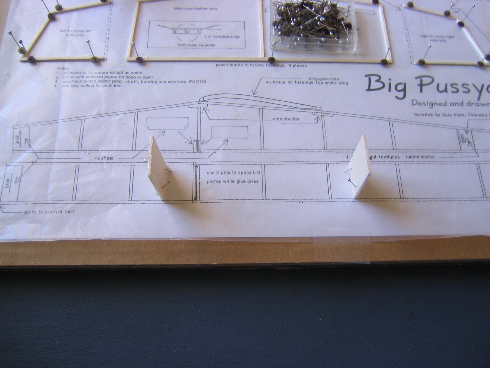
The fuselage sides are then pinned snugly down on the board and to the edges of the jigs. They are not glued to the jigs.
Be careful when doing this not to break the longerons. It is safest to use the dowel pin pusher. Make sure the two back ends are exactly aligned with the drawing, place a stick or block across them to make sure they both end on the same line. This is important to getting a square fuselage.
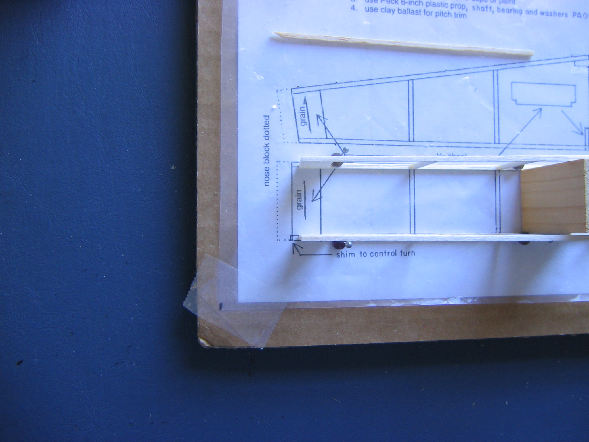
Note that there will be a slight gap between the front ends of the bottom longerons and the drawing. This is because the drawing shows the top of the fuselage, which sticks out beyond the bottom. Therefore, do not try to align the fuselage sides with the drawing at the front end.
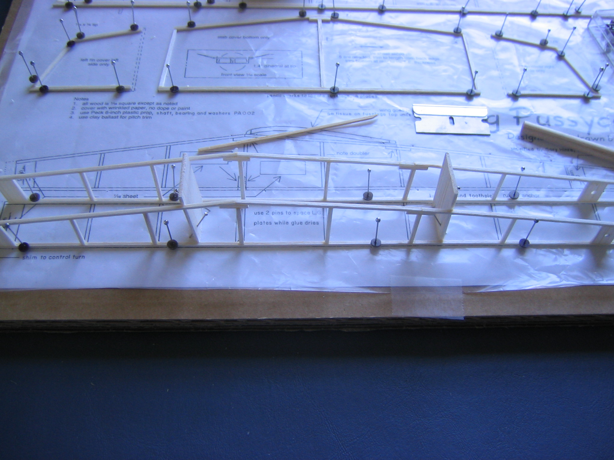
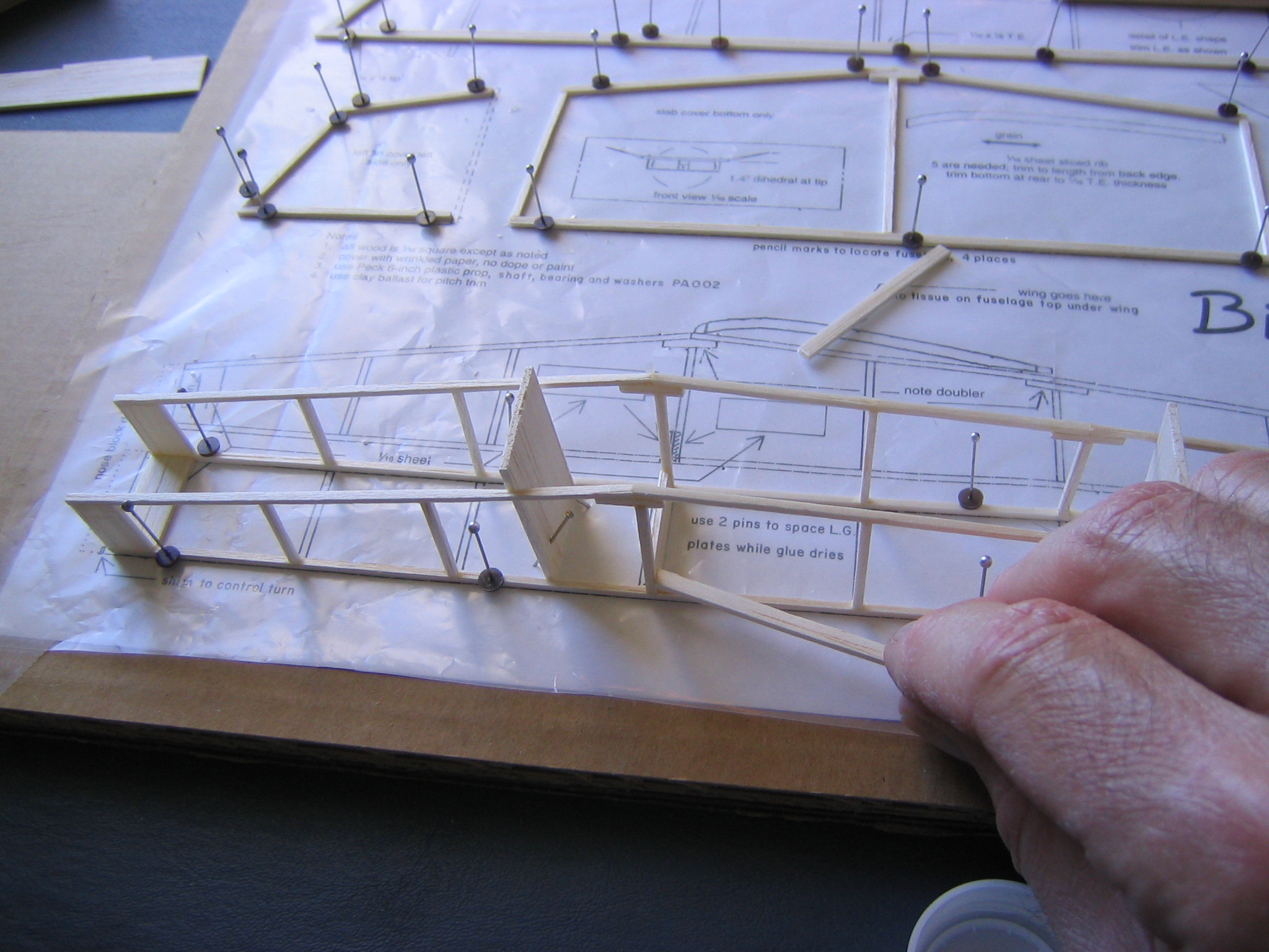
Now glue between the bottom longerons, in order, the nose plate, the sternpost, the rear landing gear box plate, using tweezers or a couple of sticks, as shown.
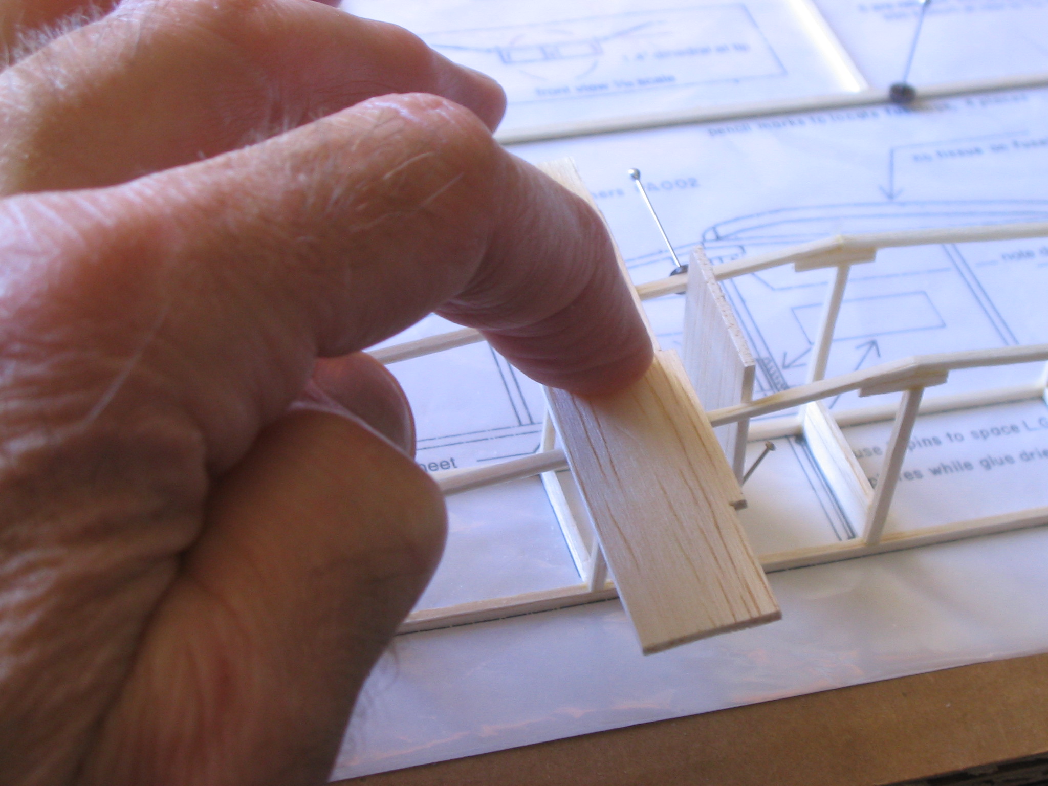
Make sure it is straight up and down and straight across,
Check that everything is square and aligned properly before the glue hardens. Then glue in the 1/16″ square crosspieces. Let the glue dry. Now put in the top nose plate and the two crosspieces at the wing leading and trailing edge positions. These must be flush with the top of the longeron. This is done by putting them in so they stick up slightly,
very gently squeezing the uprights together if necessary, then pressing the crosspieces down with a piece of balsa.
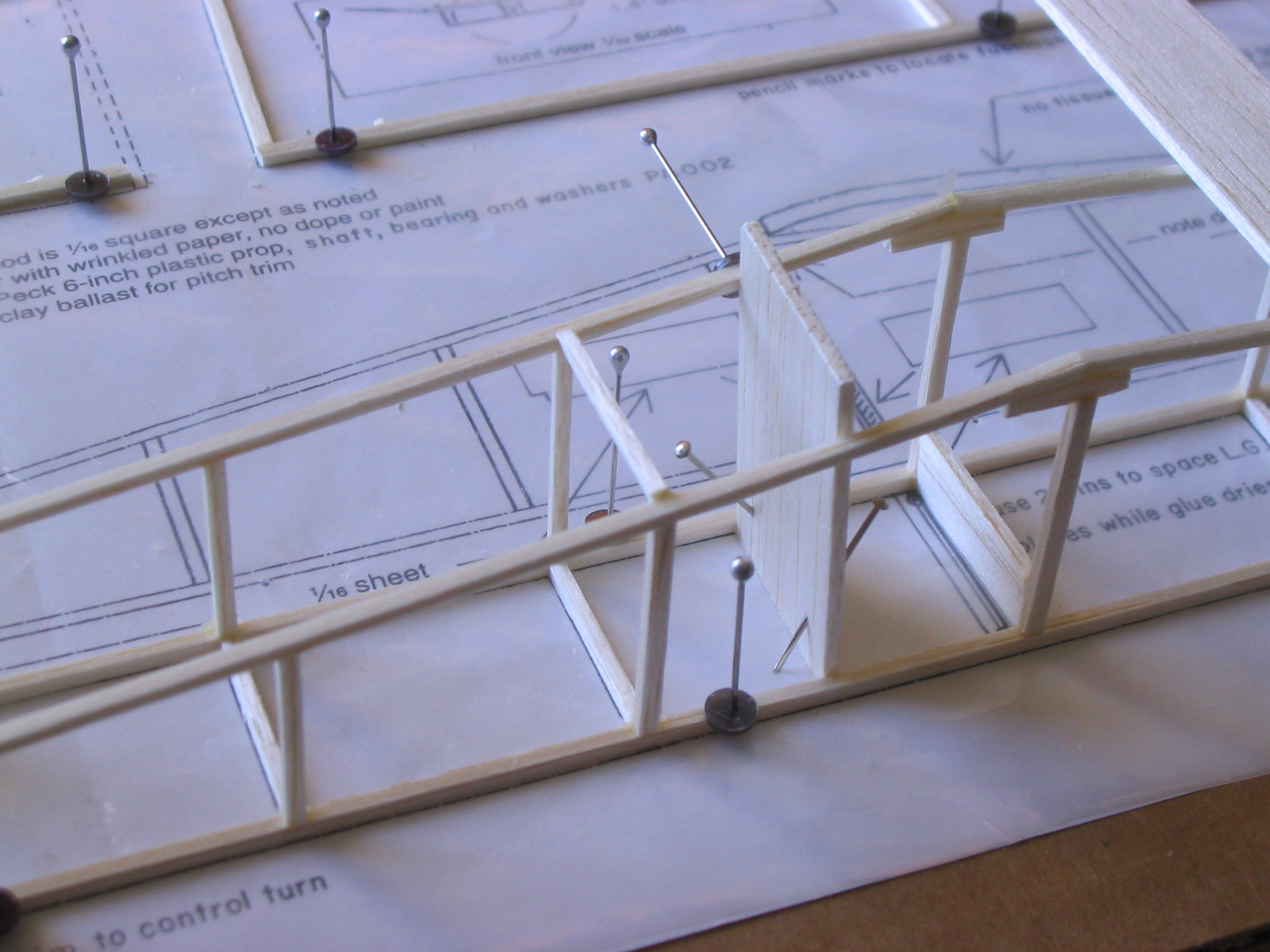
Check that it is properly aligned and flush with the outside surface. Let the glue dry. You can see in the picture the rear plate of the landing gear box, glued between the uprights at the wing leading edge. You can also see that I put a pin clamp into the jig on the far side to hold the fuselage side to the jig.
Alternatively, you can unpin the fuselage, turn it upside down and pin it back down, pressing the crosspieces down to the board, as before. There are three sections to the top of the fuselage, so you will be pinning it down three times. The upper longerons are a little longer than the lower longerons, so the crosspiece spacing will not be exactly as shown on the plans. Instead of placing the crosspieces as spaced on the plan, place them to correspond to the tops of the uprights. It is easier to press them down flat to the board than having to squeeze the fuselage sides together while pressing them down with a scrap of balsa.
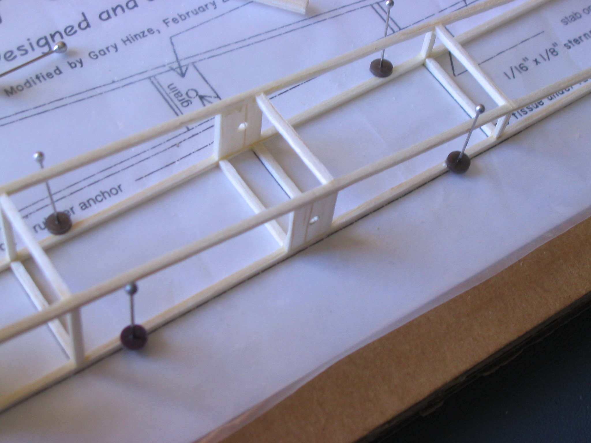
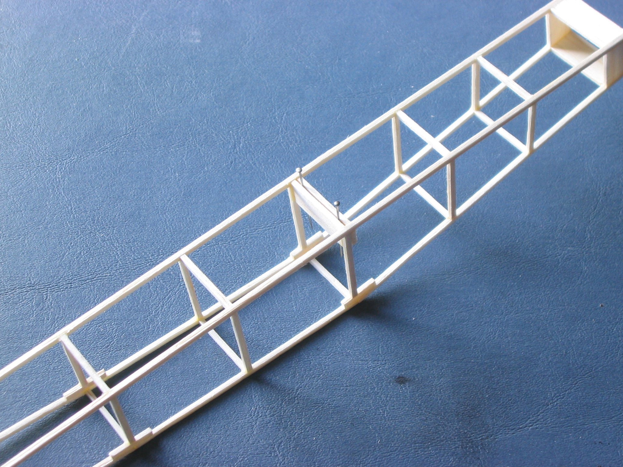
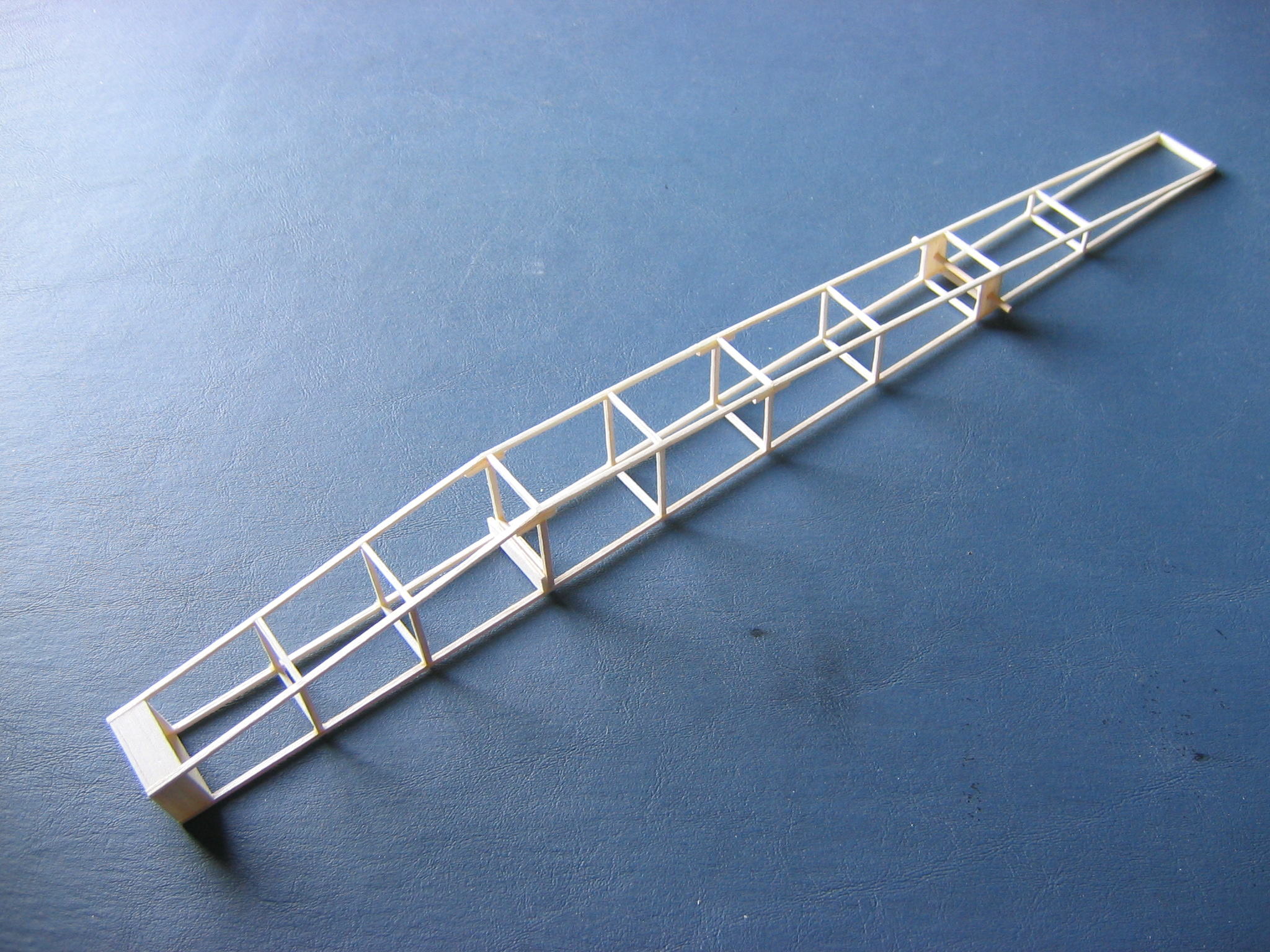
This shows the finished fuselage structure.
Here is a close up of the opening to view the motor and motor peg during installation of the motor. The crosspiece at the bottom left of the peg anchor plates is not shown on the original plan.
Once the glue is dry, unpin everything and remove the fuselage and jigs from the board.
The front of the landing gear box must be glued to the two bottom longerons just ahead of the rear plate of the landing gear box, that was glued between the uprights below the wing leading edge. Two pins are placed between these plates to space them apart as the glue dries. The wire landing gear will then be a snug friction fit between these plates.
This shows the completed fuselage with the motor peg installed in the anchor plates.
Click HERE to go to Chapter 6.
One thought on “Big Pussycat Chapter 5 – Assembling the Fuselage and Tail”