So far we have made a lot of little wood parts. In this chapter we will begin to see an airplane emerging from those bits.
Build Two Fuselage Sides
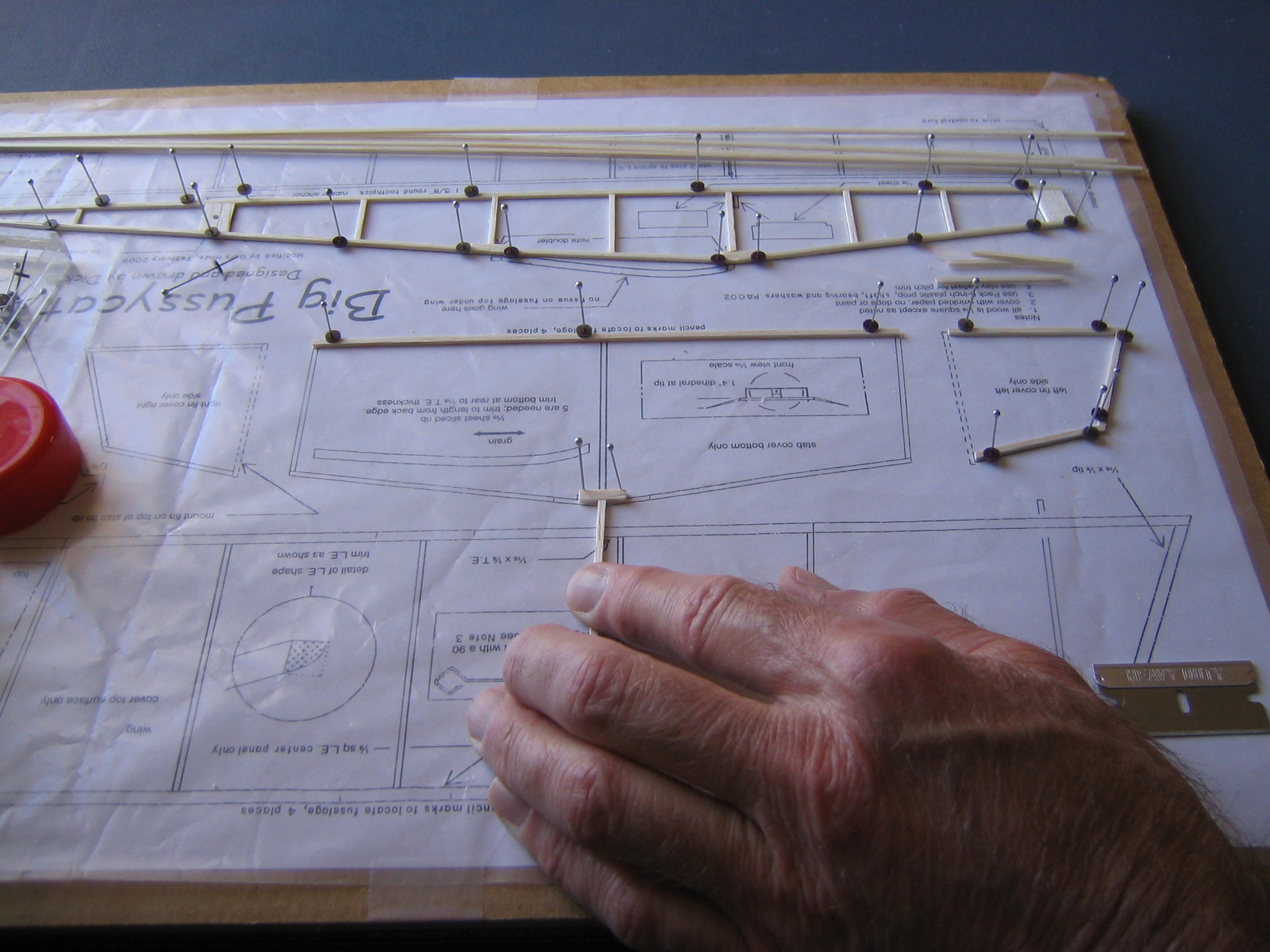
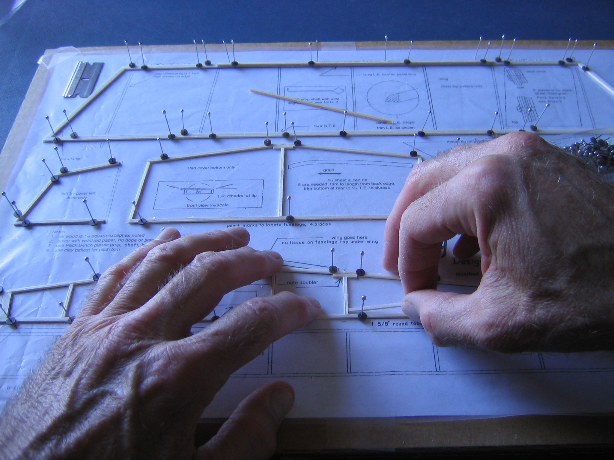
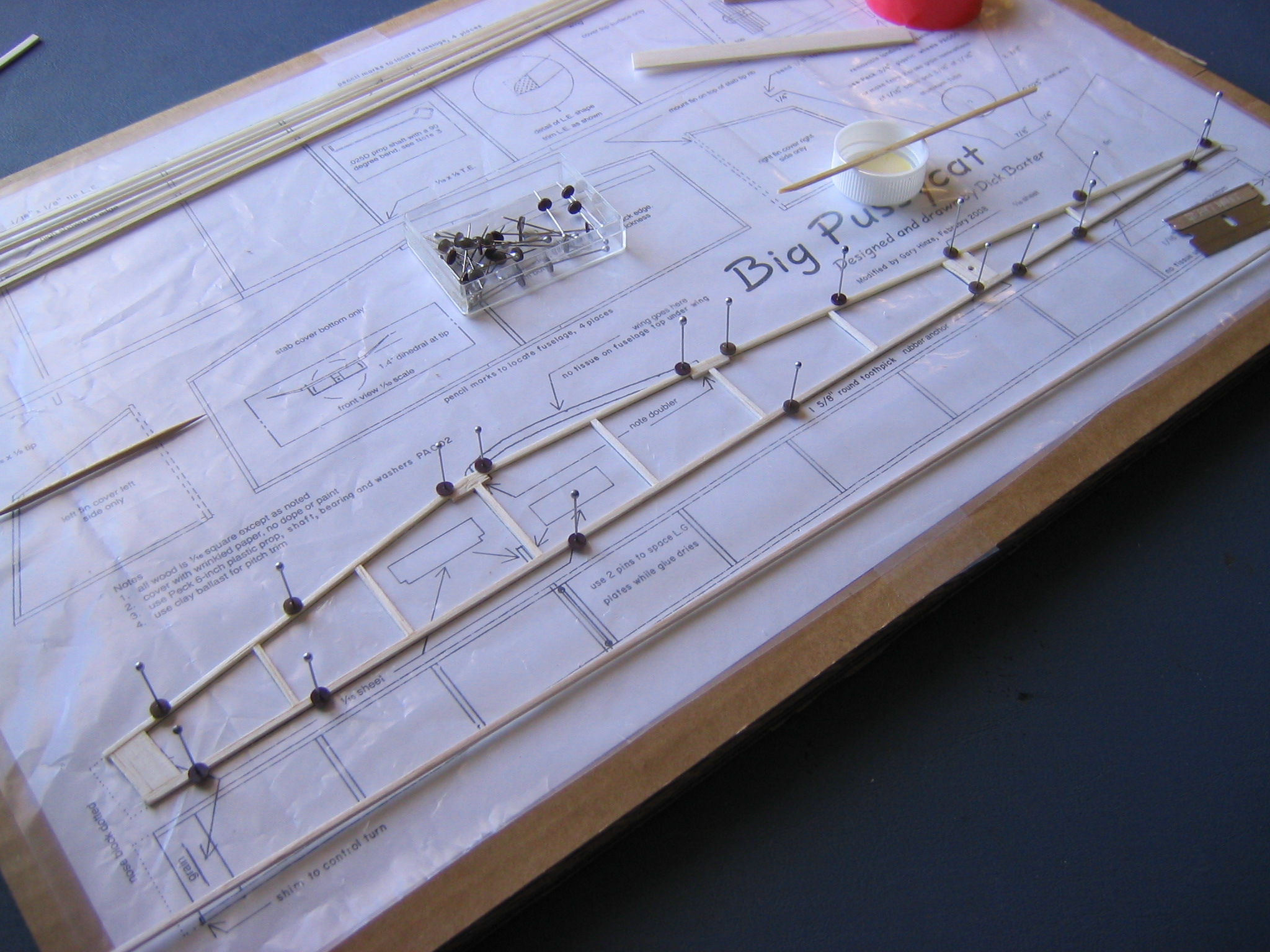
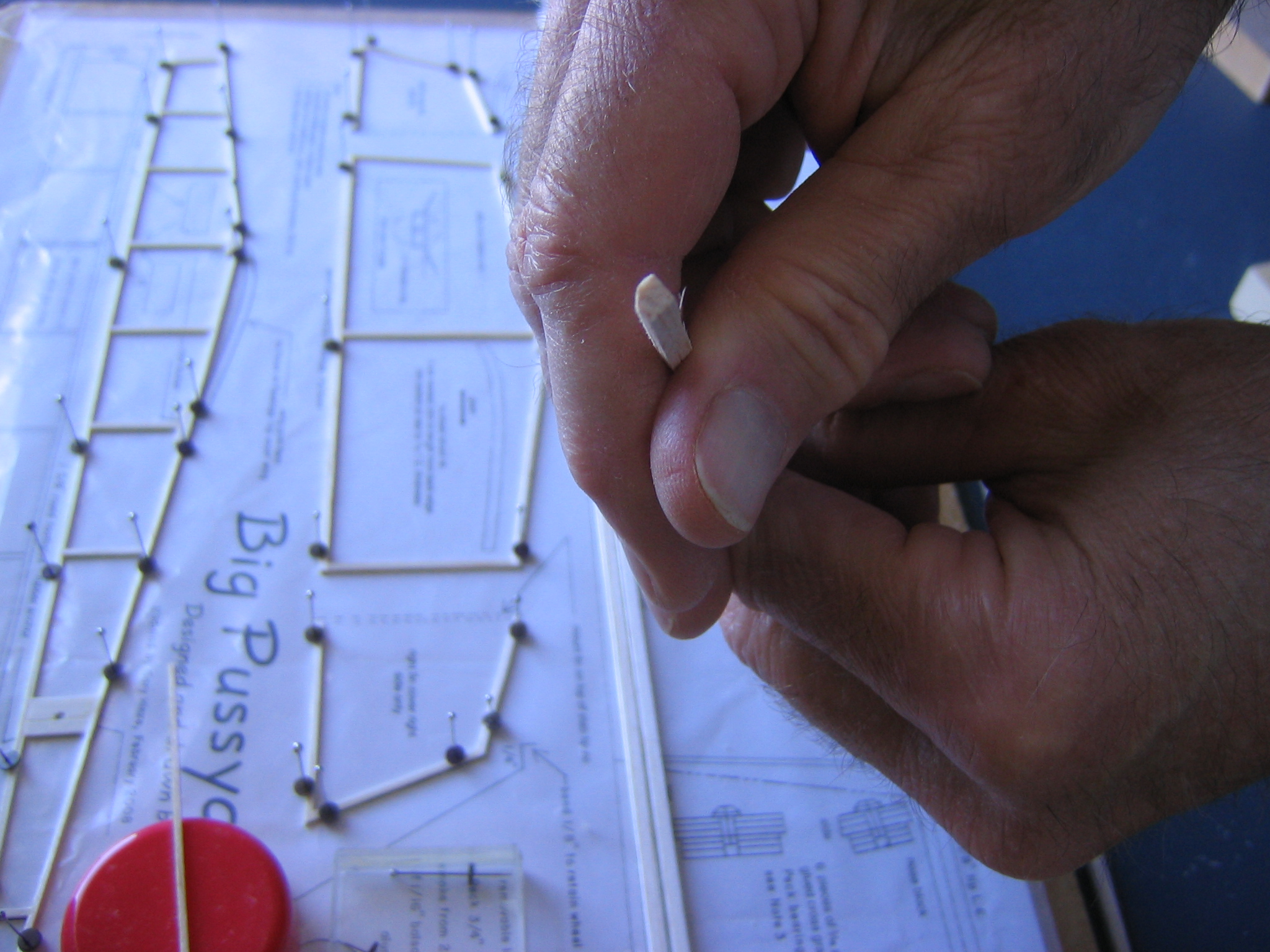
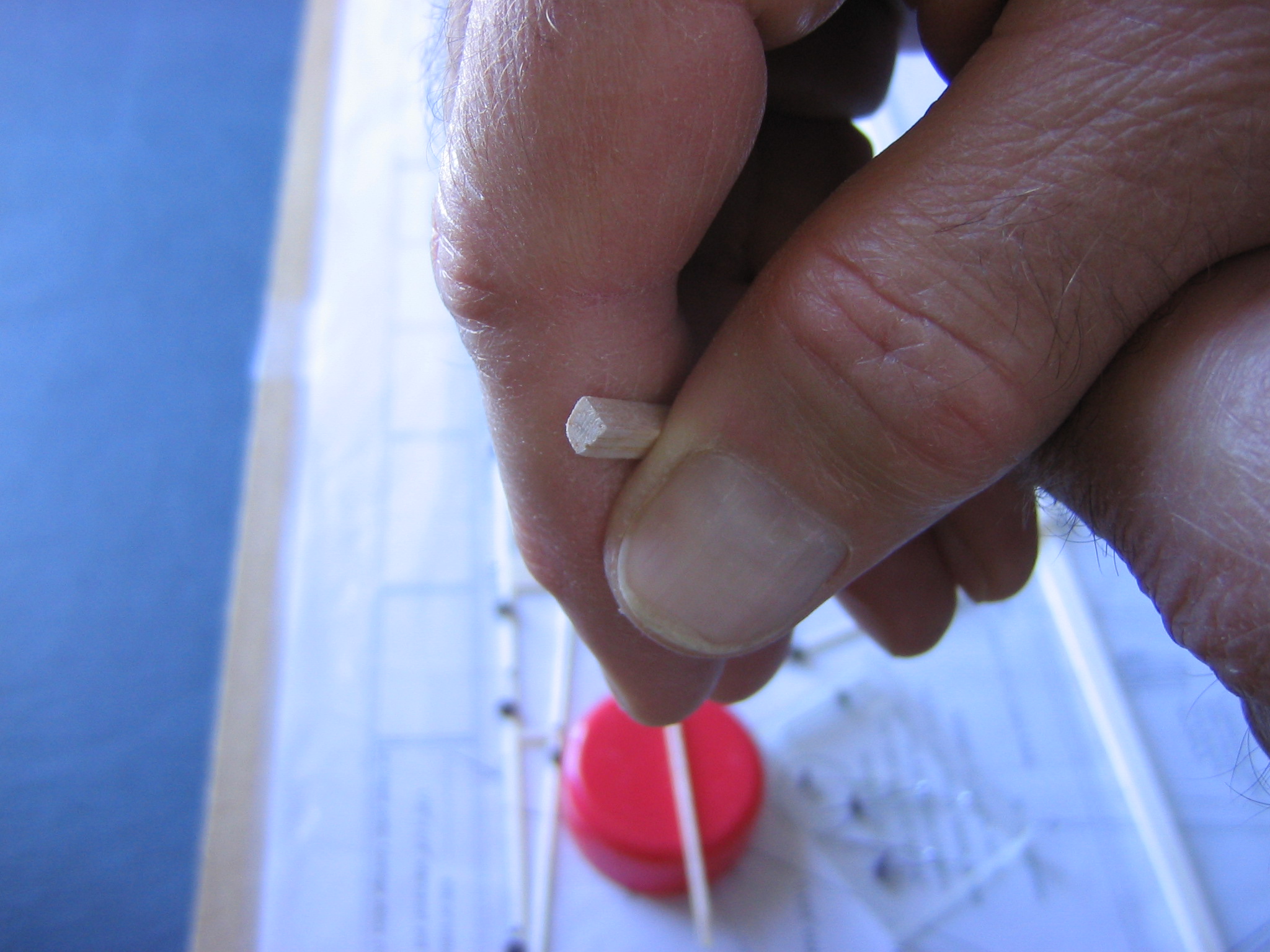
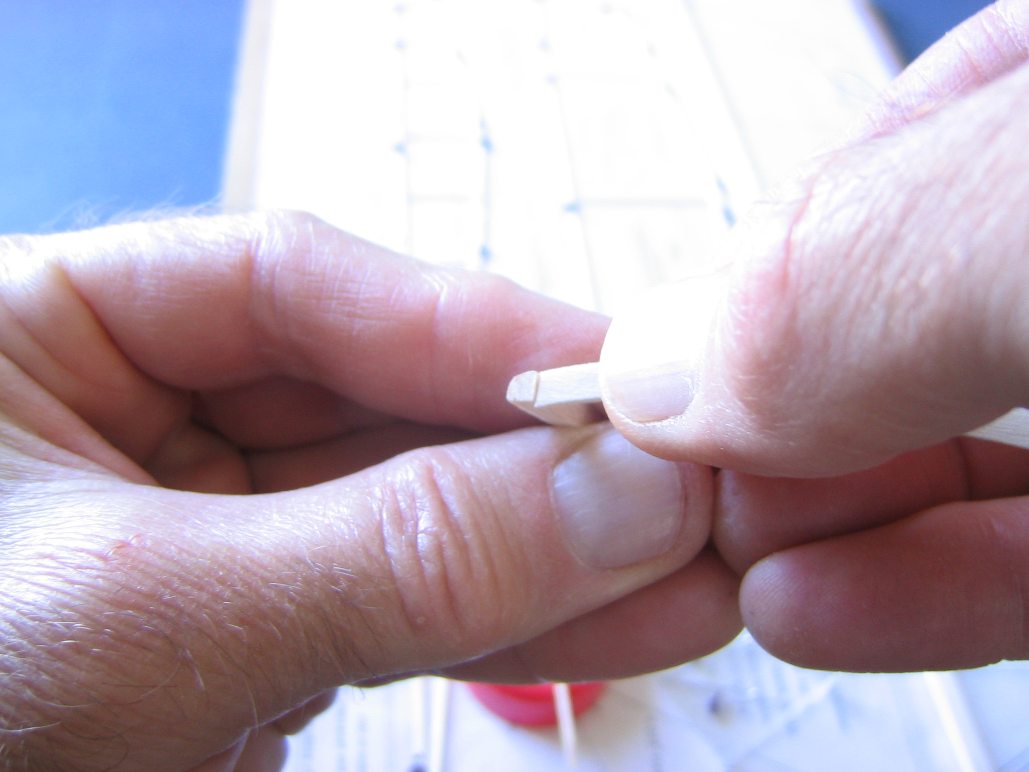
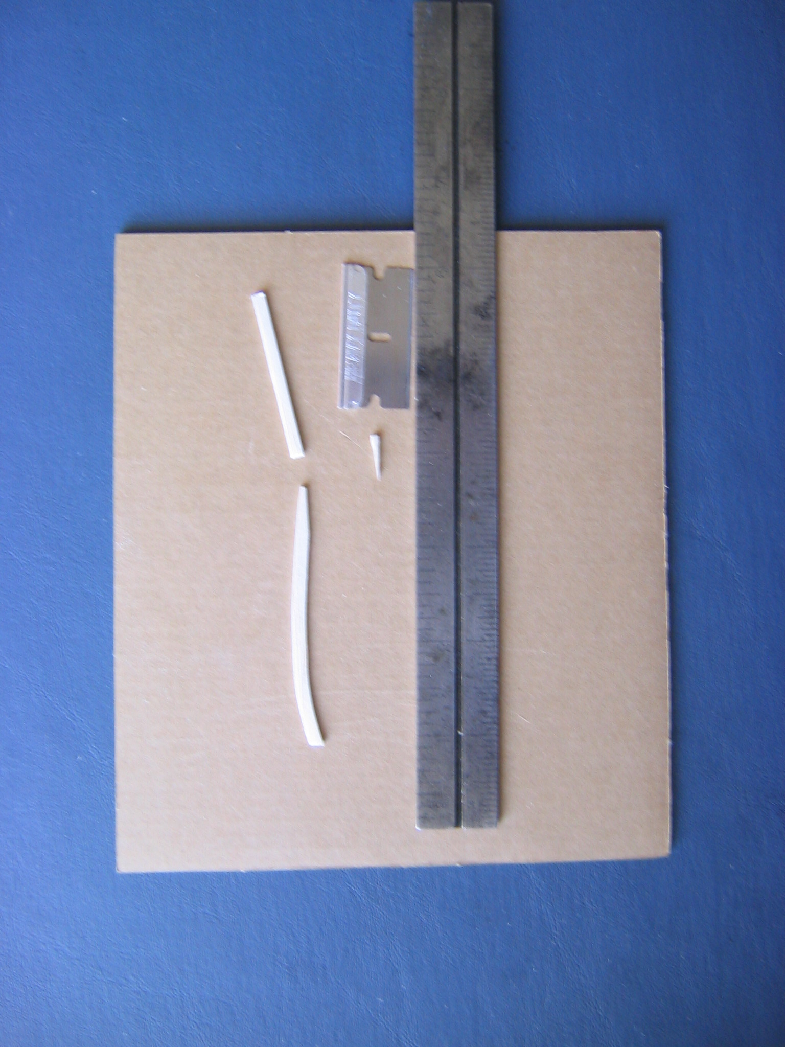
Build them one at a time, working on other things while the glue dries on the first one. Do not build anything over the top view, build them over the side view. The longerons are the long pieces that run the entire length of the fuselage, from the nose to the tail. The bottom and top longerons come together at a small angle at the back and they are glued together. The bottom longeron is one piece. The top longeron is made from three pieces. There is a small change of direction in the top longeron just under the wing trailing edge. The purpose of the doublers on the longerons at the wing leading and trailing edges is to strengthen the longerons at these break points where the wing attaches to the fuselage. The gusset under the wing leading edge location is made from a half inch length of 1/16″ x 1/8″. It should be made first, before the longerons are pinned down. Push two pins into the drawing on the side of the gusset away from the longerons. Place the ½” piece of wood against these two pins, line the ends up with the ends of the drawing, and hold the wood against the pins with a short stick. (These pictures show the making of the gusset plate for the tailplane, done in the same way.)
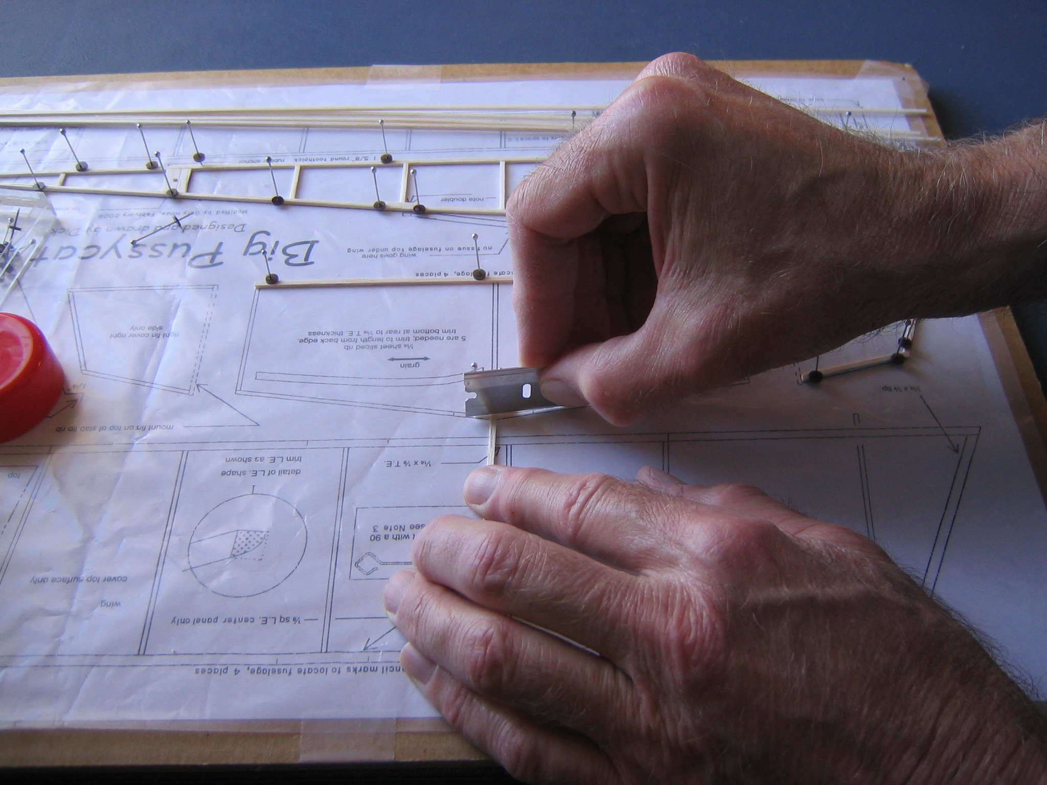
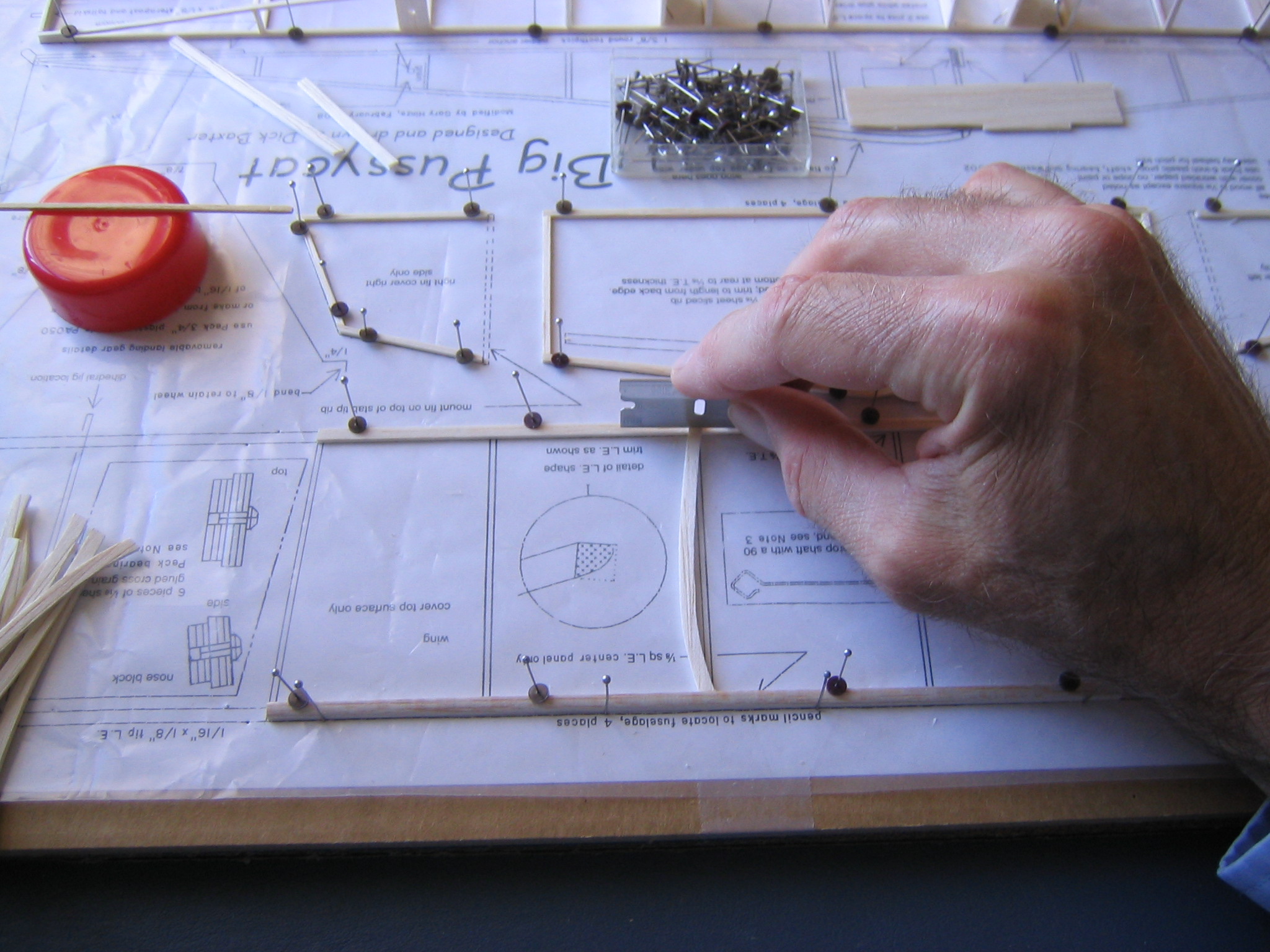
Place one end of the razor blade on the line of the longeron and place the other end across the gusset plate. Press down to crease the piece of wood. Do the other side in the same way. You can cut straight down with the razor blade, or you can put the plate on the sanding jig and sand square faces.
The gusset under the wing trailing edge location can be made from 1/16″ square in the same way, or by shaping the slight angle with some light strokes of sand paper to get good fit. Square the back end of the lower longeron, all one piece of 1/16″ square strip, hold it in place and mark the front end, at the angle shown on the plan, cut slightly long and sand it on the jig to the marked line. Pin it to the plan, carefully aligning the back end with the line on the drawing. The top longeron is in three pieces. There is a break under the trailing edge of the wing. Mark each end at the angle shown on the plan, cut slightly long and sand to the line on the sanding jig. The bottom end of each of the uprights can be sanded square with the jig. This will make stronger joints. The top ends may be marked with the razor and sanded to the marked line. You can get good, flat top ends by marking the cut with the razor, cutting a bit beyond the mark, placing the piece at an angle on the sanding jig with the razor mark aligned with the edge of the block and sanding it down to the line.
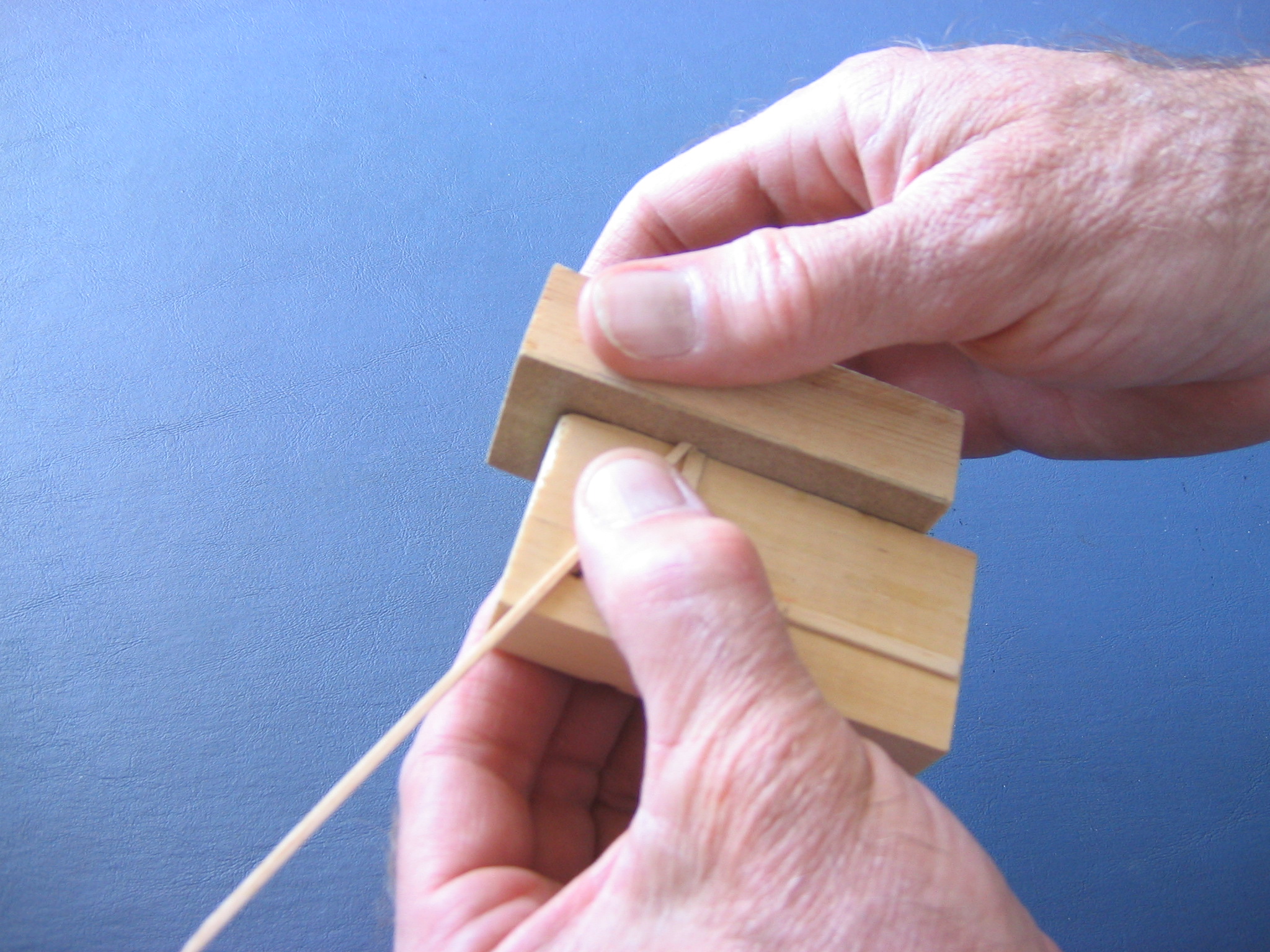
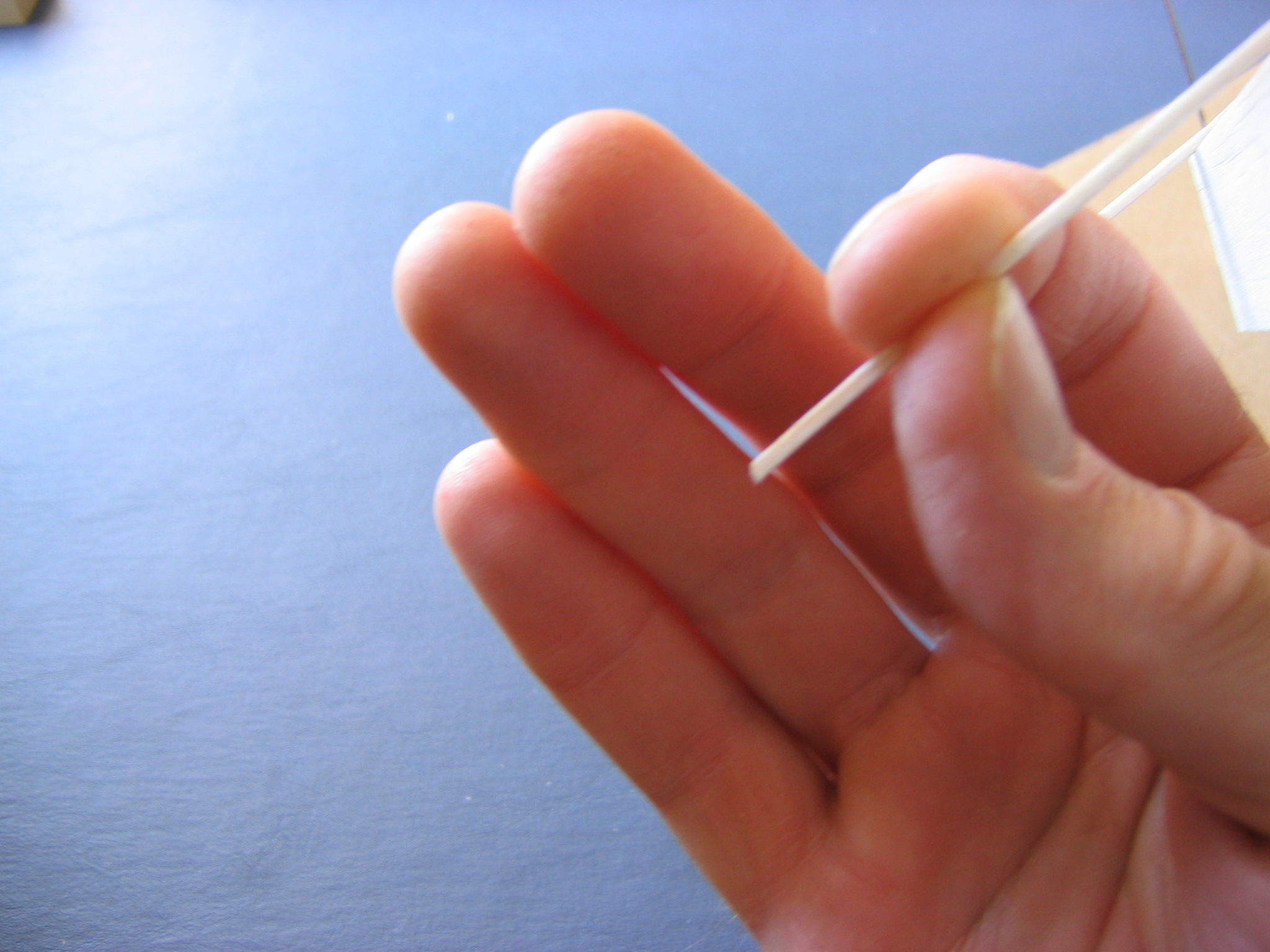
Hold the piece close to the end being sanded and sand lightly. Take your time, this isn’t a race. Put a drop of glue on each end and touch each end to the longeron to get glue there. These pieces can be pushed into exact place with a stick.
Press them flat to the board with your finger. The side nose plate is made from the 3/8″ wide strip, with the top and bottom edges being marked and sanded in the usual way. The front of this must be exactly on the line, since it controlls the thrustline of the propeller. The peg plate is made from the 3/8″ strip, as explained in the previous chapter, and glued in place between the top and bottom longerons. Here is a completed fuselage side. Work on something else until the glue dries, then come back to make the second side.
Build the Tailplane and Fin Frames
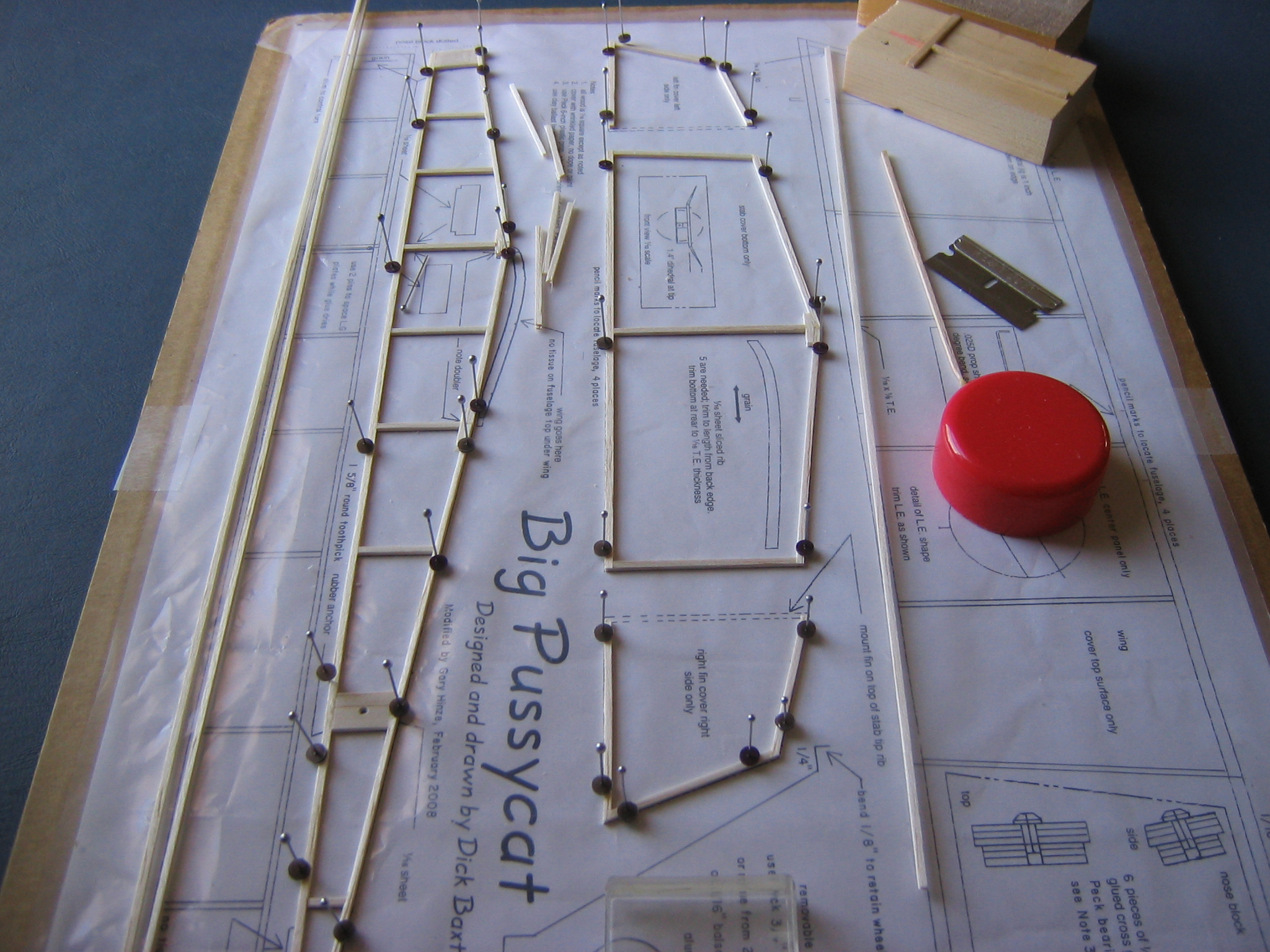
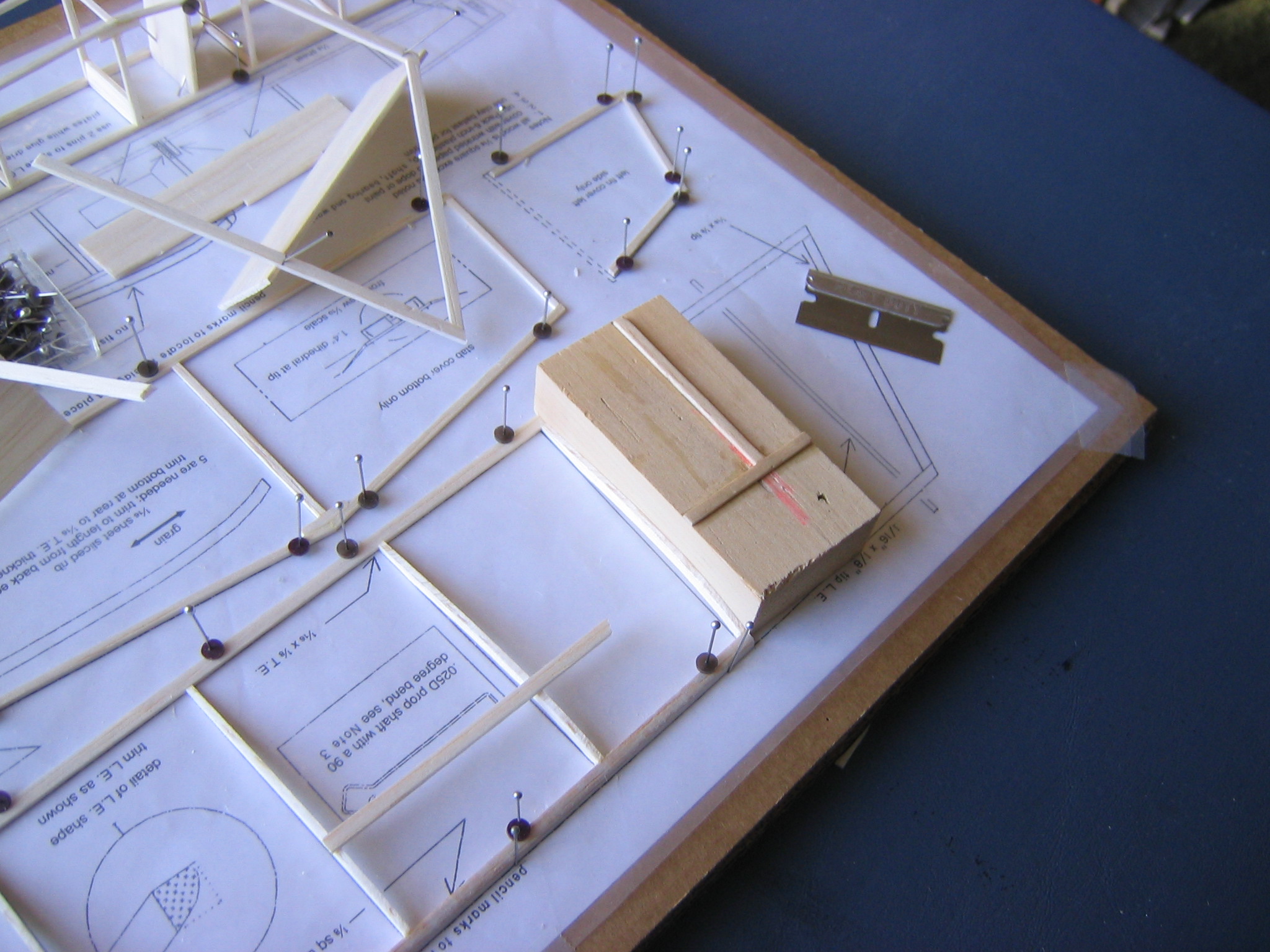
Turn the board around to make it easier to get to the work area. The gusset inside the front point of the tailplane is made from a ½” length of 1/16″ x 1/8″ as shown above. Everything else is made from 1/16″ square strip, as written on the plan. Note that the fin frames consist of three sticks, the fourth being shown as dashed lines. The dashed lines represent the tip tailplane ribs, to which the fins will be glued later. For now, let the glue dry, we will glue the fins to the tailplane later. Make light pencil marks on the leading and trailing edges of the tailplane to show the fuselage location, as shown on the plan. Here is the finished work.
Build the Wing
The wood dimensions for the wing parts are shown on the plan. The leading edge of the central panel is 1/8″ square. The trailing edge of the central panel is 1/16″ x 1/8″. The leading edge, tip and trailing edge of the wingtips is 1/16″ x 1/8″.
Start by cutting out the wing leading edge, marking with the razor, cutting a bit long and sanding the ends to the correct angle, as was done for the fuselage uprights.
Sand the curve in the leading edge, as shown on the plans. There is a lot of sanding dust produced in this step, so this would be a good time to put on your dust mask. The curved leading edge is sanded from the square cross section shown here,
starting with the coarse sandpaper, in steps, by first sanding the top front corner off the 1/8″ stick, after marking it with a pencil to be sure you sand the right corner off!
This produces two new edges and a new face, forming a cut diamond shaped cross section.
Sand each of the new edges in turn, then round the surfaces to match the cross section shown on the plan. Note that the front curve comes down perpendicular to the bottom surface while the top curve ends in a slant that conforms to the slope of the top of the rib.
Place a rib against the back of the leading edge to judge the angle and get a smooth curve.
Finish with the fine sandpaper. Remember to put the curved edge of the 1/8″ square leading edge up and forward, as it shows in the side view of the wing, when you pin it down. The flat surfaces go down and behind. Cut and pin down the center part of the trailing edge. Note that the ends are cut at an angle, corresponding to the angle cut in the center stick, forming the angled dihedral break line. The ribs are a little long and must be cut to fit, place the leading end of the rib against the back of the leading edge spar and cut off from the trailing edge.
The angled ones on the ends will be longer than the ones that go straight across. The bottom of the ribs must be trimmed at the trailing edge to make the end 1/16″ high, as shown on the side view of the wing. A piece of 1/16″ wood may be used to locate the straight edge for cutting.
Glue the ribs between the spars and square them up with a couple blocks of wood. Hold them until the glue sets.
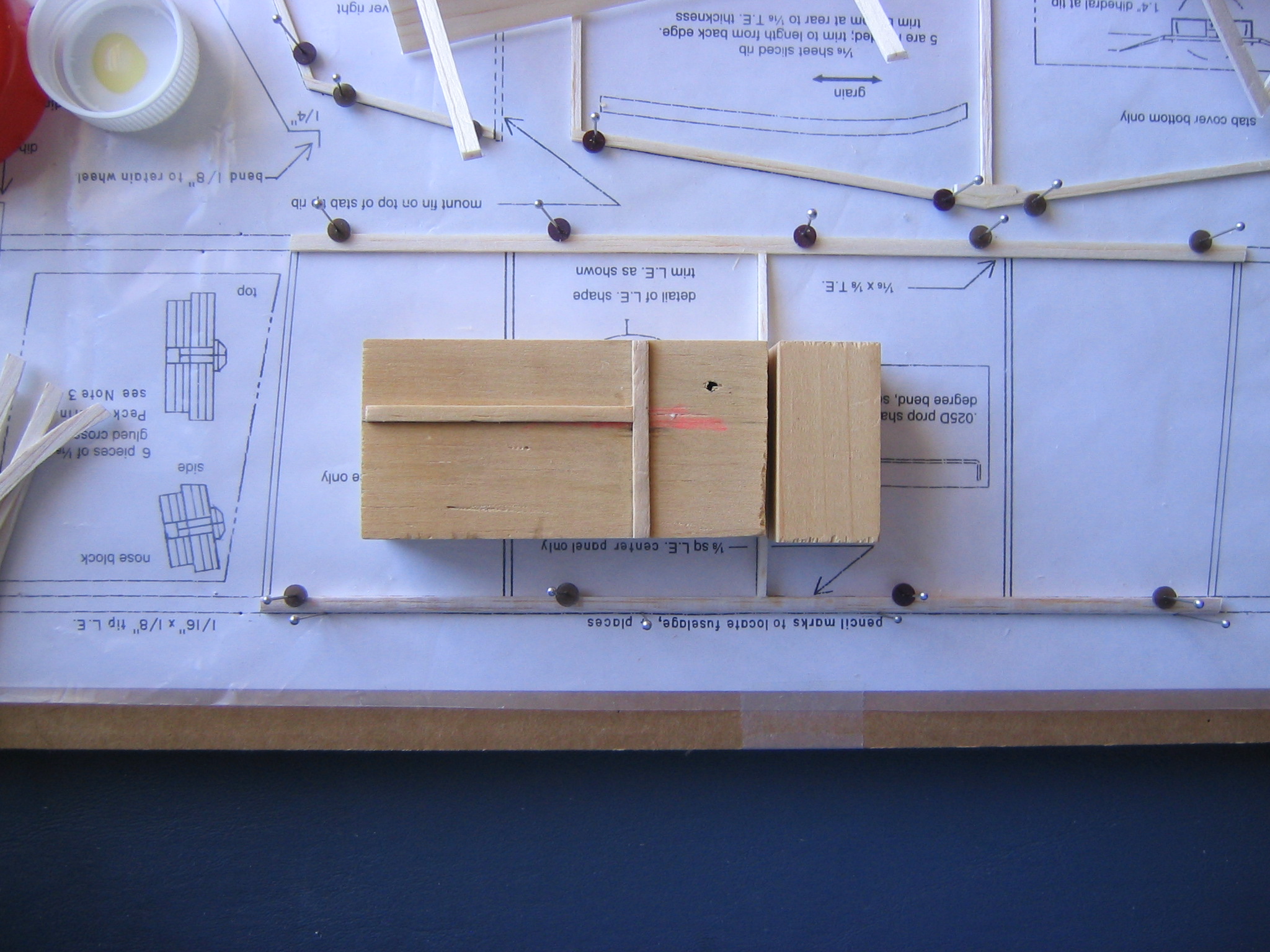
The end ribs are aligned to the ends of the spars with a block of wood.
Make light pencil marks on the leading and trailing edges of the center panel to show the fuselage location, as shown on the plan. Later these will be extended to the underside of the wing spars.
Cut and glue together the wingtip parts. They are separate units from the center panel. The bevel for the dihedral joints will be sanded into the ends of the wingtip spars later.
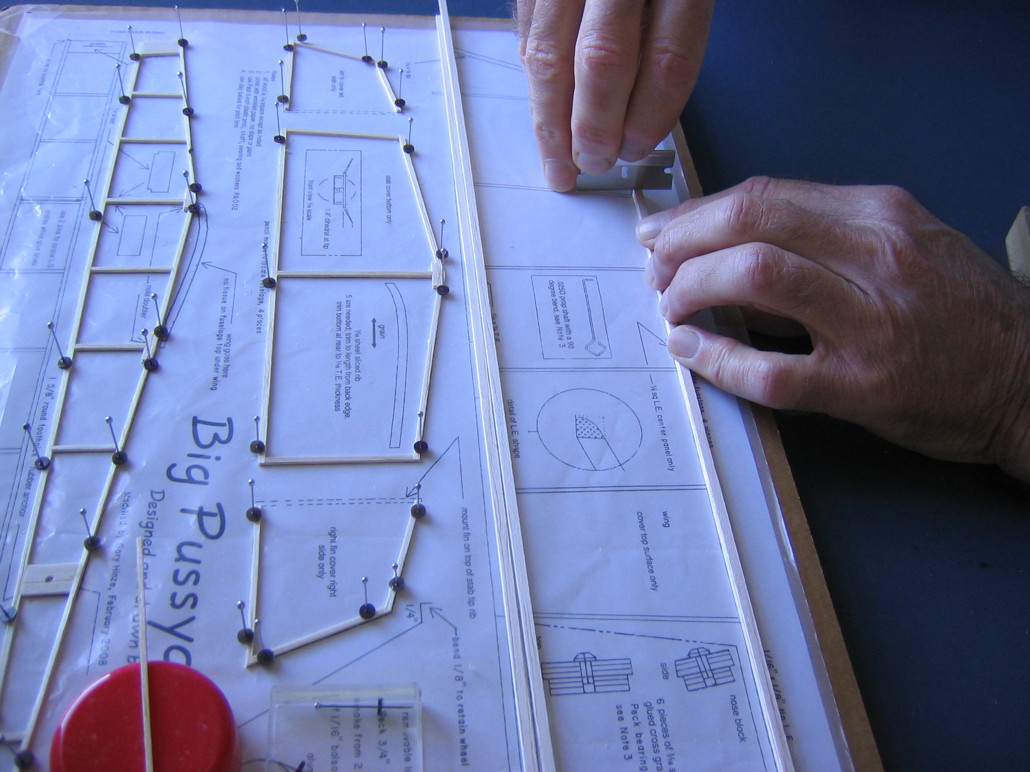
The glue on the first fuselage side is probably dry by now, so turn the board around, pull the pins, remove the first fuselage side and put it in a safe place. You can slide a thin object such as the back of the razor blade or a thin straightedge under the wood to separate it from the plastic sheet. This is a prying up rather than a cutting. Don’t cut through the plastic cover. Now build the second fuselage side. Put the pins in the same holes to be sure the second side is identical to the first.
Click HERE to go to Chapter 5.
One thought on “Big Pussycat Chapter 4 – Constructing the Fin, Tailplane, Wing and Fuselage Frameworks”