When we wind our rubber motors we count the turns. We do this to avoid over winding and breaking the motor, to limit the torque during initial test flights or to limit the height of the flight. Counting thousands or even hundreds of turns can be tedious and interruptions can cause us to lose count. Thus an automatic counter is desirable.
The New K&P Winder Counter
K&P make the popular winders we use for the small airplanes we discuss here. Now they have a counter. It can be bought as a separate unit to add to the winders you already have or it can be bought bundled with a winder. They work with the 5:1, 10:1 and 15:1 winders; they count turns of the crank. You must multiply the number displayed on the screen by the winder ratio.
I bought four of the bundled 10:1 winder and counter from Vintage Model Company. The cost is in pounds sterling. You can find the current exchange rate online to estimate the cost in other currencies. I expect that those suppliers who provide K&P winders in other countries will soon have the counters, too. Check with your favorite supplier.
Quick Instructions
1. Loosen the crank screw and remove the crank.
2. Place the ring of the counter base around the shaft housing and secure it with the self tapping screw. Don’t over tighten the screw.
3. Place the striker plate over the shaft with the beveled side toward the COUNT button.
4. Place the crank back on the shaft and secure it with the screw. Don’t over tighten the screw.
Note: The counter records the number of turns of the crank. Multiply by the winder ratio to get turns of the hook.
Continue for more detailed assembly and use instructions with comments.
Assembling the Counter to the Winder
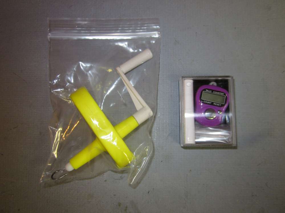
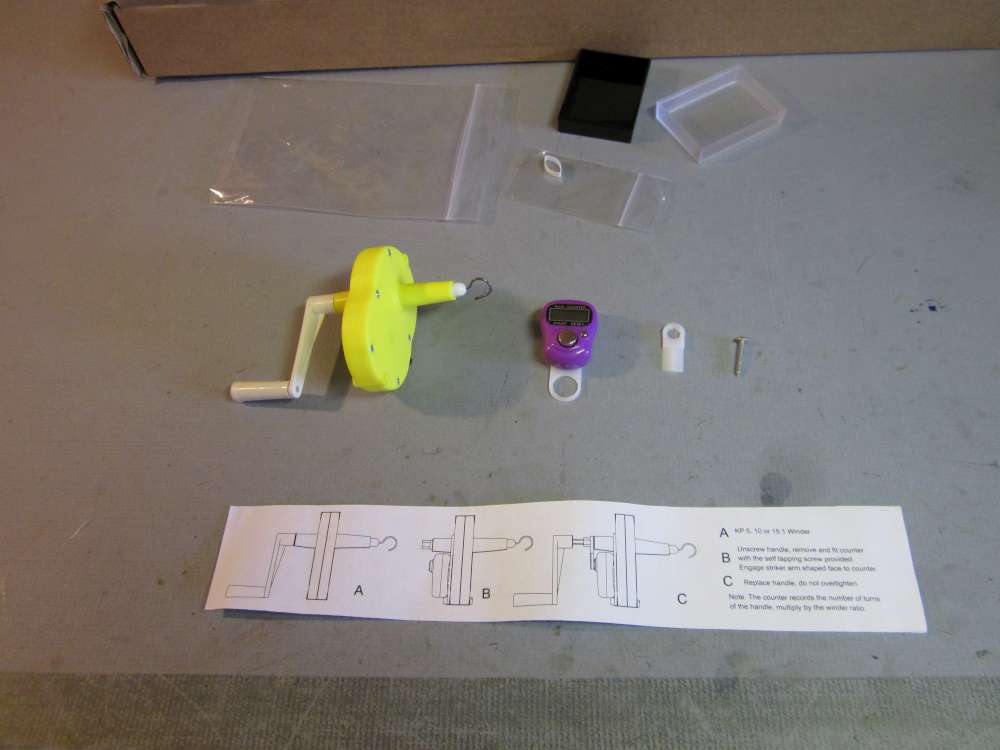
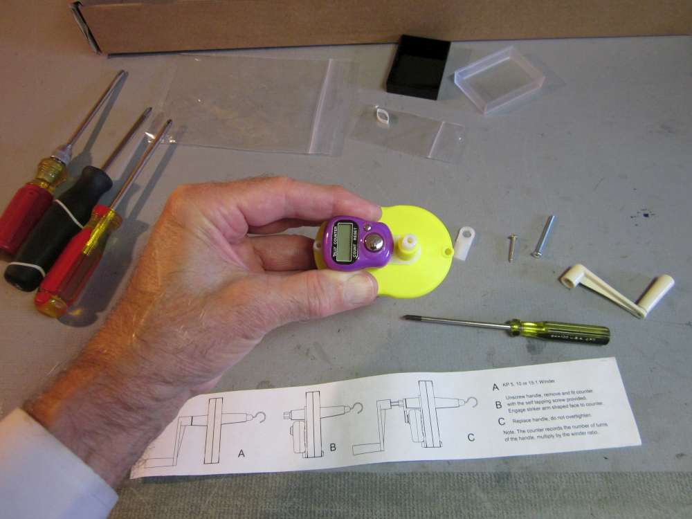
This is what you get, the 10:1 winder in a Ziploc bag and the counter in a small plastic box.
We start by taking everything out of the packaging.
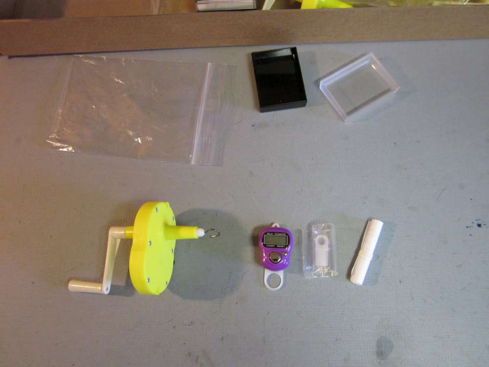
We find that there is a small Ziploc bag with a couple small parts in it and a tightly rolled, banded instruction sheet. Open these up.
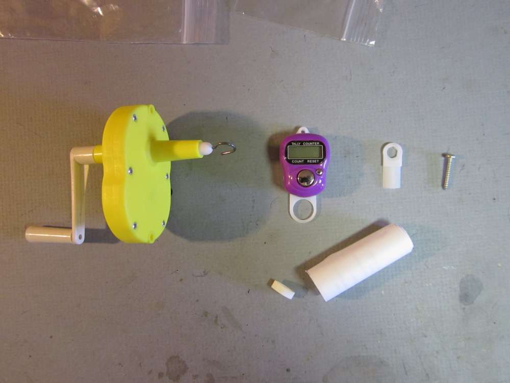
The small Ziploc bag contains a striker arm and self tapping screw. The instruction sheet is so tightly rolled that it will not lie open on the bench for us to read while assembling the unit.
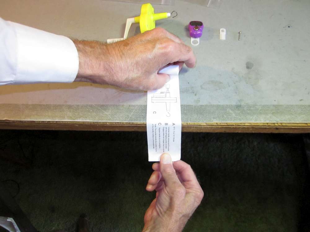
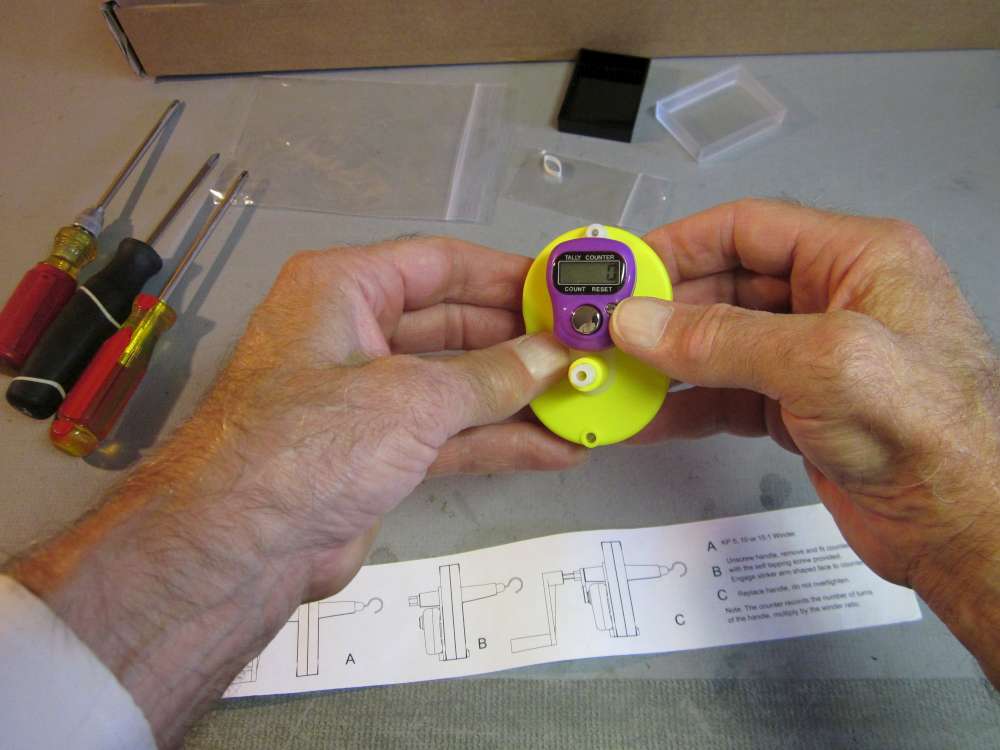
The instruction sheet can be flattened by drawing it across the edge of the table. The sharper the angle, the stronger the effect. It might take a couple tries to get it right.
Now we can read the instructions while using our hands to do the work. The instructions are a little bit unclear and incomplete, but the process is simple enough that many of us would not need them. If you are reading this, you won’t need them.
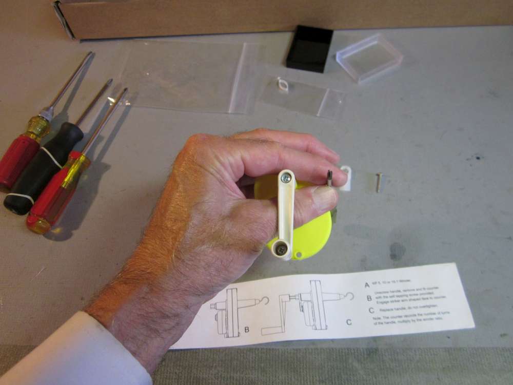
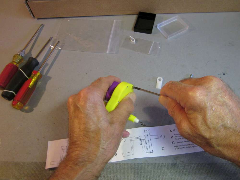
The first step is to remove the screw which holds the crank to the drive shaft. This is a small Phillips head screw. I used my small Phillips screwdriver.
It takes only a few turns to release the crank.

When the screw head is about here it is ready to come out.

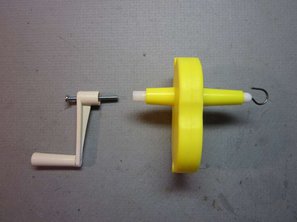
Pull the crank straight off the shaft.
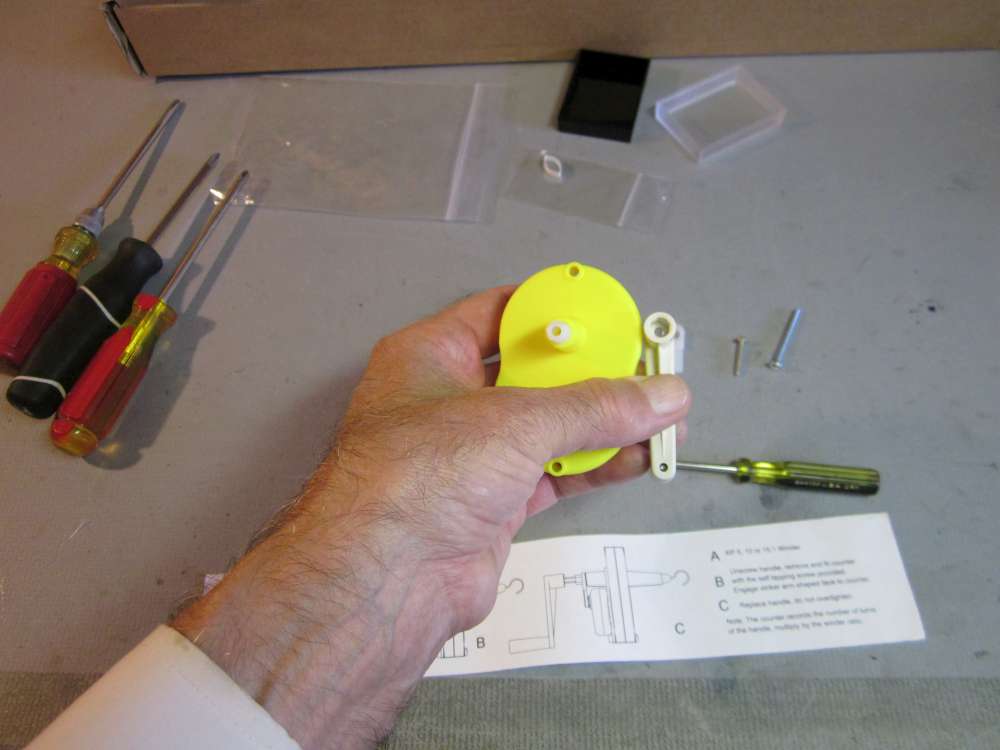
Notice that the shaft has a hexagonal cross section which matches the hexagonal opening in the crank.
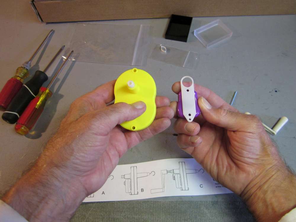
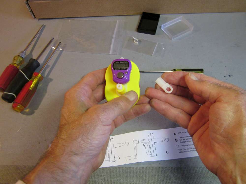
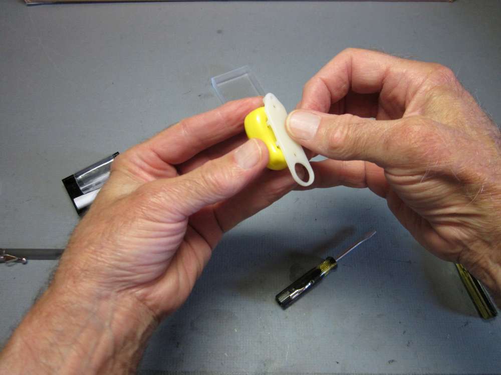
Notice that the counter is mounted on a white plastic base that has a large circular hole in one end that fits over the shaft housing on the winder and a smaller hole in the other end that will receive the self tapping screw.
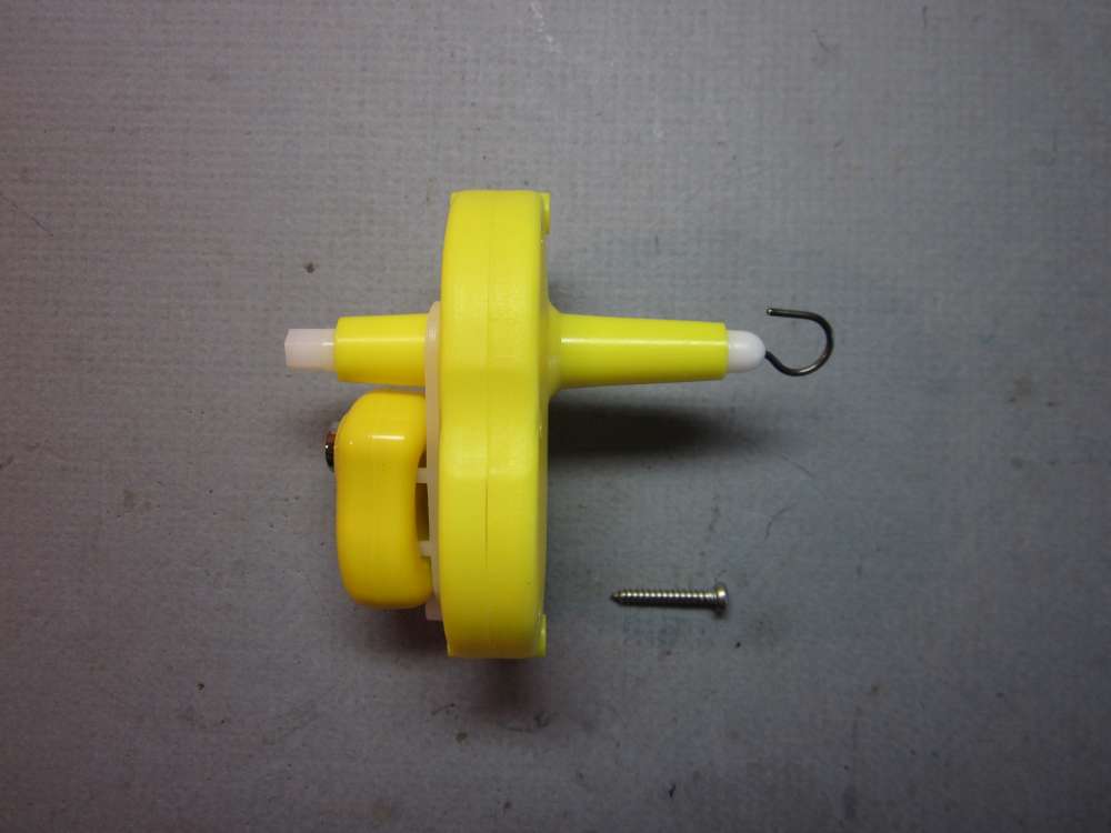
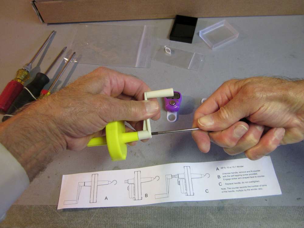
Put the circular opening in the counter base plate over the shaft housing on the winder.
Line up the smaller hole on the opposite end of the base plate with the opening that goes clear through the winder and insert the self tapping screw.
Tighten the screw down until it is snug, but don’t over tighten. When it stops going in, stop turning, otherwise the steel screw will drill out the plastic and it won’t hold the base plate to the winder.
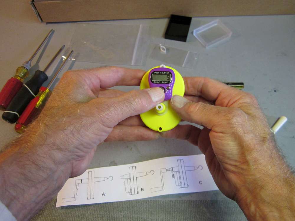
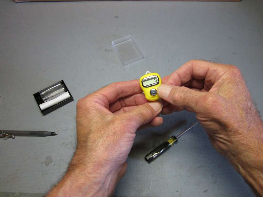
Try the counter. Every time you push the large button labeled COUNT the number displayed in the window increases by 1.
When you push the small button labeled RESET the number displayed in the window resets to 0. If there is no input for 15 minutes, the counter shuts off and the screen goes blank to conserve electricity.
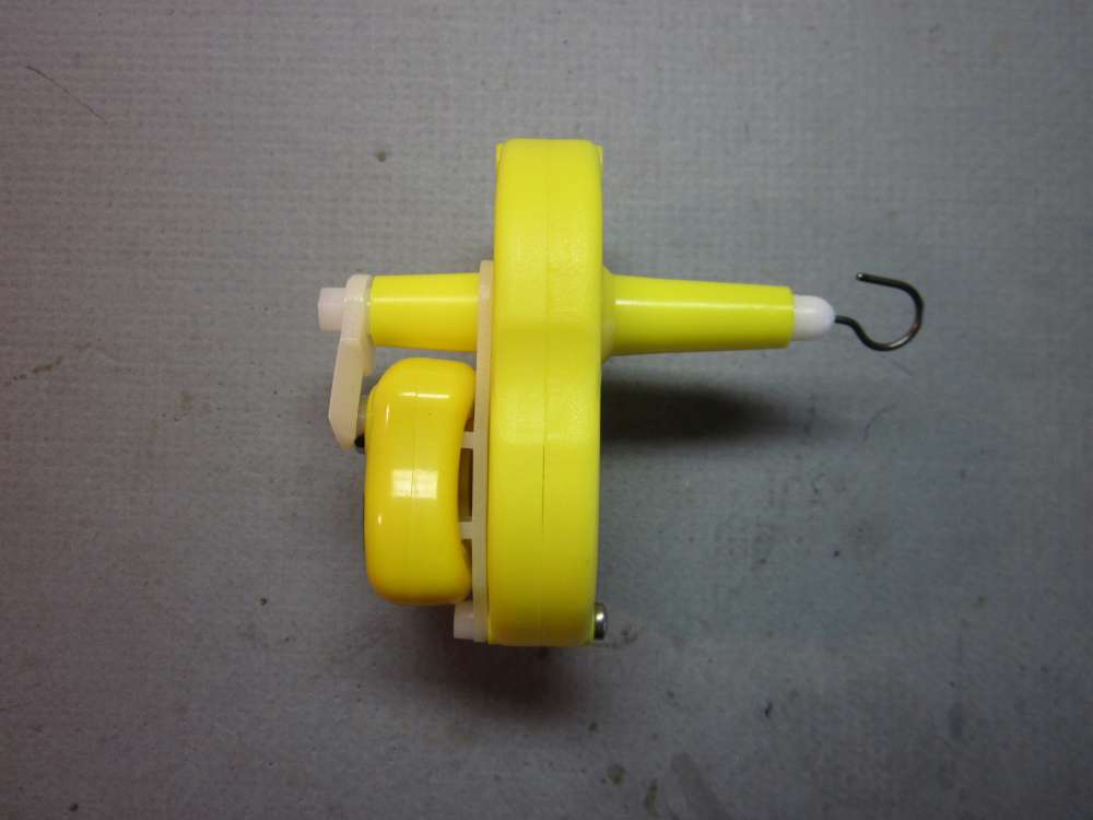
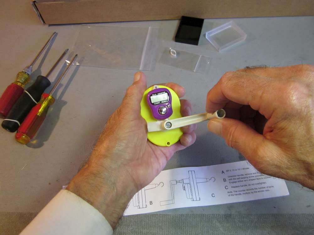
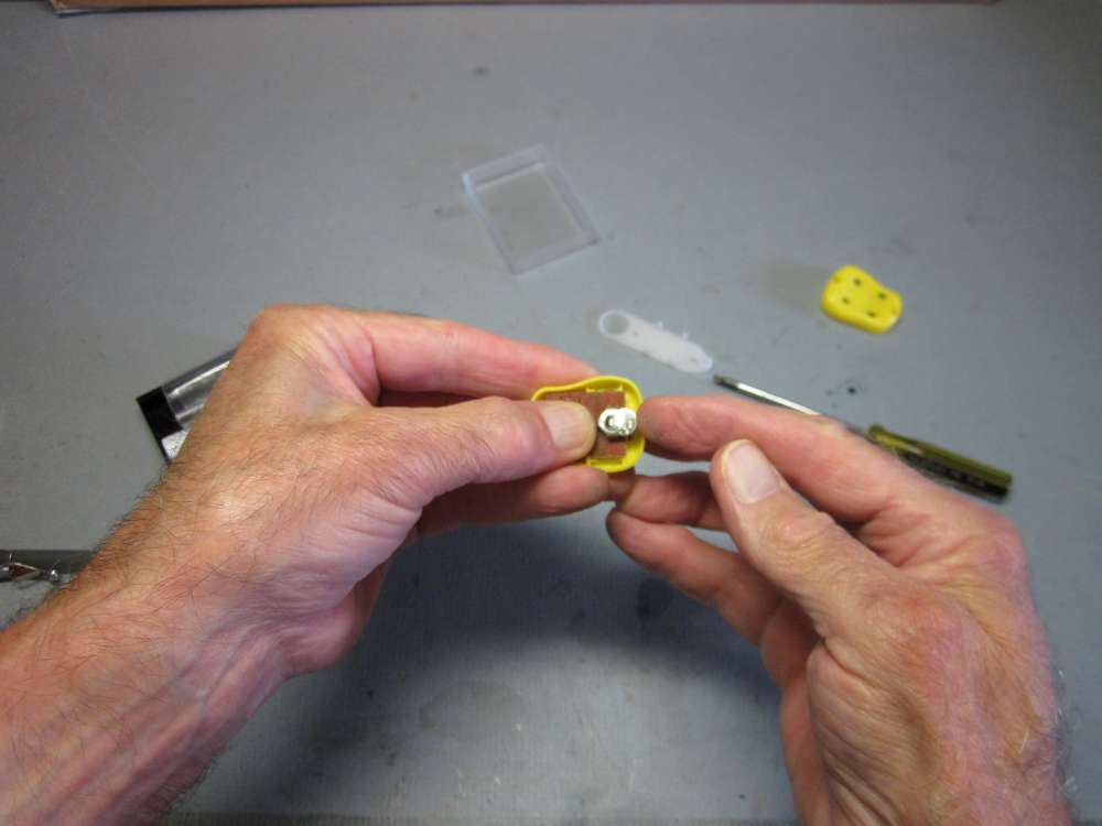
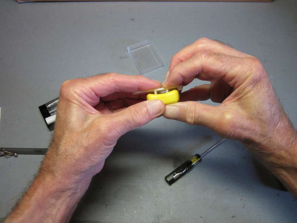
Now we are going to put the striker arm onto the shaft. Notice that one face of the striker arm is ramped. That side goes toward the counter button. Notice that the hole in the striker arm is hexagonal, to match the hexagon of the shaft.
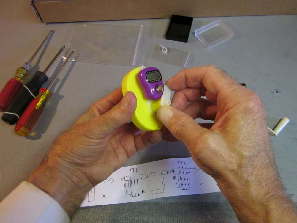
Put the opening in the striker arm over the shaft and press the arm down.
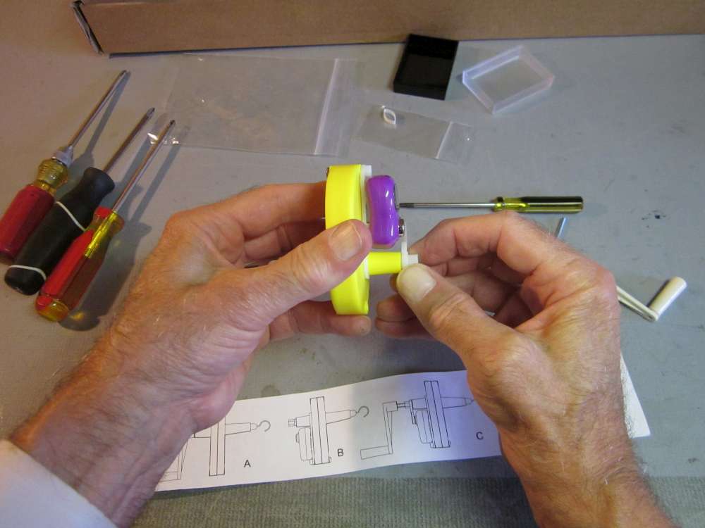
Press it all the way down.
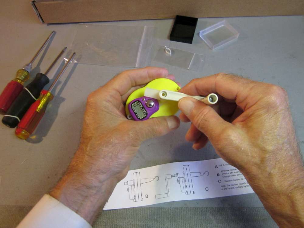
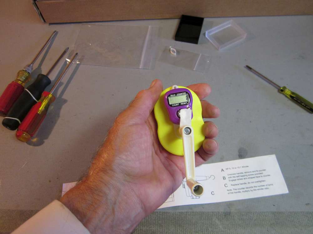
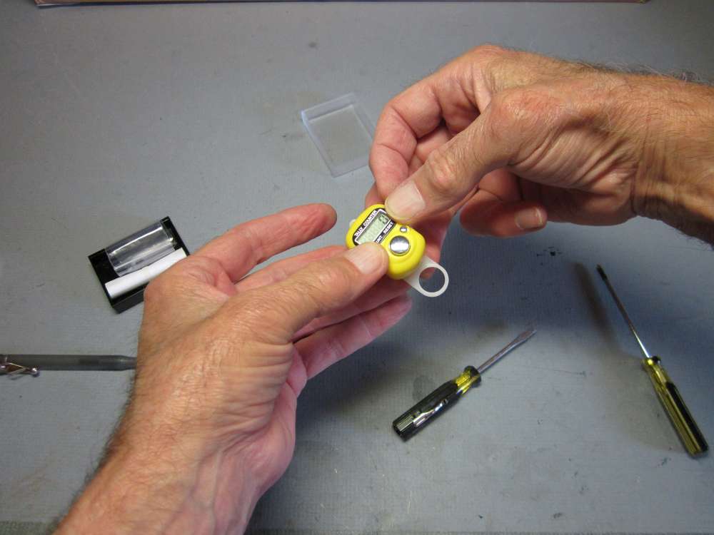
Put the crank onto the shaft. I lined the crank arm opposite the striker arm because I don’t want the crank arm to obstruct my view of the numbers on the screen. I also set it up so the opening on the hook is up when the striker arm is over the button. You might want to orient things differently, depending on your particular winding practice.
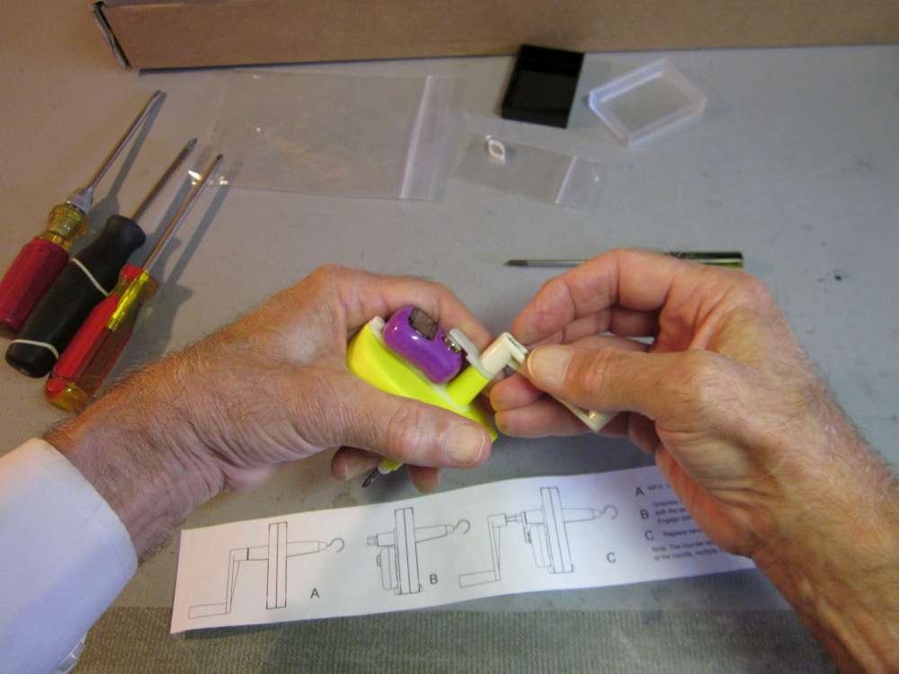
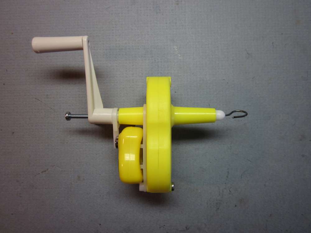
Press the crank firmly in place.
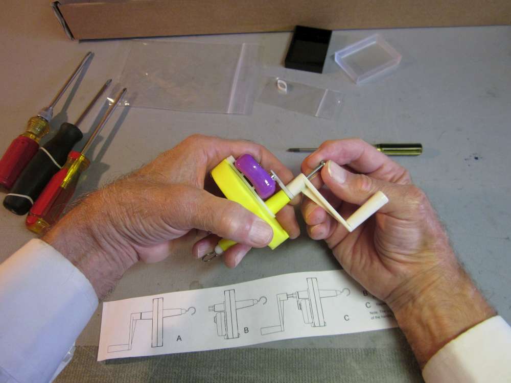
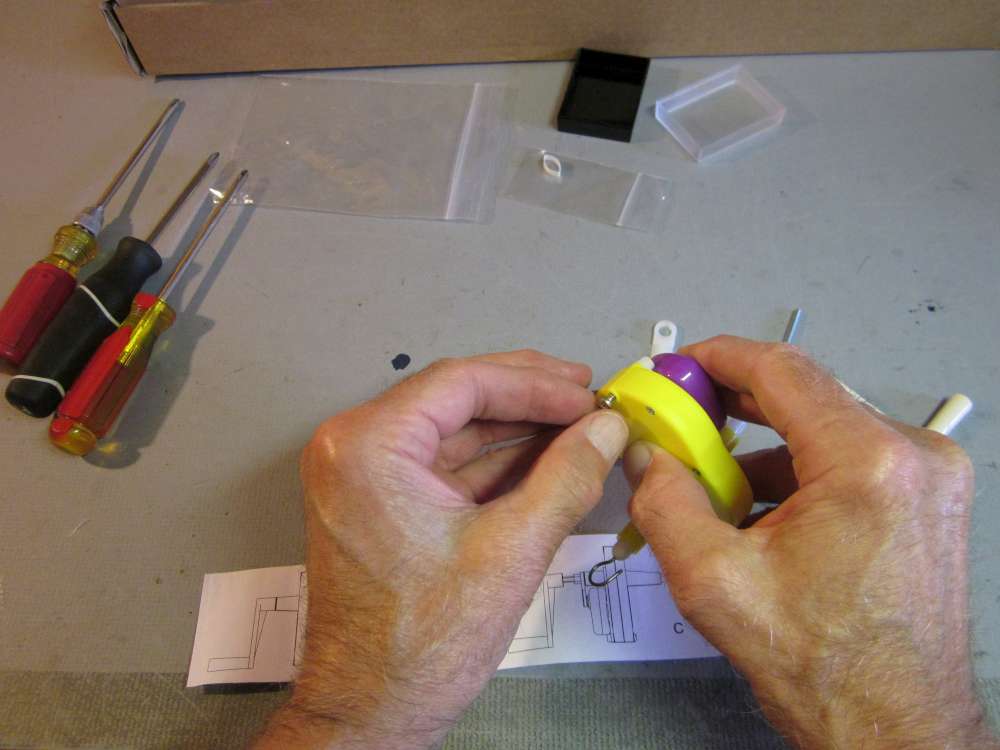
Insert the crank screw.

Tighten the screw down until it is snug, but don’t over tighten. When it stops going in, stop turning, otherwise the steel screw will drill out the plastic and it won’t hold the crank to the shaft.
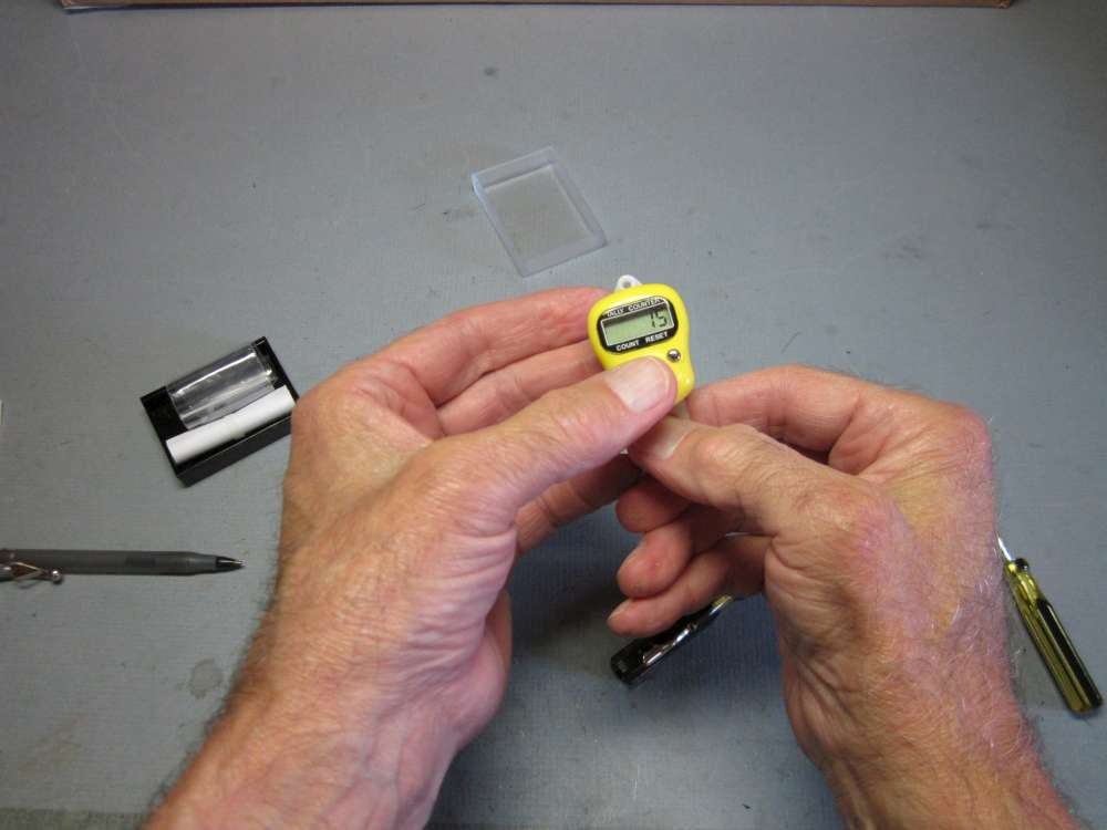
Test the winder to make sure everything is snug, turns smoothly and counts properly.
Using the Counter
Reset the counter to 0 and back the crank until the number 1 just appears in the window. This is where you start winding. Before winding a motor, reset the counter to 0 and back the crank into this position, then put the motor onto the hook.
On the 10:1 winder, the counter counts one unit for every ten turns on the rubber motor. To get the number of turns on the motor, multiply the count displayed in the screen by 10. For the 5:1 or 15:1 winders, multiply by the corresponding ratio. For more precise counts, you can estimate 1 turn for every tenth revolution of the crank. You can divide the cranking circle in half and eyeball fifths of the semicircle. I may put corresponding marks on the back of the winder. For most flying purposes, you may not require that degree of precision, but if you are torque testing rubber or doing flight energy testing, you may want it.
For indoor flying it is common to wind to a number of turns, then back off a number of turns. On this counter, you can wind to the initial turns, press the reset button and counter wind to the number of back off turns. It will not subtract turns going the other way, but it will count counter turns.
Be careful to not move the crank back and forth with the striker arm over the counter button. It will add a count for every pass. If you pause your winding, have the striker arm off to the side.
Safety Warning
When I have taught kids to wind motors, I tell them to hold the propeller and the winder waist high. This is so if the stretched motor snaps or something comes loose, nobody will get hit in the face by flying debris. With this counter, you must put your face in line with the counter screen which is in line with the wound motor. I recommend holding the winder at waist level, pause the winding and tilt the winder screen up to read it.
Replacing the Battery
The counter is powered by a tiny LR41 button battery. It doesn’t use much power and it automatically turns itself off when not used for 15 minutes, so the battery should last a long time. Eventually the battery will run down and require replacement. Here is how you do it.
It might be possible to remove the counter from the back plate without taking it off the winder. This instruction starts with the counter off the winder.
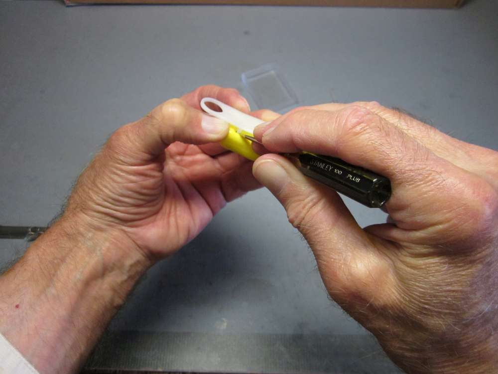
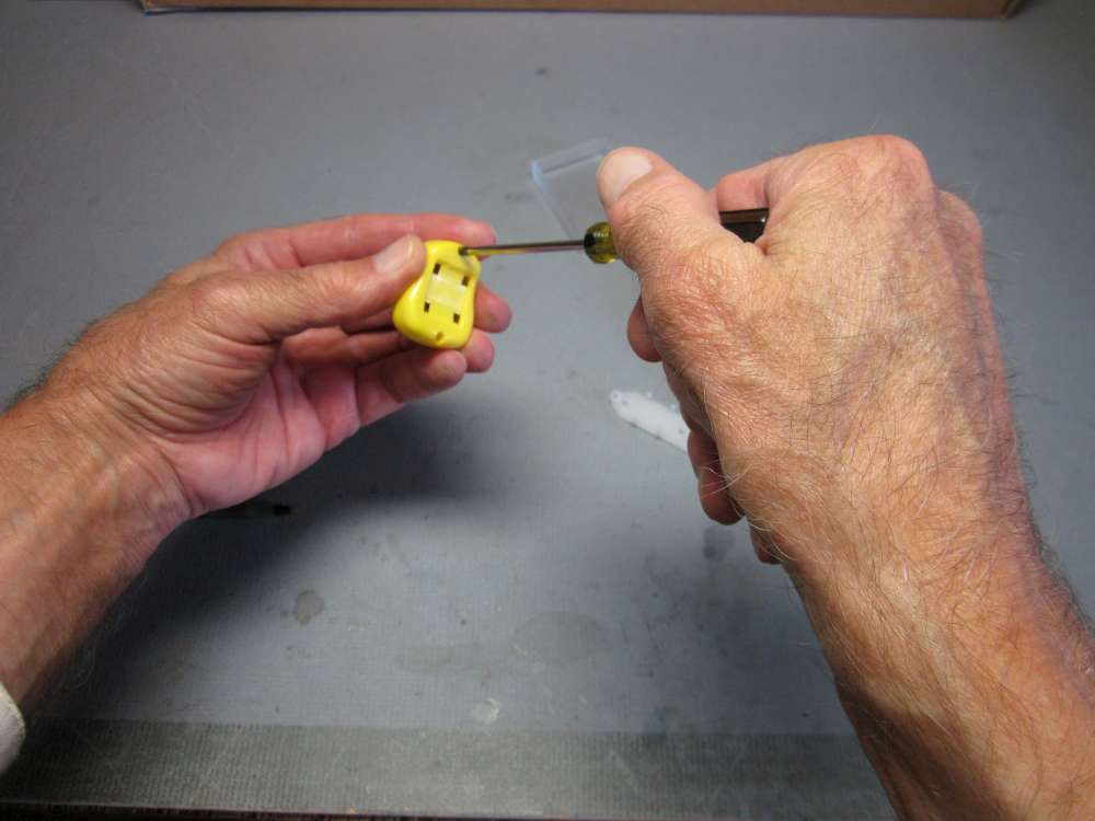
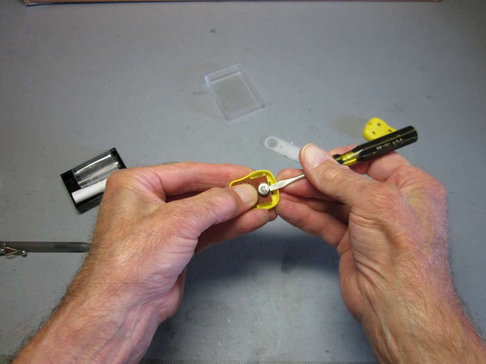
The back plate is held to the winder by four hooked pins that go into holes in the back of the counter. If you press the pins inward so the hooks clear the inside edge of the hole while pushing the back plate away from the counter, the pins will come out of the holes. Don’t press the pins any harder than necessary; you don’t want to break them. I wedged my thumb to press against the large end of the back plate to get the first pin loose.
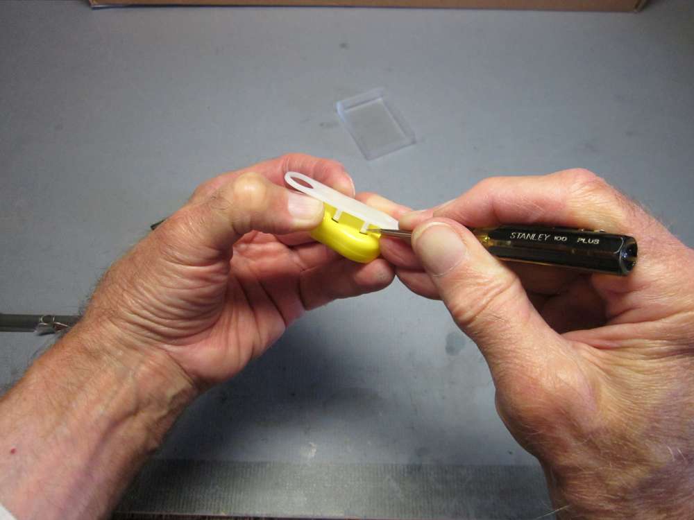
The same pressure worked to loosen the second pin when it was pushed inward with the screw driver. The other two pins can be disengaged by sliding the back plate inward and rotating it up.
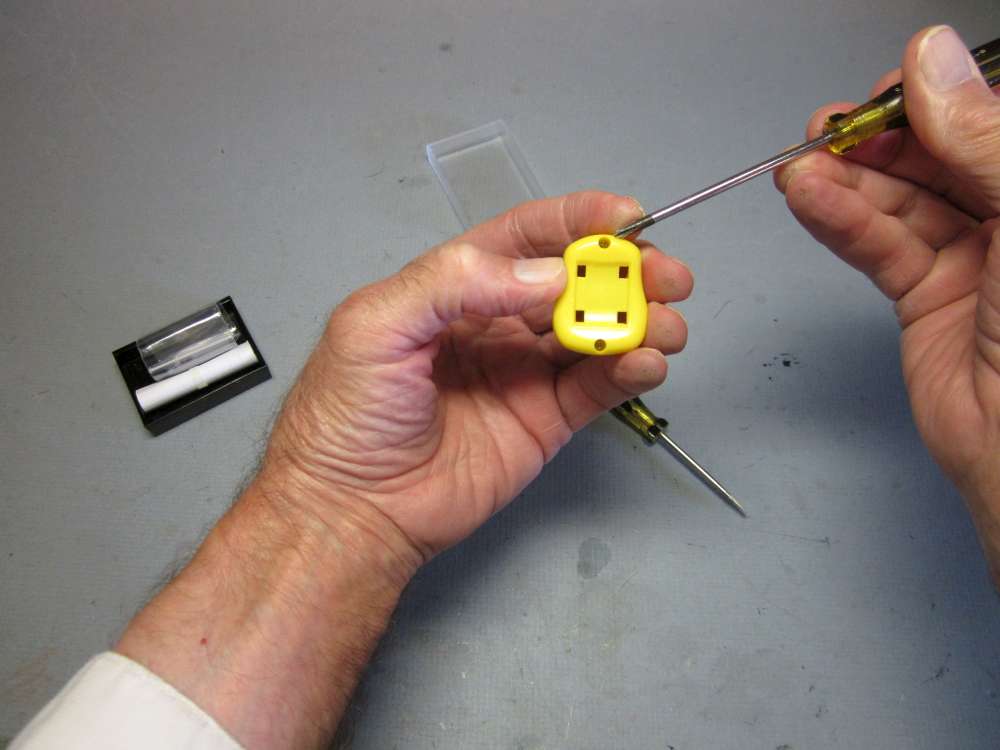
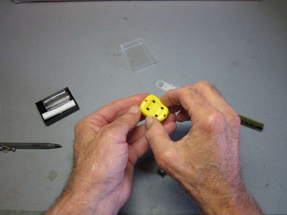
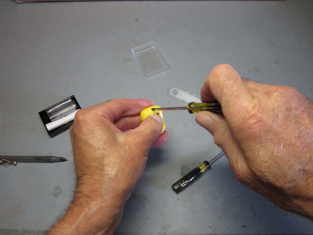
There are two round holes in the back of the counter. There is a tiny Phillips head screw at the bottom of each hole.
Unscrew both of these small screws.
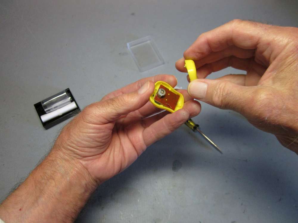
Remove the back of the case. Be careful to not spill the contents, everything is loose. Hold the circuit board in place with a finger while removing and replacing the battery. You don’t need to go any farther inside than this, the battery is now accessible.
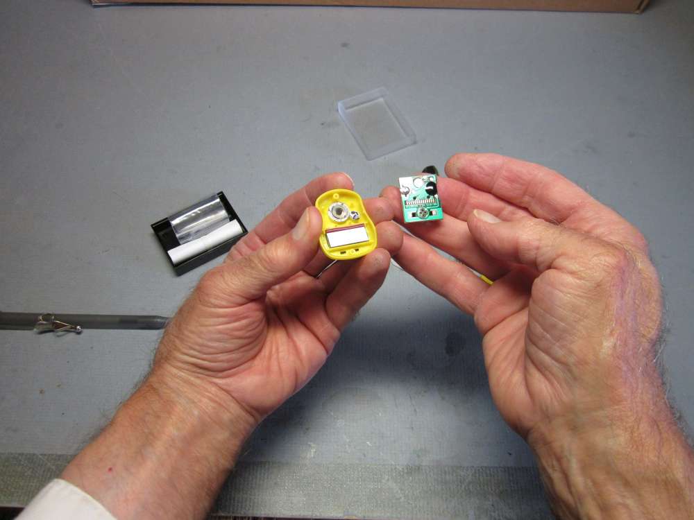
I made this picture to show how everything goes back together, in case you spilled everything.

Push the battery out of its holder. Note that it is an LR41 battery with the flat label side up.
Put the new battery into the holder with the button down, the label on the wide base visible.
Push it all the way in.
Put the back on.
Tighten the screws down until they are snug, but don’t over tighten. When it stops going in, stop turning the screw, otherwise the steel screw will drill out the plastic and it won’t hold the case together.
Align the pins with the holes.
Check that the loop on the back plate is on the same end of the counter as the COUNT button, as before.
Press the back plate in place. When the tapered hooks click, they are in place.
Check that the COUNT button works.
Check that the RESET button works.
That completes the battery replacement process.
Caution – Miscounts
I found that when winding very fast the counter will miss counts. This seems to be related to the reset speed of the electrical contact. I talked to the supplier. It can’t be fixed. This does not happen at moderate winding speeds. Try it yourself to get an idea of how fast is too fast. Count out 100 cranks and see what the winder says. It still winds plenty fast, just be a little patient. It is not a good idea to wind very fast, especially at the high end of the torque curve, because it heats the rubber and increases the resistance.
My thought and you thought is same in this plane. Justly I am starting a rubber band airplane channel on YouTube. My name is (Rashid) from Pakistan. Thanks for you (Pakistan rubber band airplane) video upload on youtube.
Is this your channel?
https://www.youtube.com/channel/UCK0guSXY21gAZ0xoq0K51Ew
Nice post Gary – I like that you have included the instructions to change the battery. Derek at KP Aero figures that the batteries will last ‘forever’ due to the low power draw and auto-off function, but it’s nice to know that the battery can be changed if needed. We have these for sale at Peck-Polymers and they are a very popular item! Here’s a link to our winders page: https://www.wind-it-up.com/collections/rubber-winders
Ingenious idea!