A torquemeter is an instrument used to measure the torsion in rubber motors for powering model aircraft. It consists of a piece of steel wire which is fixed at the back and and with a hook at the front end to which the rubber motor is attached. An indicator needle is fixed to the wire near the hook end and marks the torque against a dial. The operating principle is that there is a fixed ratio between the amount of torque applied and the angular deflection of the needle. Thus the angular deflection of the needle can be used as a measure of the applied torque.
Since 24 November 2025 I have been working on torquemeter wire, again. I bought two J&H torquemeters, intending to test one of the 0.015″ wires to destruction.
There are two tests. One measures the ratio between angle and torque. The second finds the torque beyond which the ratio is not consistent. The sample wire has two lengths associated with it, depending on which test is considered. In the first, the length is the distance between the end where the wire is attached to the disk and the point where it is fixed in the vise. In the second it is the distance from the point where it is fixed at the back of the torquemeter and the point where the indicator wire is attached to the test wire.
Torsion Coefficient
The first test measures the torsion coefficient; the ratio between the torque applied and the angular deflection of the wire. I have tried several methods for doing that, but the simplest and most reliable is with a torsion pendulum.
The spreadsheet shown there calculates all the parameters. I will not get into the derivation of the equations or the various unit conversions. I am using gram centimeters for torque because I will use these numbers to match motor torque to airplanes and motors weighed in grams.
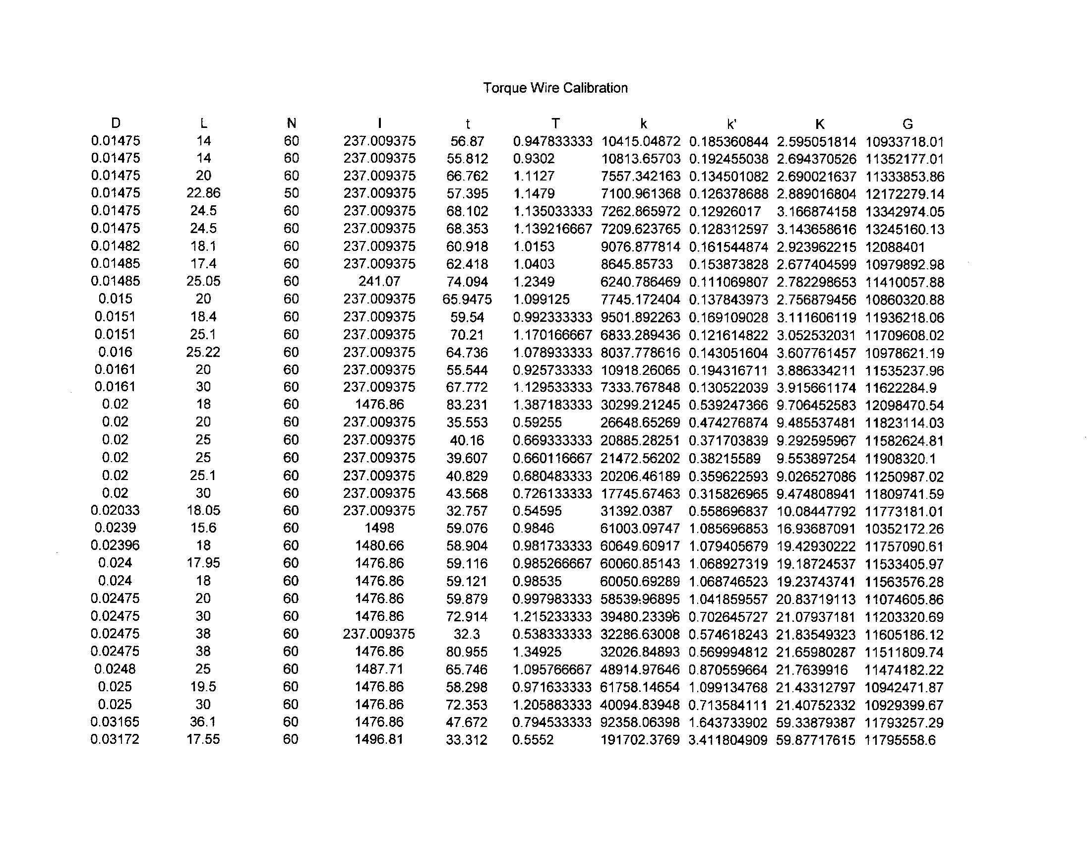
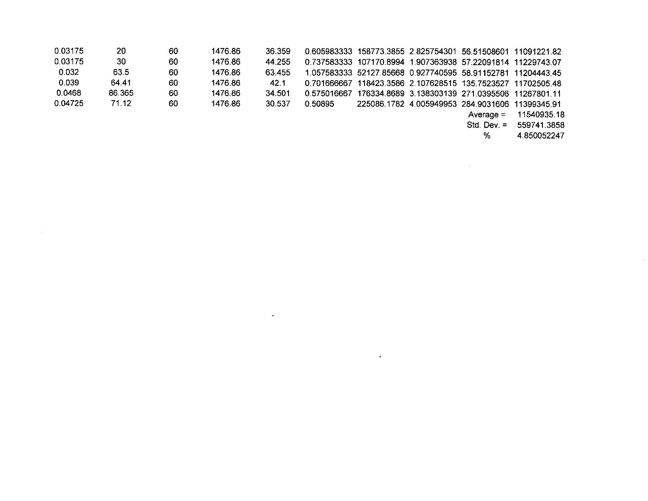
This is my latest table of wire tests. (12/15/2025)
The test method is as described below.
Draw a 15 cm circle on some heavy cardboard from a cereal or Graham Cracker box. (Larger diameter wire will require a larger diameter disk, as indicated in the I column in the table.) Cut it out precisely along the circle. Poke pinholes through the center and at a point 1/4″ off center. Weight it in grams to get its mass m. I find that the weight varies with atmospheric conditions, so it should be weighed before each test. Bend 1/16″ of one end of the wire to a right angle and another parallel right angle 1/4″ away to form a staple on that end of the sample that will fit into the holes in the disk. Bend 1/8″ of the other end of the wire at a right angle and parallel with the first end. Measure the distance between the bends in centimeters, this is the length L of the sample. Put this end through the center hole and pull it through until the staple engages the other hole and tape it securely in place. Clamp the 1/8″ end in a vise so the wire hangs vertically and the disk is free to rotate. Put a mark on the edge of the disk opposite you, so you can see the mark pass behind the wire as the disk oscillates. Rotate the disk to deflect the mark about 90 degrees and release the disk. As the mark passes behind the wire, start the stopwatch and count every time the mark goes behind the wire, going in the same direction, each full cycle. Count to some number N, typically 60 is good enough, and stop the watch. The watch gives the time t for N cycles. The swings will diminish, but the time interval will remain the same. Measure the diameter of the wire in inches at several places and find the average diameter D. I find that the wire is usually not exactly the nominal diameter. For example, for this test I measured the 0.015″ wire at seven stations, twice at each station, at right angles. The average of fourteen measures was 0.01485″ with a standard deviation of 0.51625%. That is the number to use in the calculations.
The moment of inertia of the pendulum disk is given by I = m r^2, calculated on a pocket calculator.
I = moment of rotational inertia of the disk in gram centimeters squared
m = mass of disk in grams
r = radius of disk in centimeters
^ – exponentiation
The following are entered into the table:
D – the diameter of the wire in inches
L – the length of the wire in centimeters
N – the counted number of cycles of the pendulum
I – the moment of inertia of the disk in gram centimeters squared
t – the stopwatch time for N cycles of the pendulum
The spreadsheet calculates the following:
T = t/N time interval of one cycle, seconds
k = 4 π^2 I / T^2 gm-cm of torque per radian of deflection for wire of length L
k’ = k 360/2π gm-cm of torque per degree of deflection for wire of length L
K = k’ L gm-cm of torque per degree of deflection per unit of length, establishes a relationship between L and k’ for other lengths of wire
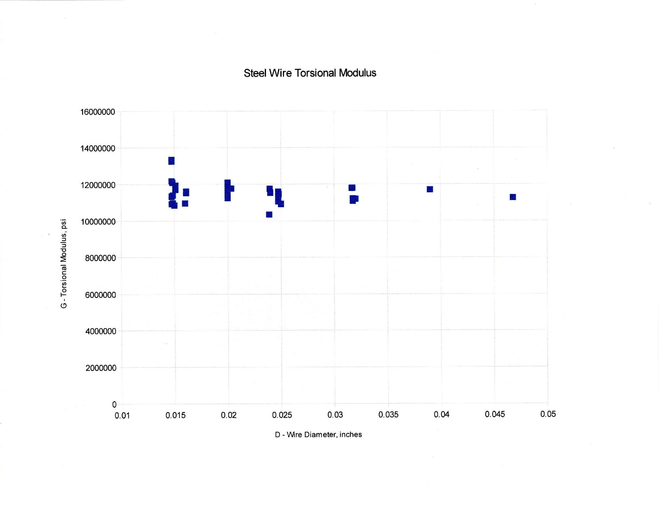
G = 0.199429737 l k’ / D^4 torsion modulus in pounds per square foot
G is the coefficient use in the equation some sources use to calculate the ratio between angular deflection and torque. Note that its value is fairly consistent, standard deviation is only 4.85% of the average. Some sources say that G varies with diameter, but that does not seem to be the case. See the graph. If you want to use the G equation, the value of 11,540,000 is good. I would use this only for preliminary design estimates. If you want an accurate torquemeter, I recommend calibrating your own wire.
k’ is the number we use to convert a dial reading in degrees to a torque in gram centimeters for a particular length of wire. Suitable conversion factors may be applied for other units of deflection or torque. For example, to convert gram centimeters to inch ounces we divide by 2.54 and 28.3495 to get k” = k’/72. For a 12 hour clock dial and in-oz, we multiply by 360/12 to get k”’ = 30 k” = k’/2.4. For a dial with 10 divisions and in-oz, we multiply by 360/10 to get k”” = 36 k” = k’/2.
K is is used to calculate k’ for lengths other than the test length. K = k’ L, thus k’ = K/L for another value of L.
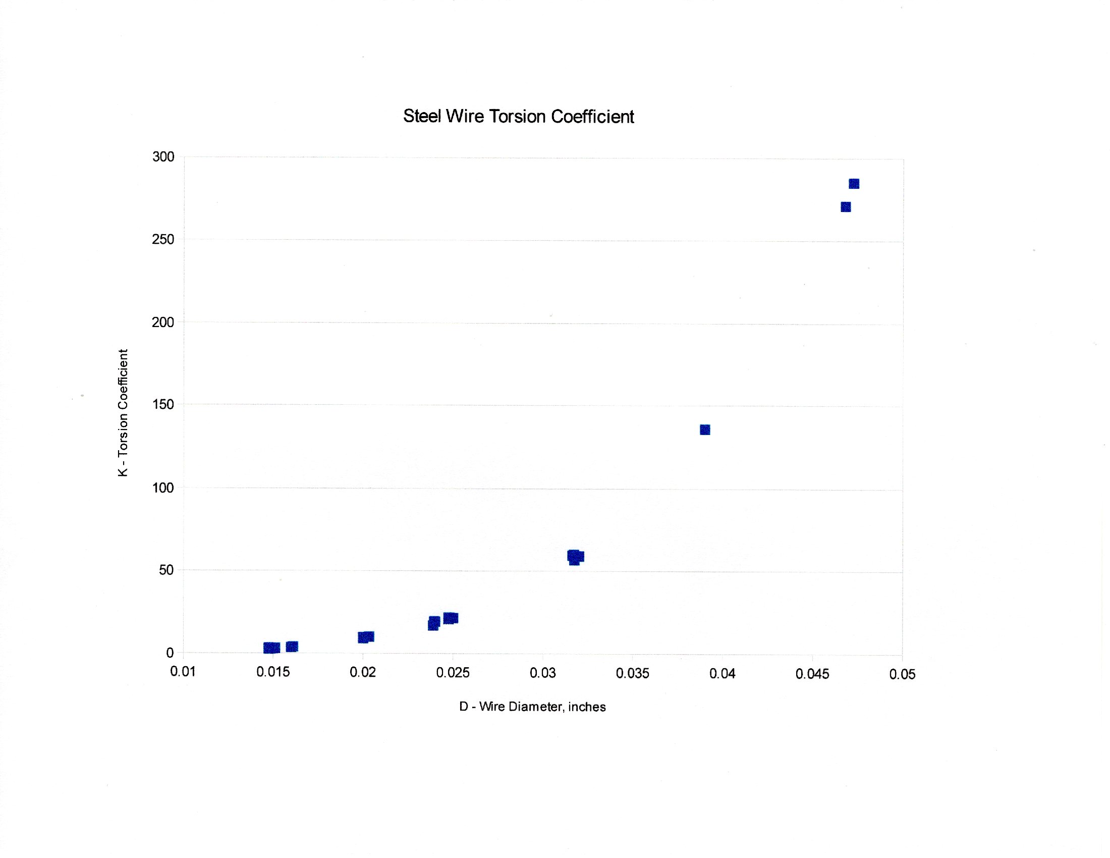
There is a strong relationship between K and D. In fact, K = 57,870,000 / D^4 is a more direct way to estimate the ratio of torque to deflection for wire of diameter D than the G equation.
Yield Torque
The second test is to measure the yield torque. There is a range of torques within which the angular deflection is linear and consistent. The deformation is elastic; the wire returns to its original state when the stress is removed. The needle goes back to zero. However, when you exceed yield stress, the needle does not go back to zero. The steel is permanently deformed. It will no longer work to reliably measure torque.
I saw this years ago when I bought two of the Dirt Cheap Torque Meters.
I found that when deflected to 10 O’clock, it returned to zero. When deflected to 11 O’clock, it didn’t quite make it all the way back to zero. When deflected to 12 O’clock, it went back to 0.2 hour, not zero. The steel is permanently deformed, no longer in the linear range, not reliable for measuring torque. This tells me the yield torque is just below 11 O’clock, but does not get an exact value.
The amount of permanent deformation, the amount by which it does not return to zero, is called the set.
An exact value for yield torque may be found by extending the test to get several values of set with the corresponding deflection, then plot the graph of deflection vs. set and fit an equation. I tested a 17.4 cm piece of the 0.015″ wire. I deflected the needle to D in steps of 0.1 unit, where 10 units = 360 degrees, and let it return to the unstressed state. When the needle did not return to zero, I recorded the reading as S, set.

The table, upper left, shows the readings of deflection D and set S. The block of numbers below the table is the statistical least squares fit (LINEST) of a linear equation to the data, as shown below that block. The equation shows D as a function of S; D = 3.722 x S + 0.7383. The regression finds a slope of 3.722 and an intercept of 0.7383. The intercept of that equation is the value of D when S is zero. That is the maximum value of D which does not cause yield. That deflection corresponds to 265.79 degrees. The torsion pendulum test of this wire found 0.1623 gm-cm of torque per degree of deflection. Thus 265.79 x 0.1623 = 43.14 gm-cm = 0.5991 in-oz is the do not exceed torque for this wire. This depends only on the diameter and is the same for any length.
On the J&H torquemeter, with active wire length 16.5 cm = 6.5″, yield torque of 43.13 gm-cm = 0.5991 in-oz occurs at 0.7001 or 252.04 degrees, less than full scale. If you want to measure higher torques, you must use thicker wire. If you want this wire to indicate yield torque at full deflection of 360 degrees, the wire must be (360/265.79) x 16.5 = 22.34 cm = 8.78″ long.
After twisting this wire past yield, I redid the torsion pendulum test. The cycle time was 62.454seconds, compared with the original time of 62.418 seconds, substantially the same. We may conclude that the rate of angle versus torque is also the same. I found that the set could be reversed to zero by twisting the wire backwards by about the same amount as produced the set. It seems that the wire may be restored to original condition as long as it hasn’t been stressed too far. Small amounts of set are reversable.
Torquemeter Design
You can make your own torquemeter. There are numerous plans on the Internet. There are the two kits referenced above. Coach Brian demonstrates making one from paint stirrers and 0.020″ guitar string.
These numbers allow us to design a torquemeter to match the torques we must measure.
The first step in torquemeter design is determining the maximum torque we will need to measure. That is done by measuring the breaking torque of the motors we intend to use. And here we have a chicken and egg problem; how do you measure the torque when you don’t have the right torquemeter? You start with a thin motor that is clearly small enough to test. You wind it up until it breaks, calculate the torque coefficient Kq and use that coefficient to calculate the torque of the larger motors you plan to use.
Or you can pick a number you find in the literature. The average of nine tests was Kq = 109,348.22 with a standard deviation of 25.96% of the average. Considerable variation. The Tan II rubber I have been using has a value of 101,750. These test numbers are probably good to three significant figures, so for this example we may use 109,000. The motors being used are two strands of 1/8″ rubber. Cross sectional area is S = number of strands x thickness of strand x width of strand = 2 x 0.042″ x 0.125″ = 0.0105 square inches. Breaking torque is Kq x S^1.5 =109,000 x 0.0105^1.5 = 117.28 gram centimeters = 1.63 in-oz.
Here we run into a little bit of a problem. We need to know the yield stress of our wire. You would hope there would be a standard value, but there isn’t. Steel properties vary just as the properties of rubber vary from batch to batch. (I’m beginning to think they vary with temperature, too, as with rubber.) There is a parameter called yield stress τmax (tau maximum), but the values in the literature are all over the place, ranging from 21,000 psi to 177,000 psi. I won’t bore you with details, but the various collections have standard deviations around 50% of the average, not good enough even for preliminary design estimates.
Just as a curiosity, the equation for yield stress is τmax = Qmax/226.2 D^3 where
τmax = yield stress in pounds per square inch
Qmax = maximum torque before yield, as determined in the S regression, in gram centimeters
D = wire diameter in inches
You must measure your wire torque against set to find Qmax, maximum torque which exceeds yield stress, for each wire diameter. You pick a wire diameter whose yield torque is greater than that of your rubber. My recent tests found the following:
D Qmax
0.015″ 64.86 gm-cm
0.016″ 30.26 gm-cm
0.020″ 44.28 gm-cm
0.0248″ 303.92 gm-cm
0.03165″ 286.89 gm-cm
You note the irregular progression. The 0.03165″ (nominal 1/32″) wire is the smallest that exceeds our required 177.28 gm-cm maximum torque. (Maybe we should go looking for some other 0.024″ or 0.025″ wire, but I’m working with what I have.) We want that 117.28 gm-cm to occur at one full revolution on the dial, 360 degrees. That is a k’ = 177.28 / 360 = 0.4924 gm-cm/degree. We can use this to determine the required length of the wire. The K value for this wire was 59.34 and since K = k’L, we can solve for L = 59.34/0.4924 = 120.51 cm = 47.44″. This is tough, since the wire generally comes in 3′ lengths! We could cut this is half and restrict the angular deflection to half the dial, never go more than 180 degrees. Or we could go looking for some tougher wire.
Let’s consider the 0.0248″ wire. We still have k’ = 0.4924, but K = 21.76, so L = 21.76/0.4924 = 44.19 cm = 17.39″. Again, we could halve the length and use just half the dial. That would be a practical size.
The above is a work in progress and should not be taken as the final word.
Practical Applications
Students in the Science Olympiad helicopter competition have been told to wind to full scale to put in one inch ounce of torque. That will fail either of the referenced torquemeters at less than one inch ounce. Also, I believe we need more than one inch-ounce of torque for helicopters. We need thicker and longer wire to measure the torques we will need for these helicopters.
So, helicopter engineers and test pilots, what can we do?
Last year my helicopter required 24.43 gram centimeters = 0.34 in-oz to hover. It was overweight. This is within the range of the 0.015″ wire torquemeters. So you can at least measure the hover torque, which is necessary to design the rubber motor. This torque is expected to equal the average of the torque of the motor. Breaking torque is typically five times the average torque, so we are looking to measure torques in the neighborhood of 117.15+ = 1.63 in-oz. (Close to the 1/8″ rubber breaking torque!) I will find and test more samples of wire and design a practical torquemeter to measure in that range. We must be able to measure up to the breaking torque of our motors. When we have hover torque and other properties of the helicopters and a torque curve for our rubber, we can size the motors for best flight times.
Gary Hinze