I bought two of the Dirt Cheap Torque Meters (DCTM) from Laser-Cut Planes.
https://lasercutplanes.com/index.php?p=1_5
They have a 12 hour clock dial with unknown units. I wanted to calibrate the 0.015″ steel wire so I could get actual torque values from it, so I can show how to take measurements and plot a torque curve for specific energy measurements of rubber and flight trajectory calculations. I tried to use various forms of the usual lever arm with a weight method and (again) found it to be tedious and unreliable. Then I had the idea to make a torsional pendulum to measure the torsional modulus of the wire. That is the value G in this post on making and using torque meters.
https://modelflight.com/how-to/the-value-and-use-of-torquemeters/
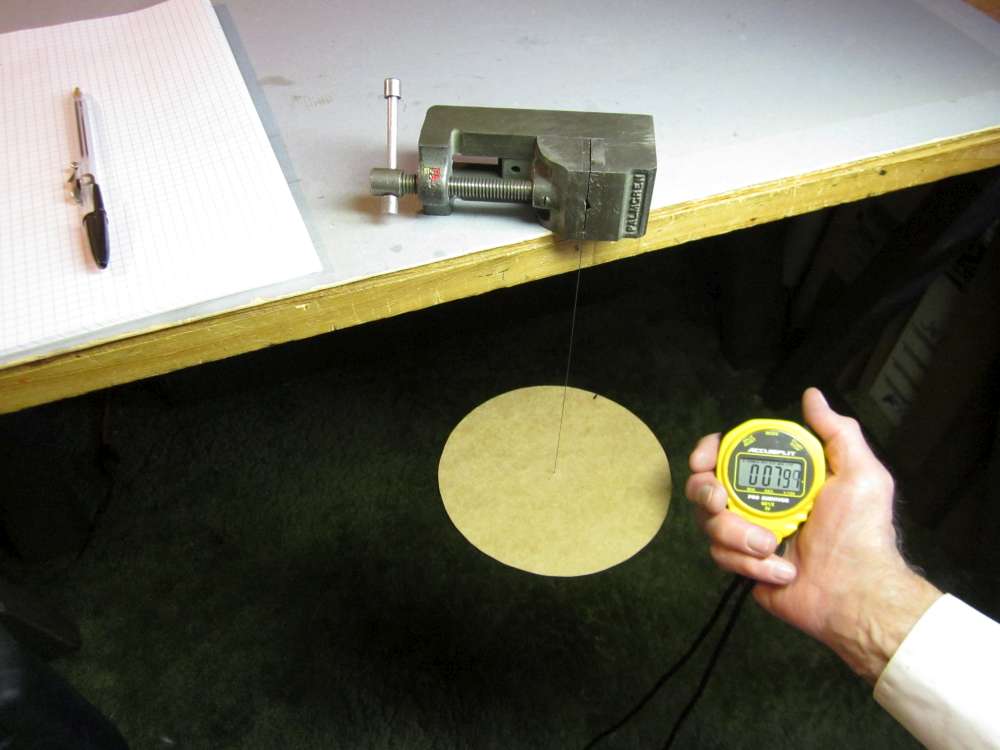
The method involves rigidly mounting a disk at one end of a piece of wire and clamping the other end of the wire in a vise, so the wire hangs vertically. The disk is a piece of flat cardboard from a heavy duty cereal box.
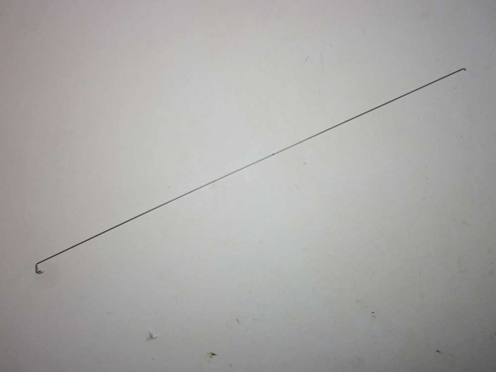
The wire has a flat U, staple, shape on the bottom end, which is threaded through two holes in the disk and taped in place. The top end has a short right angle bent over for the vise to grip and which defines the length of the test wire.
Displacing the disk at an angle around the wire axis and releasing it causes it to oscillate in rotation. (Sometimes it has to be confined at first to prevent swinging back and forth.) Measuring the period of the oscillation allows calculation of G, per the formula in the link and the torsion pendulum formula. (Note that the T in that link is torque, not cycle period, as here.) Position your eye so the mark on the edge of the disk aligns with the wire when the disk is not displaced. Count zero and start the watch at the first pass and add one to the count at every other pass. We are counting the full cycle, over and back.
The moment of rotational inertia for the disk is I = mr^2/2, with the mass of the uniform disk m in grams and the disk radius r in centimeters. (r^2 is r squared.) The period of the torsion pendulum is T = 2 pi SQRT(I/k) seconds per cycle. k is the torque coefficient for the wire, the ratio of torque to angular displacement, in dyne centimeters per radian.
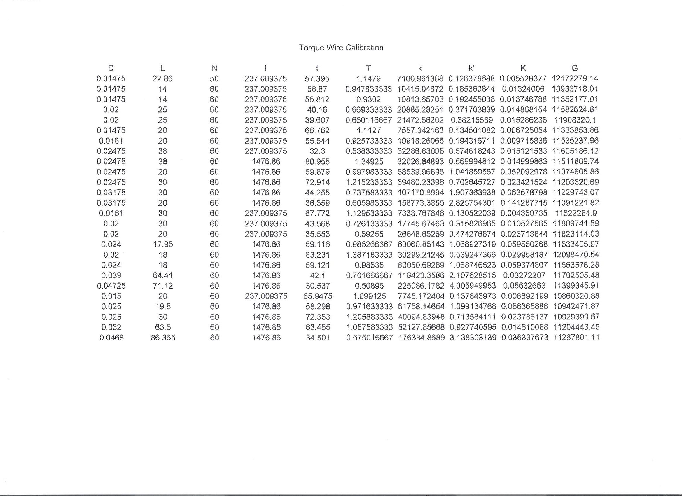
While I was at it, I tested all the wires in my shop. Here is a table of the results. D is wire diameter in inches, L is sample test length in centimeters, N is count of cycles, I is moment of inertia of disk in gram centimeter centimeters, t is time for N cycles, T is cycle period, k and k’ are torsion coefficients in gram centimeters per radian and degree specific for length L, K is torsion coefficient in gram centimeters per centimeter degree and G is torsional modulus in psi. Yeah, weird combination of units. Isn’t it great that we have so many standard units to choose from? Glad I have a spreadsheet that can store all those conversion factors.
There is an implication in the link that there is a systematic relationship between wire diameter and G. Here is the graph of G versus wire diameter D.
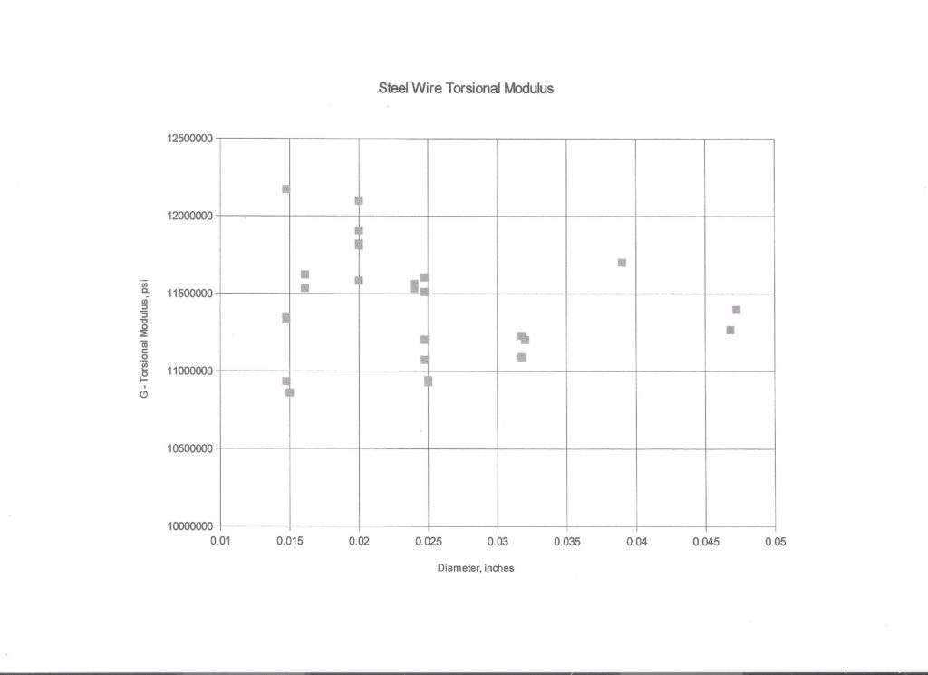
It looks like there is quite a bit of scatter, with no obvious trend, but consider that the range here is way above zero, 10,033,718 to 12,172,279, so we are looking at it through a microscope. Average 11,434,801, standard deviation 639,562, amounting to 5.59%. If you use the average, you probably won’t be off by more than 3%. The individual test measurements had standard deviations of a fraction of a %. Since the test method is pretty simple, I recommend you test your wire to get best accuracy in your torque measurements. The average G can be used for a preliminary estimate of the required length and diameter.
I found that with 11.2 cm between the fixed end and the indicator needle, the DCTM would indicate 1.0 inch ounce at 10:00 O’clock. However, after twisting it to 12:00 O’clock, it would not go back to zero; that much torque exceeds the elastic limit of the steel wire. To go higher than 1.0 inch ounce requires a larger diameter wire of much greater length.
I’ve gone backwards with this principle, measuring the moment of inertia in yaw of an entire model by suspending it on a wire and giving it a little angular displacement. My method was approximate, because I calculated the torsional stiffness of the wire by measuring it’s size. If I’d had measuring gadgets with more precision, I could have been more precise. I wonder how uniform your disk’s material is?
Here’s what’s probably a better idea for measuring the radius of gyration. Given that and an accurate weight measurement, it should be easy to calculate the moment of inertia.
http://www.rcgroups.com/forums/showatt.php?attachmentid=1829378
A trifilament pendulum is a better way to measure the moment of inertia of a model. Keep air effects in mind.
The cardboard material is sufficiently uniform for my purposes. It should be weighed right before the measurement, handle it lightly. It absorbs and evaporates moisture.