Alphonse Penaud’s 1871 Planophore was the first successful, stable model airplane powered by twisted rubber bands. That makes it very interesting to model airplane enthusiasts.
I have just posted my translation of Penaud’s original article “Self Propelled Aeroplane with Automatic Equilibrium” from L’Aeronaute, January 1872.
As I was translating the original article from the French, I also looked up the derivation of the name Planophore. From the Greek:
Penaud’s article is interesting for what it says and for what it does not say. Many familiar fundamental principles of aeronautics were not known in his time. Given that so many important principles were not known until years or decades later, it is even more impressive that he was able to work with vague and incomplete understandings to successfully fly his Planophores.
For a modeler wishing to produce a reproduction Planophore, the main parameters are there, but important details are left out. Penaud didn’t leave any detailed plans, drawings, material schedules or other construction details. He burned everything right before he committed suicide. There is much speculation and contradictory information. It will be up to you to fill in the details and work out the trim if you want to build a flying model. I have gleaned a few hints.
Bill Hannan published an extensive report on the Planophore, “Penaud & His Planophores” in Stick & Tissue International, pages 6-9. It is interesting for the wide variety of depictions of the Planophore and the number of replicas built by modelers. He continued the Penaud story in Volume Number Two of Stick & Tissue International, pages 2-5, which quotes Penaud’s instructions to Thomas Bennett on flying a Planophore that Bennett had purchased from Penaud in late 1874. This volume includes plans for Planophore models by Hannan, Parham and Magrath. Bennett reported Penaud’s paper to the Aeronautical Society of Great Britain and added a few details.
Hannan first published his report “Pénaud Planophores” in the August 1990 issue of Model Aviation. If you are a member of AMA, you can view the MA archive at the AMA web site. Access requires a username and password.
Let’s review what is known and not known about the Planophores.
Dimensions
There were several of them. Penoud mentions a “small” one. He had one made by someone else and was not satisfied with the workmanship. Someone was making them commercially. This may account for the numerous variations in the drawings.
The one described in L’Aeronaute had the following dimensions:
(Dimensions in parenthesis are as reported by Bennett.)
Length of stick 50 centimeters, 19 11/16″ (20″ or 30″)
Wing span 45 centimeters, 17 23/32″ (18″ to 24″)
Wing area 490 square centimeters, 75.95 square inches
Chord 11 centimeters (average), 4 11/32″ (about 4″)
Propeller diameter 21 centimeters, 8 9/32″ (8″)
Weight of aircraft 11 grams, 0.39 ounce
Weight of motor 5 grams, 0.18 ounce
Wing incidence 8 degrees (about 7 degrees)
Trim
Penaud’s instructions to Bennett on flying the Planophore sound very familiar. He advises launching into the wind without throwing or throwing with the wind, but not launching across the wind because that will make it turn over. The stabilizer is almost parallel with the motor stick, but slightly elevated at the rear. The wing is set at about 7 degrees incidence. He talks about the motor first twisting, then forming knots, then forming second knots and then breaking. He advises winding to a little less than full second knots. He advises raising the rear of the stabilizer if the machine dives, or moving the wing forward, and the opposite if it noses up. Now, “If the machine turns to the left, the angle of the left wing to the motor stick is too large, or the angle of the right wing is too small. Vary one or the other as you wish. Act in the inverse manner if the apparatus turns to the right.” Does this sound like wing warping 28 years before Wilbur Wright? Note that turns are controlled by wing warping, not with a rudder, but the mechanism is adverse yaw rather than differential lift. The rudder gets one short line in the L’Aeronaute article.
Performance
Penaud reports flights of about 40 meters in 11 seconds and about 60 meters in 13 seconds. The first shows an average speed of about 3.6 meters per second, or about 12 feet per second. The second shows an average speed of about 4.6 meters per second, or about 15 feet per second. He reports a steady flight against a 2.7 meters per second wind with 18 revolutions per second of the propeller. That is 8.89 feet per second. This allows us to calculate the propeller advance ratio as 1.25. All this sounds familiar to those of us who fly similar models today.
Penaud made an attempt to work out the power economy of the Planophore. He started with 60 turns on the motor maintaining position against a 2.7 meters per second headwind, the torque on the propeller being 2.9 grams at 10 centimeters from the shaft, 29 gram centimeters. This gives a torque to weight ratio of 29/16 = 1.8, a little higher than similar flat wing airplanes today with better propellers (AMA Cub 1.24, Squirrel 1.38, Sky Streek 1.20). This torque at 18 revolutions per second is a power of 32.8 gram meters per second. (Work is force times distance. Power is work per unit of time. The power of 2.9 grams force at 10 centimeters radius and 18 revolutions per second is 2.9 grams force times 2 π times 10 centimeters circumference times 18 circumferences per second.) I’m still trying to sort out a couple minor points in the translation. On page 8 of the original he calculates the power output of the motor as 32.8 gram meters per second, then says “…ce qui correspond a une force d’un cheval pour 37 k.” I get something like “… which corresponds to a force of a horse of 37 k.” I have not been able to find any unit of power that turns 32.8 gram meters per second into 37 k. Instead, 32.8 gram meters per second equals 0.000437 metric horsepower, 0.000431 imperial horsepower, 0.000328 Poncelet and 0.322 Watt. These small numbers are about what you would expect for such a small airplane. The total energy expended at a rate of 32.8 gram meters per second for 11 seconds is 360.8 gram meters. If we increase the time to 11.28 seconds, the total energy expended will be 370 gram meters. Could this be 37,000 gram centimeters or 37 k ergs?
I just went back and looked at this again after rereading Bennett’s report to the Aeronautical Society of Great Britain, where he says this corresponds to 85 pounds per horsepower. 16 grams per 0.00043135 imperial horsepower is 37,097 grams per horsepower, or 37 kilograms per horsepower.
Penaud next tries to account for how this power is used by the airplane. This is a good example of someone who is working on a frontier of knowledge. He is exploring in unknown territory. This also makes it very hard to understand, since some of the things he does don’t make sense to us today. I will explain the assumptions which underlie his calculations and why we don’t make those assumptions today.
First he estimates the power lost to what today we would call drag. He uses a simple idea that was common in his time, familiar to Newton, Cayley, Chanute, Lilienthal and Langley. He assumes that the resultant force is perpendicular to the wing surface. This is a perfectly logical assumption that happens to be wrong. We know today that there are forces on the wing that act parallel with the surface, there is drag on other parts of the airplane, there is drag due to lift and the resultant is not perpendicular to the surface of even a flat wing. If that assumption is made, the resultant force is tilted back from the vertical by the same angle as the wing chord is raised above the horizontal. The resolution of the horizontal drag force and the vertical lift force puts their ratio equal to the tangent of the attack angle of the wing. Since the lift force in steady level flight is equal to the total weight of 16 grams, the drag force must be 16 grams times the tangent of the 8 degree attack angle, or 2.25 grams. Power is drag times velocity (force times distance per time), so at 2.7 meters per second, the power consumed driving the airplane through the air must be 6.1 gram meters per second. This is the consumption of power by the airplane. The other losses are all in the propeller. The motor delivers 32.8 gram meters per second to the propeller shaft and the airplane consumes 6.1 gram meters per second. The rest, the difference of 26.7 gram meters per second, is consumed by the propeller. So 81.4% of the power is absorbed by the propeller and 18.6% is absorbed by the airplane. That implies that this propeller has an efficiency of 18.6%. This number is fiction, though, because the drag was likely much more than 2.25 grams. The tangent assumption implies a lift to drag ratio of 7.1, that is about twice what I would expect.
Let’s assume a wild guess lift to drag ratio of 3.5. That makes the drag 16/3.5 = 4.57 grams and the power required by the airplane 12.3 gram meters per second. That makes the propeller efficiency 12.3/32.8 = 0.38, a more plausible value for this type of boat paddle propeller. Penaud’s conclusion that the performance could be improved by improving the propeller is still correct. Adding a little camber and proper twist to the propeller blades could significantly improve the propeller eficiency and the performance of the Planophore.
Next he attempts to account for the losses due to the propeller. First he investigates the power lost to the friction of the blades through the air. He placed the blades flat in a plane perpendicular to the axis (supporting the thesis that the blades were untwisted) and measured the power required to spin them up to their sped in flight as 5 gram meters per second. This is a more complicated problem than it appears. In flight, each point along the propeller blade moves with a speed that is a combination of the circumferential speed due to revolution and the forward speed of the airplane. That distribution of speeds is impossible to reproduce solely from revolving the propeller in still air. Also, this depends on the blades experiencing an aerodynamic force that is parallel with the chord, no force perpendicular with the chord, inconsistent with the assumption made for the wing. There is also some bearing friction, possibly too minor to measure. If this was a valid way to measure profile drag losses in the propeller, it would be included in the 26.7 gram meters per second total losses in the propeller calculated above.
The next loss to the propeller he attributes to slip. Slip is a fiction, a misunderstanding of how propellers work, a conceptual illusion, a literary metaphor without engineering merit. It begins with the wrong idea that a propeller is an airscrew that moves through the air like a wood screw goes into wood. Every time a wood screw is turned one revolution it moves forward one pitch, the distance between threads. If a propeller screwed itself through the air in the same way, it would move forward one pitch distance in each revolution. That seems perfectly logical, but it doesn’t work. If correct, the propeller blade would slide along a helical path with its chord lying flat on the helix, at the same angle to the plane of rotation as the helix. That doesn’t happen. The distance the propeller will travel is less than pitch distance. The difference was called slip and attributed to the yielding nature of air. The slip was considered to be a loss and propeller efficiency was rated as the distance actually traveled in one revolution divided by the pitch. This is all wrong. If the propeller blade moved straight along the helix, it would be moving edgewise into the air, it would have zero attack angle to the air. It would produce no lift and therefore no useful thrust. The “slip” is actually due to the difference between the angle the blade is set to its plane of rotation and the angle the propeller blade advances through the air, which is its angle of attack to the oncoming air. Without “slip” the propeller would produce no thrust. With that in mind, we can understand the motivation for the next calculation, and also that it tells us nothing useful.
The distance the propeller should travel forward through the air in one second if it acted like a wood screw would be its pitch times the number of revolutions per second. That would be 18 revolutions times 32 centimeters per revolution, or 576 centimeters. The actual distance traveled in one second was 270 centimeters. The slip is the difference, 306 centimeters. The slip divided by the distance the propeller should have traveled is the efficiency, 306/576 = 0.53. To figure out what this means in power we must do a little arithmetic to find what base to which to apply this efficiency. Penaud assumes the total power delivered by the propeller, 32.8 gram meters per second, is reduced by friction losses in the propeller of 5 gram meters per second, to 27.8 gram meters. The propeller slip loss is 0.53 of that, or 14.7 gram meters per second. That leaves us with 13.1 gram meters per second. Subtract the 6.1 gram meters per second absorbed by drag and we are left with 7.0 gram meters per second. This he attributes to an undefined transmission loss. I have set these numbers out in a table to make the calculation clear.
Total power available 32.8 gram meter per second
Propeller friction loss -5.0
27.8
Propeller slip loss -14.7
13.1
Suspension loss -6.1
Transmission loss 7.0
His conclusion that improvements in the propeller efficiency would be highly beneficial is correct, but this analysis does not address the tremendous improvements in performance that would result from getting more energy out of the motor. Today we would lubricate and stretch wind the motor, putting more turns into the motor before getting cruise torque, allowing a thinner motor for more turns and a longer useful motor run.
Propeller
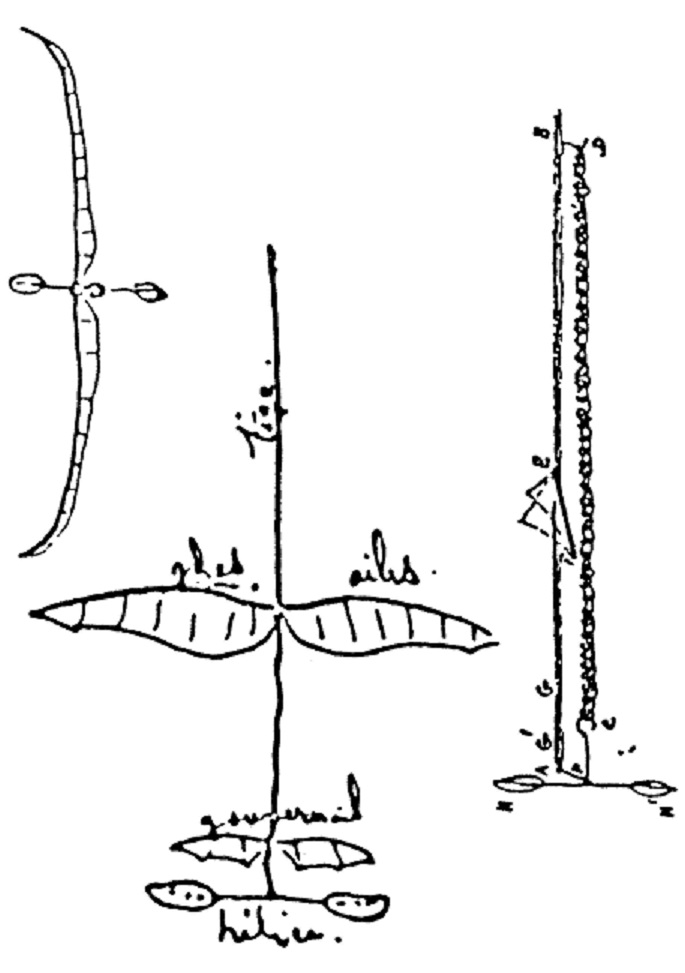
Penaud used a two blade propeller. The propeller shown in L’Aeronaute is an extended figure 8. It is a schematic symbol rather than an engineering drawing. The only other authentic drawing I know of is Penaud’s sketch in his letter to Bennett, which shows paddle blades at the ends of long sticks. The proportions are different in each of the three views. Most of the various drawings show something that looks like a Pennyplane propeller, with oval or tear drop shaped paddle blades on the ends of sticks. The inner vortex comes off the blade about 20% out from the hub anyway, so the blade does not need to continue all the way to the hub. It doesn’t do anything along there except connect the blade to the hub, so make it a small stick to reduce drag. The Hannan, Perham and Magrath models all use something like that. Some look like they were cut from feathers. There is no indication of twist. Lack of twist is consistent with blades at the ends of long sticks, because most of the twist is near the center of the prop. The outer portion is much less twisted, so a flat blade is not as bad if it is closer to the tip. Penauds blades have a higher aspect ratio than most of the other drawings. The helicopter blades shown in Fig. 1 would be a reasonable choice.
There is no evidence that the blades had cambered airfoils. His rotation loss test suggests that they were perfectly flat, no camber and no twist.
Nothing is said about the angle of the blades to the plane of rotation. The diameter is 21 centimeters and the pitch is 32 centimeters, giving a pitch to diameter ratio of 1.52. If we knew the reference radius for the pitch, we could calculate a blade angle. If the pitch was at the tip, the blade angle would be 25.9 degrees. With an advance ratio of 1.25 as calculated above, for the blade angle at a reference radius of 70% to be at an efficient 5 degree attack angle, the blade should be at 35 degrees. That makes a lot of unwarranted assumptions, but may be a good place to start. An advance ratio of 1.25 implies and advance angle at the tip of 21.7 degrees and an attack angle of 4.2 degrees relative to the blade angle calculated from the pitch to diameter ratio. These small, flat blades probably need a bit more attack angle than that, so 25.9 degrees might be as low as you would want to set your prop at the tip. A Pennyplane prop allows rotation of the blade spars in the hollow tube hub so adjustments can be made.
Adding a little camber and proper twist to the propeller blades could significantly improve the propeller efficiency and the performance of the Planophore.
Nothing definite is known about the attachment of the shaft to the prop hub or the bearing. It has a single bearing point, which suggests the prop could wander if a long motor was used and unwound.
Motor
Both of Penaud’s sketches show a simple hook on the shaft for the motor. The rear motor hook is very shallow, suggesting the motor was fairly tight. The single hole bearing would favor a fairly snug fit for the motor, too.
We know the motor weighed 5 grams and was about 18″ long. A modern rubber motor like that, with a typical density of 0.94 and thickness of 0.042″, would have a cross section of about 0.018 square inches and would be two strands about 0.215″ wide, with a turns capacity of about 1,400, about 7/32″ wide or slightly less than four strands of 1/8″. Today we would be flying an 11 gram airplane on a loop of less than 1/8″ wide rubber, with a turns capacity of more than 1,900 turns. A weight of 11 grams for an airplane of this size is reasonable. Modern rubber, with our better knowledge of lubrication and stretch winding, would make possible flights much longer than those reported for the originals, especially with a bearing and hooks that allowed the motor to be longer than the distance between the hooks.
We know that Penaud put 240 turns into it and it produced 29 gram centimeters of torque at 60 turns. This isn’t enough information to derive any conclusions about the properties of this rubber. The 29 gram centimeters is consistent with an 18″ loop of 1/8″ modern rubber with about twice the number of turns. Modern aeromodeling rubber is much stretchier.
He says that 1 kilogram of rubber, stretched to six times its natural length, will provide 500 kilogram meters of energy. This implies a specific energy of 500 meters, or 1,640 feet. Modern rubber will produce more than twice this amount of energy, although we would stretch it about ten times its natural length to get that. In torsion, he expects to get 130 kilogram meters per kilogram, or only 426 feet of specific energy. We would get almost as much energy in torsion as in elongation, although with proper lubrication and stretch winding.
Wing
The best description of the wing planform and dihedral are the sketches from the letter to Bennett. This shows a pointed bird like wing with six ribs parallel with the stick in each half, divided at the center, as would be necessary to clear the stick and motor when the incidence is set. The tailplane is similarly shaped and divided, with two ribs in each side. The front view shows gradually increasing upturn from beyond mid semispan to the tips. The text says the drawing is exaggerated. The side view shows straight, uncambered ribs. The tailplane is described as being similarly upswept, although the Bennett sketch does not show that.
Note that he gives the wing area as 490 square centimeters and the span as 45 centimeters, which produces an average chord of 10.88 centimeters, very close to the 11 centimeter chord. The 11 centimeter chord is thus the average chord.
I would suggest using a wing mounting that allows you to slide the wing back and forth on the stick. Set the prop shaft and tailplane parallel with the stick and set the wing zero lift incidence at 6 to 8 degrees.
He says goldbeaters skin was used for the covering. So you’ve got to find a goldbeater to skin before you can make an authentic model. The reproductions use tissue paper. Onionskin paper would work, too.
Penaud does not explain the mechanism of the upswept wing tips. He doesn’t discuss the necessary balance between dihedral and fin.
Governor
The tailplane is described as being similar to the wing, but smaller. No dimensions are given. The best we can do is scale from the sketch in the letter to Bennett. The article in L’Aeronaute says its tips were raised, but the Bennett drawing does not show that.
Penaud’s discussion of the function of the tailplane is simplified. Variation in pressure center and lift coefficient with attack angle and downwash were not known at that time, so the analysis could not be complete.
Fin
The L’Aeronaute sketch is ambiguous. What may look like a fin may also be the upturned tips of the tailplane. The text says a fin may be fitted to control turns. The Bennett sketch does not show a fin. The fin would not be required for directional stability, given the pusher prop. Upturned tips of the tailplane would also give directional stability, but that is not shown in the Bennett sketch.
Langley
About 20 years later Professor Langley at the Smithsonian conducted experiments with rubber powered models and concluded “The longest flights obtainable did not exceed 6 or 8 seconds in time, nor 80 to 100 feet in distance, and were not only so brief, but, owing to the spasmodic action of the rubber and other causes, so irregular, that it was extremely difficult to obtain even the imperfect results which were actually deduced from them.”
I can see why Langley couldn’t get any of his rubber models to fly more than 6 seconds, about what you would expect from dropping a piece of paper from launch height. He had the wing at zero incidence and the tailplane at a terrific negative incidence. He misread Penaud’s figure and text. It seems that Langley (or his staff) interpreted Penaud’s drawings as showing the wing parallel with the prop shaft. That is indeed what the drawing Fig. 3 shows. But this also shows the governor parallel with the prop shaft. Close examination of Fig. 2 and reading of the text makes it clear that Penaud intended the tailplane to align with the direction of travel and the prop shaft and that the wing should have an angle of incidence to the direction of flight. Langley’s Planophore reproductions have no camber in the wings. They do have a fin.
Langley’s Memoir on Mechanical Flight makes interesting reading, especially the section “Experiments With Small Models”. He provides a detailed description of his reproduction Planophore and adds some details of construction. He later developed two very successful large steam powered models.
Cayley
George Cayley was Penaud’s predecessor in flight, having built successful gliders and even considered rubber power. His ideas about aerodynamic forces were similar to Penaud’s.
Competition
There will be a Planophore competition at the Southwest Regionals held 18, 19 and 20 January, 2014 near Eloy, AZ. Scroll down to find a link to the rules.
Hi There,
My name is Ben Bowie, I’m a filmmaker engaged on a project about the history of flight for PBS. I’m based in the UK.
I’m interested in Penaud’s role in the development of the airplane and was wondering if you might know any enthusiasts who live here in the UK?
All best
Ben
Ben,
I suggest you post a query to Aeromodeller, http://aero-modeller.com/contact-us/ , or the British Model Flying Association, https://bmfa.org/The-BMFA/Contact-Us . Also other aviation, hobby or historical journals, such as Flight International, https://www.flightglobal.com/contact-us/ .
Gary
Hi Ben,
Don’t know if it is too late but I am in the UK. I have a pretty extensive library of very early aeroplane and model aeroplane stuff…including drawings….all sorts and majoring on kites. The oldest original kites are a set of three Scottish hunting kites from the 1860s. Regarding models…Fairly recently I made the test model for the Japanese TV film about Eilmer of Malmesbury (around 1000ad) that we flew from the control tower at Kemble rather than from the abbey. Not so much into aeromodelling now but I used to design flying machines. Based in Bristol. Look me up as aeropleusticartist on Instagram.