The Academy of Model Aeronautics (AMA) has brought out the second in its series of educational free flight rubber powered model airplanes. As with the Alpha, the intent was to produce a kit that could be assembled quickly without glue or sharp cutting tools in a short time and that would be a credible flyer. This makes it suitable for classroom use. In some respects it is similar to the Alpha; foam flight surfaces, balsa stick, plastic wing clip and propeller assembly. The most obvious difference is that the Beta is bigger.
You may order AMA Betas from the AMA Store or from J&H Aerospace. Teachers may be able to order AMA Betas in bulk at a lower price. Contact the AMA Education Department.
AMA has produced an excellent video to supplement the printed instructions.
The AMA Beta is intended to be part of a STEM program. Therefore my review will have an engineering emphasis.
The Kit
The overall appearance of the Beta is classy. Nice graphics, swept wings, it looks fast. The semielliptical planform is aerodynamically “efficient”, polyhedral is effective for roll stability, adequate tail area provides good longitudinal stability. I am thinking plain white foam would give kids the opportunity to color their own plane with felt pens. The top surfaces are colored. In flight, it is the under surfaces that are visible, so kids still have opportunities to customize their planes. It is always a good idea to have some form of permanent identification on a plane, something like an address sticker.
Propeller Assembly. 6 7/8″ diameter is too small for the wing area it will be pulling along behind it. It might be big enough for the AMA Alpha. I might try it there. It weighs 5.45 grams. The hanger is hard plastic which can’t be bent to give side thrust. At higher torque we might want some right thrust to prevent a right spiral dive. That can be done by shaving a thin wedge off the left side of the stick and gluing it on the opposite side. It has hooks on the sides which can engage a stooge that you must build yourself. It has no built in downthrust, which is unusual. This relates to the wing and tailplane incidence. I like the rectangular wire box to contain the motor. The loose motor came off this hook several times, so I will close the gap a bit more. I am thinking, a triangular box with the ends overlapping. The prop is a copy of the Sig “Hi-Torque” prop. I have always been amused at that name. Somebody at Sig does not understand what we want from a prop. We do not want a prop that requires high torque, we want a prop that develops high thrust from a low torque. That requires a blade airfoil with a high lift to drag ratio, encountering the air at its attack angle of maximum lift to drag. We can’t assess a propeller just by looking at it. It has to be tested in flight and matched to the particular airplane. I put the Sig prop on my pitch gauge.
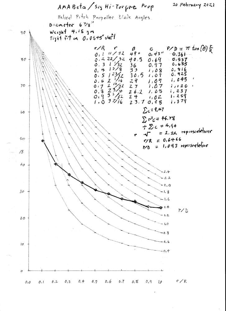
Not a great prop. The background curves are helical blade angle distributions. Not even close. The inner point is actually on the hub and not driving. The rest of them are almost linear, what you would get from a can formed prop. We don’t have any way of knowing where the vortex comes off the inner tip. Properly hand carved props can be much better. I have not done flight performance tests on this prop, but similar props show a large portion of the blade is stalled while the tips may actually be pushing backwards. It is amazing that these props fly our planes at all. Wonder what they could do with a proper prop.
The stuff under the table calculates the representative radius. Each chord is weighed by the square of radius, all summed and divided by the sum of the chords, square root of that is the representative radius. Interpolation gives the representative P/D, which in this case is meaningless, because the values range from 0.537 to 1.379. A P/D of 1.093 is, well, when I go to the shoe store I don’t even look at the size 4 shoes. Unfortunately there do not seem to be any commercially available plastic props that are better.
Stick. The 21 7/8″ stick wood is light, about 7#. This is good for someone who knows how to handle light balsa, it may be too fragile for those who are not familiar with soft balsa wood. As it turned out, my stick broke, as I will describe later in the trimming report. Balsa density will vary. There should be a specification. Hard to know what would be best, but I think 9# would be safer without being too heavy. This example has a vertical slot through the center for the fin. This weakens the stick, fortunately not in a place that is likely to take a lot of stress. The instructions say to stick the fin to the side of the stick with the double sided tape. I elected to put the fin in the slot without removing the protective strip. The rear motor hook is fixed in place, as it must be in a production model. I would have put the hook farther back.
Rubber. The kit included 78 1/8″ of 1/8″ and 77 1/2″ of 3/16″ rubber strip. Enough for several motors. Given the size and weight of this plane, I think a loop of the 1/8″ will be barely adequate. It will be safe for flying in small parks. But you will likely be landing with a lot of unused turns on the motor.
Wing Saddle. At 6.0 grams, this is the single heaviest part of the airplane. Injection molded parts are very dense, so should be kept to a minimum. Fortunately it is close to the CG, so does not unduly affect the CG. For a snap together plane, it is impossible to do away with something like this. Lightening holes are nice. The wing does not need to be up on a pylon. The wing could be right down on top of the stick. Having the wing on a pylon not only makes the pylon unnecessarily heavy, it raises the center of resistance above the center of thrust, producing an up pitch moment. This makes it difficult to achieve longitudinal trim over the full range of motor torque. At high torque and high thrust, the up pitch is strong. Whatever you do to correct that up pitch will be too strong when the torque winds down and will cause a dive. When you correct the dive, the stall will return. The saddle gives the wing an incidence of 1.22 degrees. Considering that the prop shaft has zero incidence, that means this is the attack angle of the wing. This wing must be flown at a much higher attack angle to develop the minimum sink factor required for best duration, as will be reported later in the Flight Test section of this review. The saddle grips the stick well. The gap into which the wing must be inserted is 0.031″ wide. It was very difficult to get the 0.085″ thick wing root into the slot without buckling the wing root. The instructions should say to grip the wing as close to the root as possible when inserting, to reduce the chance of buckling. The wing root is where the bending moment on the wing is maximum. Maintaining strength here is critical. I measured the crushed portions of the wing root at 0.040″ thick. This suggests a relationship between the wing thickness and the gap in the saddle. They should differ by about 0.01″. Or the ratio should be 4/3. The wing saddle is slanted on the front leading edge and I also noticed a small molded in arrow pointing forward. It is important to get the front of the wing at the front of the saddle to get the proper wing incidence angle. There is no dihedral in the saddle. Flight tests suggest some dihedral here would be beneficial. The plane will fly in a steep left bank, which wastes energy.
Wing. The wing area is 64 square inches, indicating a minimum prop diameter of 8″. I could see at a glance at the picture on the box that the prop was too small. Span flat 21 1/4″. With dihedral angles, the span is about 20″. Average chord 3″, aspect ratio 7.04. Foam is 0.085″ thick. The root airfoil is a 13 1/8″ radius arc. This is a good type airfoil for duration, but it has only 1% camber. We really want more camber, more like 5%. Not only would this give a much lower sinking speed, it would also have greater bending stiffness.
Rear Motor Hook. The rear motor hook is permanently installed on the stick, as needs to be for this kind of kit. I would have put it farther back, because more motor length means more turns and more time. I may replace it later, as I did on one of my Alphas.
Fin. Nice shape, matches the wing, very racy looking. The fin had a strip of double sided tape on it. There is a slot in the fuselage. The fin is a snug fit in the slot, so I inserted it in the slot. The subfin might get abraded when landing on rough surfaces, so it might be a good idea to protect it with some tape. I put two layers of clear cellophane tape about 1″ long on the bottom of the fin.
Tailplane. 10 5/8″ span, 20.73 square inches, 5.7 aspect ratio. Incidence is – 2.547 degrees. Quite a bit, especially considering that there will also be 3 to 4 degrees of downwash. There is no down thrust on the prop shaft, so this angle is even greater than usual. The tailplane weighs 3.05 grams. Based on the density of the wing panels and area of the tailplane, I estimate the tailplane foam to weigh 1.36 grams. That means the mount weighs 1.69 grams, 55% of the total. Injection molded plastic is very dense. It is not good when the fixture weighs more than the functional part, especially this far from the CG. It would be better to do away with this part. The dihedral tips are puzzling. I can’t think of any reason for them. 3.1% circular arc camber airfoil. More camber than the wing is not good, we want a lower lift coefficient slope on the tail than the wing. The lower aspect ratio of the tail helps with that.
Assembly and Flying Instructions.
Watch the video with Joshua Finn. Watch the AMA video.
Main Wing Assembly. Leading edge of pylon is swept back and there is an arrow molded into the plastic pointing forward. The pylon must go on top of the stick, the rear motor hook is on the bottom. There should be a picture showing these, as on the AMA Alpha instruction sheet. It was very difficult to get the 0.085″ thick wings into the 0.031″ slot without buckling the wing root. Once the foam is buckled, it is shot. It is necessary to grip the wing very close to the root to reduce the likelihood of buckling. Fortunately the slight camber gives it some strength. It is a good idea to insert and remove each wing half individually before connecting both wings, to slightly compress the ends of the wings for safer installation.
In the AMA video Terry Dunn shows how to use a paperclip to ease the wings into place.
Horizontal Stabilizer. This goes on top of the stick, opposite the side with the rear motor hook. It must be oriented in the correct way fore and aft. The sweep goes in front and the elevator tabs go in back. The picture helps, as always.
Vertical Stabilizer. This says the horizontal stabilizer has double sided tape. It does not. My fin had the tape, but it fit snugly into the slot in the fuselage stick, so I left it friction fit and did not peel off the protective cover. You must be careful when inserting it to hold it close to the slot to prevent buckling. Note that the rudder tab must clear the top of the stick. The bottom of the fin can be reinforced with tape, since it will drag on the ground.
The Propeller. The propeller box was too small to fit on the stick. I pressed the front edges of the stick against the table top to form a slight taper, but even that wasn’t quite enough. It took considerable force to get the prop assembly onto the stick. Once I got it started, I put the box down on the edge of the table and grabbed the stick with both hands, close to the end, and pushed it in. There is danger that holding the stick some distance away from the prop while forcing it will cause the stick to buckle and break. This trimmed about 1/32″ off the top of the stick with only slight compression at the sides and bottom.
You may want to balance your prop and put a tiny drop of light machine oil on the prop shaft.
Trimming and Center of Gravity. It is improper to trim with control surfaces. If you need to do that, there is something wrong with the fundamentals. Using control surfaces to correct fundamentals simply wastes more energy, reducing duration. Control surfaces can be used to teach about the effects of control surfaces, they should not be used to correct bad trim. This teaches bad practice. I decided to set up with a 15″ loop of 1/8″ rubber for the motor, just because I had one on hand. I balanced to find the CG of the fuselage assembly, with the motor doubled between the hooks to keep it in place. I marked the wing root chords at 1/3, per the instructions. I put the wing on the stick with the 1/3 marks over the fuselage CG, expecting to make small adjustments. The wing needed to be moved back. I gripped the stick with one hand and tried to move the wing with the other. The stick snapped between my fingers, behind the wing, from the pressure of the grip. I was able to glue it back together. Eventually I got it to balance at the 1/3 chord, at 31 mm, with the 1/3 mark 1/2″ behind the fuselage CG. No, you do not want to bend the elevators down to correct a stall. The stall is from a misplaced CG; move the wing aft.
Others have found the plane flies better with the CG farther back on the wing. The low camber and low incidence favor a more aft CG. Terry Dunn recommends putting the CG at the fourth lightening hole in the pylon. Doyle Blevins puts his CG 70 mm back from the leading edge, near the back of the fourth hole. My tests so far favor a CG 2 3/8″ from the leading edge, 60.325 mm, at the front of the fourth lightening hole. These are pretty close to the same thing.
Winding Stooge. Refers to the red front bearing. Mine is black. The color is not important. The best stooge is a capable friend. See my Foot Stooge.
Winding Tips. It is a good idea to use a 1/8″ O-ring at the knot end of the motor to ease getting the tightly wound, lubed motor off the winder and onto the airplane. 800 turns on 1/8″ won’t do it. The discussion of back off winding is wholly inadequate. It is perhaps out of place for a beginner model. It requires a more sophisticated understanding of rubber energy storage, the relationship between the winding curve and the unwinding curve and the relationship between the torque curve and flight performance. You don’t keep turns at a maximum by backing off from the maximum. That statement is going to confuse people. An alternative to backing off is to stretch the motor a little and relax it. The same is accomplished by not coming in all the way as you wind, but holding turns count as you come in the last length. These are three equivalent ways to manage the hysteresis effects of rubber energy. This is even more complicated to explain, because it combines torsional energy and extensional energy. No, you do not want to make the 3/16″ motor shorter. It will already take fewer turns per inch. You want all your motors as long as you can get them, subject to your ability to manage very long motors. Beyond about twice the hook distance, longer motors get very difficult to manage. The propeller in the diagram is garbled, should be redrawn. The rear motor hook should be shown here.
Joshua Finn shows the assembly in a video. Later in that video, Caleb gets off a spectacular flight.
Flight Testing
We test fly with the wing in different positions along the stick to find the CG location on the wing which produces the best flight. Ideally this would be done in perfectly still air, but since this is never found in open air we must rely on judgement rather than precise measurements.
18. February, 2021 – The weather forecast called for 1 mph winds and no rain for several hours early Thursday morning. I got my entire test flight kit together, everything for motor torque and propeller testing, and headed over to Butcher Park. There is a square soccer practice field that is about 400 feet on a side, with tall trees all around the perimeter and tract housing outside. I brought a TV dinner table to support my equipment because I knew the grass would still be wet from rain. Arrived at 8:30 AM, could detect a very slight, variable drift. The motor is a 15″ loop of 1/8″, braided and lubed. I used my foot stooge for stretch winding.
1,000 turns, descending 1/4 left circle. That is the equivalent of 800 turns on a 12″ motor, not going to fly. Trim was good, steady flight.
1,200 turns, descending 1/4 circle, no climb, most turns still on the motor at landing.
Without rewinding, raised the leading edge 1/16″, not as bad. Raised again, even better. Raised to bottom of tab, 1/4″, it wants to fly. That puts the wing at about 5 degrees to the thrust line, which is about what I would expect for this airfoil. Maybe more would be even better.
1,200 turns, 1 1/2 circle, 21.42 seconds. Trim was good, steady flight. About 40 foot left circle.
Relubed the motor, it broke at 950 turns.
18″ loop of 1/8″, broke at 1,550 turns. Motor should have been broken in. Maybe I was winding too fast. Calm down.
Another 18″ loop of 1/8″, 1,200 turns, 1/4 circle, 9.01 seconds.
1,500 turns, 1 3/8 circle, 16.14 seconds.
1,550 turns, 2 3/8 circle, well overhead, but not high, 32.90 seconds. Drifted most of the way across the field.
Preparing to put in 1,600 turns, felt the wind on my face, prop spinning rapidly in the wind. Thinking about where it might drift if I go for a minute. Reluctantly decided to not risk losing my new plane in the trees. Went home at 9:45 AM.
Nine flights. Last flight wasn’t long, but very satisfying to see it circling overhead. I didn’t get to do the testing required to size the motor or evaluate the prop performance.
Weather forecast shows stormy weather for several days. Flight testing must wait. Until then, there are a couple things I can do in the shop.
22. March, 2021 – The weather forecast for this morning was for 2 mph wind. I packed my equipment and the Beta and headed for Butcher Park with a 400′ x 400′ lawn. Arrived at 7:30 AM.
There was frost on the ground, 38 Fahrenheit, enough drift to spin the prop slowly. I had put six marks on the stick, starting at 4 7/8″ and going in 1/2″ steps to 7 3/8″. The last would put the CG with motor at the 1/3 chord position, per the instructions. I already knew from past experience and Internet discussions that this was not a good location. The first would put it where Doyle Blevins recommended.
Wing at 7 3/8″, sixth position, 17″ loop of 1/8″.
1,550 turns, bad launch, relaunched, ~1/4 circle, 2.9 seconds, not near enough power.
17″ loop of 3/16″.
1,000 turns, 1/8 circle, 1.65 second, left into the ground. There is not enough dihedral. Launching without rewinding, wing moved forward, doesn’t want to fly until in position 3, 2, 1. Tight left circle, steep left bank.
Added one thickness of right rudder.
1,000 turns, 3/4 circle, 5.58 seconds. Relaunch with 2X rudder, long wide circle, slightly stalling, into tree at far end of field, about 15 feet up. Safe recovery with pole.
Wing at second mark, rudder at one thickness.
1,000 turns, 2 circles, good steady flight, 37.85 seconds, about 20 feet high. Motor knots jammed at both ends, prop stopped.
Wind in face, spins prop rapidly, stopped flying at 8:28 AM.
CG with wing at 5 3/8″, 17″ loop of 3/16″, is 1 3/8″ from trailing edge, 2 3/8″ (60.325 mm) from leading edge, 63 1/3% of root chord, at the front of the 4th lightening hole in the pylon.
Videos
There are several YouTube videos of Betas flying, in addition to the ones above by Hope and Joshua Finn and the AMA. Read the comments below the video to get the most information. We are still working out the best position for the wing.
Bill Kuhl flies on a frozen lake.
Doyle Blevins flies in a gym.
Not quite sure what is rubber band “hysterisis” other than the specs for speakers.
When you wind up a rubber band, the torque increases along a certain curve. When the rubber unwinds, the torque follows a lower curve. The area between the curves represents lost energy. This is known as hysteresis loss.