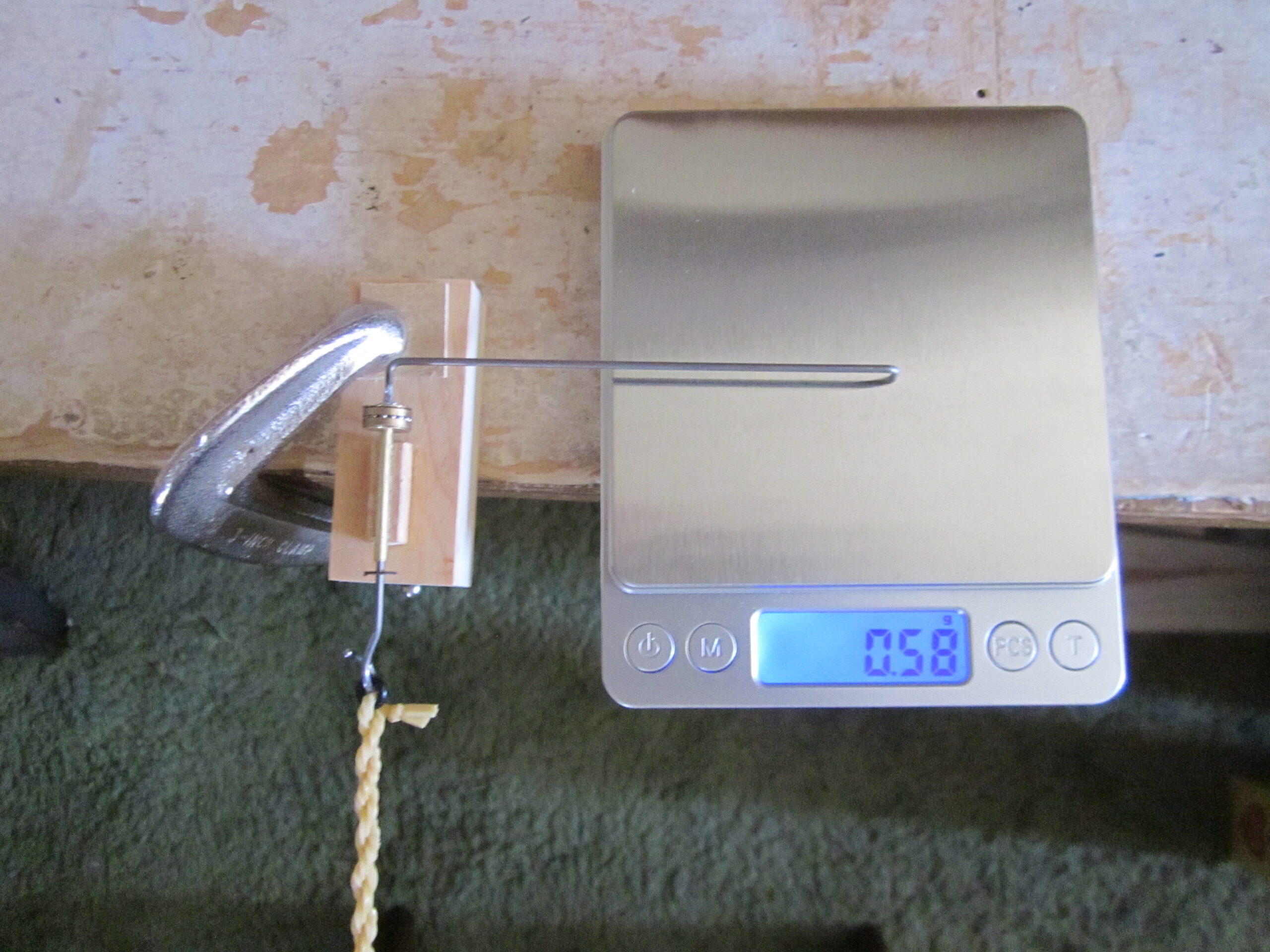
After finding that the available wire torquemeters were inadequate for my purposes, and suitable wire was unavailable, I decided to try something different. One of the guys had a digital torquemeter which he had from FAI, no longer available. Also, two years ago one of the students had a little blue plastic box with a hook sticking out of it, a couple buttons and a display. I don’t know where he got it. There is a place where you can download files to 3D print the box and install your own mechanicals and electronics, but I don’t have a 3D printer. So I had to make do with what I had.
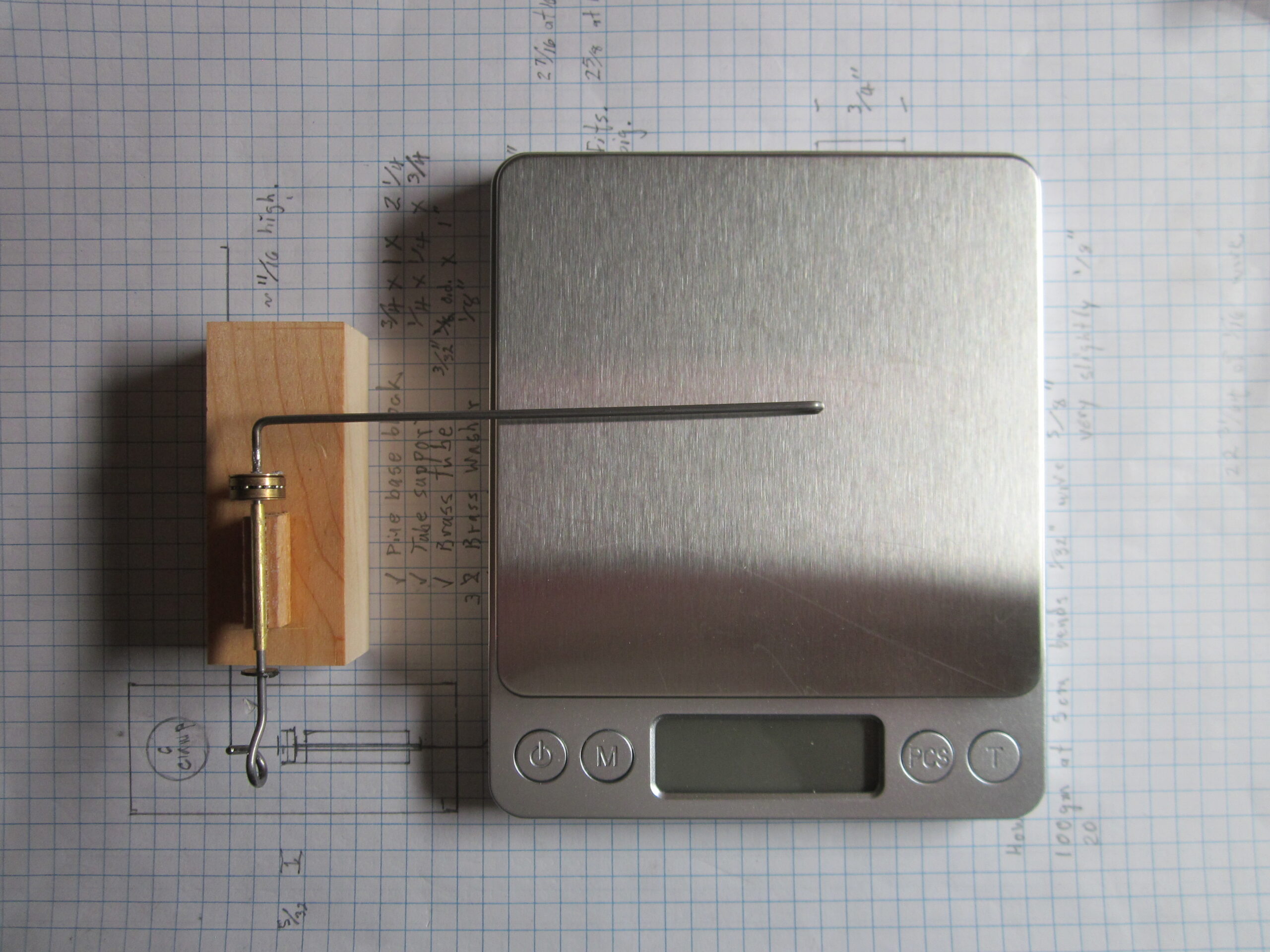
In use, the base block is clamped to the table with a 3-inch C clamp. A smaller clamp might work, but this is what I had. I protect the pine base block with a 3/4″ square of 1/16″ ply to keep the C-clamp from denting the block. (Not shown)
Parts List:
1 Pine base block, 3/4″ x 1″ x 2 1/2″
1 Bearing tube support, 1/4″ x 1/4″ x 3/4″ pine
1 Brass tube bearing, 3/32″ dia x 1″
2 Brass washers, cut from 0.010″ sheet, 1/16″ id, 3/8″ od, hand made
1 Ball bearing, 3/8″ diameter, 1/8″ thick
1 Hook and arm, 1/16″ steel wire, ~7 3/8″ long
1 Retainer disk, 0.0215″ HDPE peanut can lid, 1/16″ id, 1/4″ od, hand made
1 Base protector, 1/16″ x 3/4″ sq ply (Not shown)
1 3″ C-clamp (Not shown)
The suitable digital scales are about 3/4″ thick, so I used 3/4″ pine for the base to even it up. I originally considered 1/16″ brass tube, but the 1/32″ steel wire that fits will bend too much under load. Next size tube best fit wire is 1/16″. This is tough to bend to shape, but it won’t bend under expected load.
Construction Sequence:
Drill 1/16″ holes along the edge of 0.010″ brass sheet, spaced as far apart and as far from the edge as to allow 3/8″ washers to be made. Insert the 1/16″ steel wire through the bearing and into the brass sheet. Scratch around the 3/8″bearings with a sharp pointed scriber. Cut out the pieces with sheet metal shears, initially in squares which are later cut as close as possible to the scribed lines. Find a small box nail with a 1/16″ shaft. I used two 1/16″ ply disks, 1/4″ in diameter with 1/16″ holes in the centers. Put one ply disk on the nail, next the washer blank, last the remaining ply disk. Insert the nail into an electric drill or Dremel chuck, press it in and snug up the chuck. Lightly tap the nail and tighten up the chuck. Turn the drill on and use a fine file, knife sharpener or other tool to grind the high spots down on the washer. There may be a burr forming, grind it down. Finish with 500 grit wet/dry sandpaper glued to a block of wood. You will need two for each torquemeter.
Get a HDPE lid from a can of nuts or coffee. Cut across the middle to expose a straight edge. Punch 1/16″ holes along the edge, spaced as far apart and as far from the edge as to allow 1/4″ washers to be made. Center the paper punch 1/4″ hole on the 1/16″ holes and punch out the disk. You will need one for each torquemeter.
Use a jeweler’s round file to file a half 3/32″ groove along the center of one face of the bearing tube support block. Check for a snug fit with the bearing tube.
Glue the bearing support block on the centerline of the base block, 1/4″ in from one end.
The brass washer farthest from the hook must be soldered to the 1/16″ wire shaft. File a small nick in the wire the appropriate distance from what will be the hook end. Drill a 1/16″ hole perpendicular to the face of a small block of wood, about 1/4″ x 1″ x 1″. Slide the block from the hook end up to the nick. Slide a brass washer on from the other end and solder it to the shaft. Scrub the wire with cleanser, wash and dry and tin with solder first.
From the hook end, slide on the ball bearing, second washer, brass tube and HDPE retainer. Now bend the hook. I intended to bend a right handed pigtail, but I see the picture shows it left handed. You may use whatever type of hook you prefer. I might use a square hook on the next one.
Grab the wire with the plier against the soldered washer and bend the arm over at a right angle. Double check and get it right. Bend it so the opening on the hook will be up when in operation. Note the distance from the face of the plier to the centerline of the bent over wire. This is the offset you must use, about 2mm, to get the next bend in exactly the right position. Measure out the length of arm you want and mark it on the wire. Place the plier the offset distance back from the mark and bend the wire down. Cut the wire 1/4″ from the bend. File the end of the wire flat and then file faces on the far and near side to taper it to a chisel point, the face about the width of the markings on the ruler. The finger end may be bent to adjust the distance between the chisel point and the shaft centerline to the exact length you want.
Originally I intended the arm to be 5 cm. This would require multiplying the scale reading in grams by 5 to get gram centimeters of torque. I decided to make the arm 10 cm. This requires multiplying the scale reading by 10 to get torque. It also places the finger closer to the center of the scale. Digital scales can also weigh in ounces, so you can chose and arm length to give torque in inch ounces. We weigh our planes and motors in grams, so I chose gram centimeters as my unit of torque.
Glue the brass tube into the groove in the tube support block, with the hook over the short end of the base block. Adjust the retainer disk to allow a bit of play on the shaft. It should not be tight. This completes the assembly.
In use, the 2026 DTM is clamped to a table with the ply protector between the C-clamp and the base block.