USE OF PROPELLER GAUGES
A propeller’s performance depends on the distribution of blade angles along its radius. The blade angle is the angle which the blade chord makes to the plane of rotation. A propeller blade is like a wing that moves along a helical path. Its motion is a combination of the forward speed of the airplane and the rotational speed of the propeller. The blade angles must be greater than the angle at which it moves through the air to produce lift. The blade angle corresponds to the advance angle, related to the advance ratio, the ratio of forward speed to rotational speed, plus an attack angle. For a propeller to be efficient, each element of the blade must meet the air at the attack angle of maximum lift to drag for its airfoil.
Propellers are classed according to their geometrical pitch, or pitch to diameter ratio. The geometrical pitch is the distance the propeller would move forward in one revolution if it moved through the air like a screw, moving forward along the projection of its chord line, not at an angle to its path through the air. For a fast climb, a low pitch is preferred. For slow climb, cruise and descent, a higher pitch is preferred. For moderate performance in all phases of flight, an intermediate or mixed pitch might be preferred. A prop gauge is used in making this classification. For this limited purpose a prop gauge is often called a pitch gauge and it might be calibrated in pitch to diameter ratio P/D. Often the pitch is measured in one location along the radius.
The blade angle projects forward along one helix. The advance of the propeller through the air goes along another helix. Each helix makes a different angle with the plane of rotation. The blade angle must be higher than the advance angle in order for the blade to have a positive angle of attack. The angle of attack is the difference between the blade angle and the advance angle. We can get an idea of whether our propeller is functioning efficiently if we can measure the attack angle in flight. This can be done because we can measure the blade angle and the advance angle. The advance angle is determined by measuring the revolution rate and the forward speed of the propeller. The blade angle is measured with a prop gauge. The prop gauge is thus an essential instrument in evaluating the performance effectiveness of our propellers in flight.
It is often said that a helical prop, one with a constant pitch, is the ideal. Even with fairly crude measurements you will discover that helical props are a rarity. (Although helical props are not optimal, either.) There are some very strange blade angle distributions, most of them not good.
If we think shimming a 6″ chord wing with a 0.01″ business card is necessary to properly trim a model, we should be paying a lot more attention to our prop blade angles. All of the energy which our model turns into time in the air passes through the propeller.
AN EXAMPLE OF PROPELLER PERFORMANCE EVALUATION
To perform a propeller performance evaluation, it is necessary to measure the advance ratio of the propeller in flight and to measure the blade angles of the propeller along its radius. The advance ratio allows us to calculate the advance angle at each radius. The difference between the blade angle and the advance angle is the attack angle of the blade at that radius. We can judge whether the propeller is operating at a favorable attack angle.
To measure the advance ratio of the propeller in flight, we must measure its revolution rate and its forward speed through the air in horizontal flight. This is fairly easy to do. We put turns into the motor and fly the plane, adjusting the number of turns until we find the number of turns required for the plane to leave our hand, fly a circle and return to our hand at the same altitude above the ground that it left our hand. At the same time, we time the flight in seconds. We count how many turns we put into the motor at launch. When we catch the plane, we immediately stop the prop, then unwind the motor, counting the number of turns remaining. The number of turns put in minus the number of turns remaining is the number of revolutions the propeller made during the flight. That the plane flew fairly level during the flight is an indication that the revolution rate did not vary much. That number divided by the flight time is the revolution rate in revolutions per second. We also measure the diameter of the flight circle. Make several flights and run across to the other side of the circle, placing a marker on the ground directly beneath the airplane as it goes over. Then measure the distance between the marker and the starting location in feet. This must be done in perfectly still air, so the airplane does not drift, easiest to do indoors. The circumference of the circle is π times this diameter. This is the length of the flight path. That number divided by the flight time is the forward velocity of the plane through the air.
n = revolution rate, revolutions per second
v = velocity, feet per second
r = radius along propeller blade to each blade element in feet. Your propeller is likely measured in inches, so remember to divide the inches by 12 to get feet.
γ = advance angle = arctan(v/2πrn)
We use the Greek letter gamma for this. There will be a different advance angle for each radius.
The arctan(x) function is a trigonometric function which is found on scientific pocket calculators. Most computers have a calculator with an arctan function, or you can put your numbers into a spreadsheet which will likely have the arctan function. Check that it produces angles in degrees (not radians or grads).
β = blade angle, in degrees, as measured with the prop gauge
We use the Greek letter beta for this.
The attack angle, alpha, is then
α = β-γ
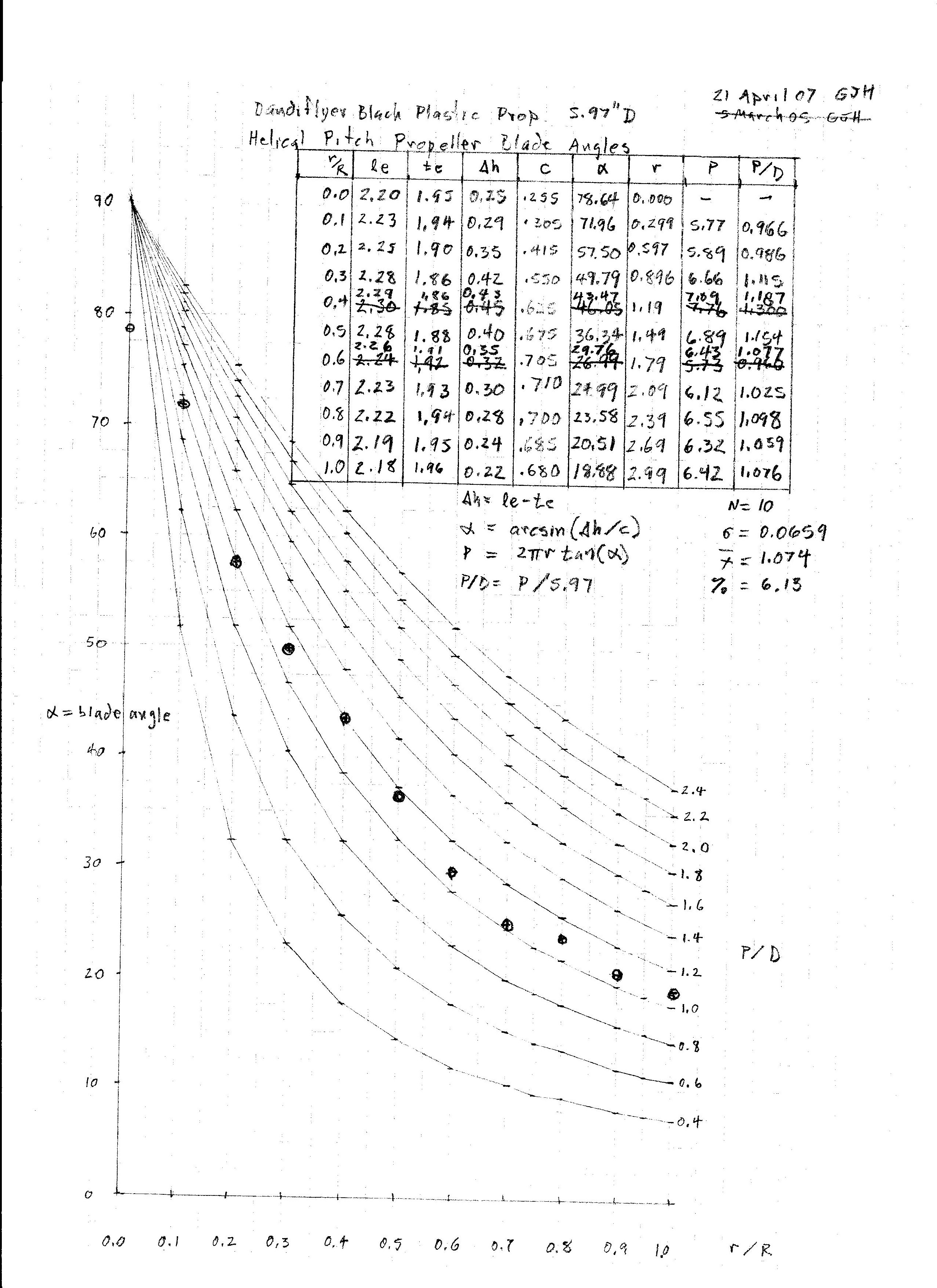
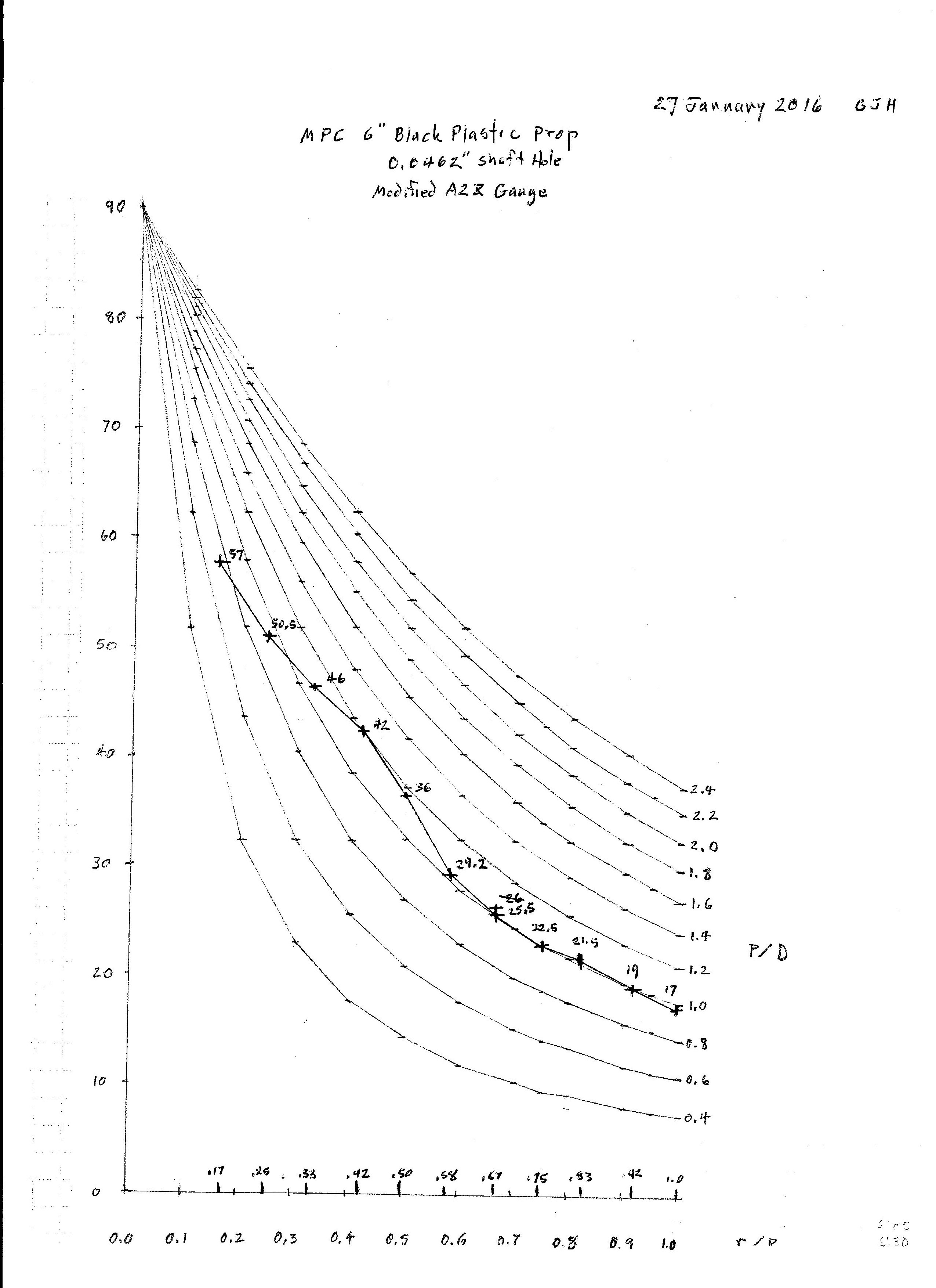
Here is an example of a flight test of an MPC 6″ black plastic propeller flown on a Dandiflyer stick model in a gym.
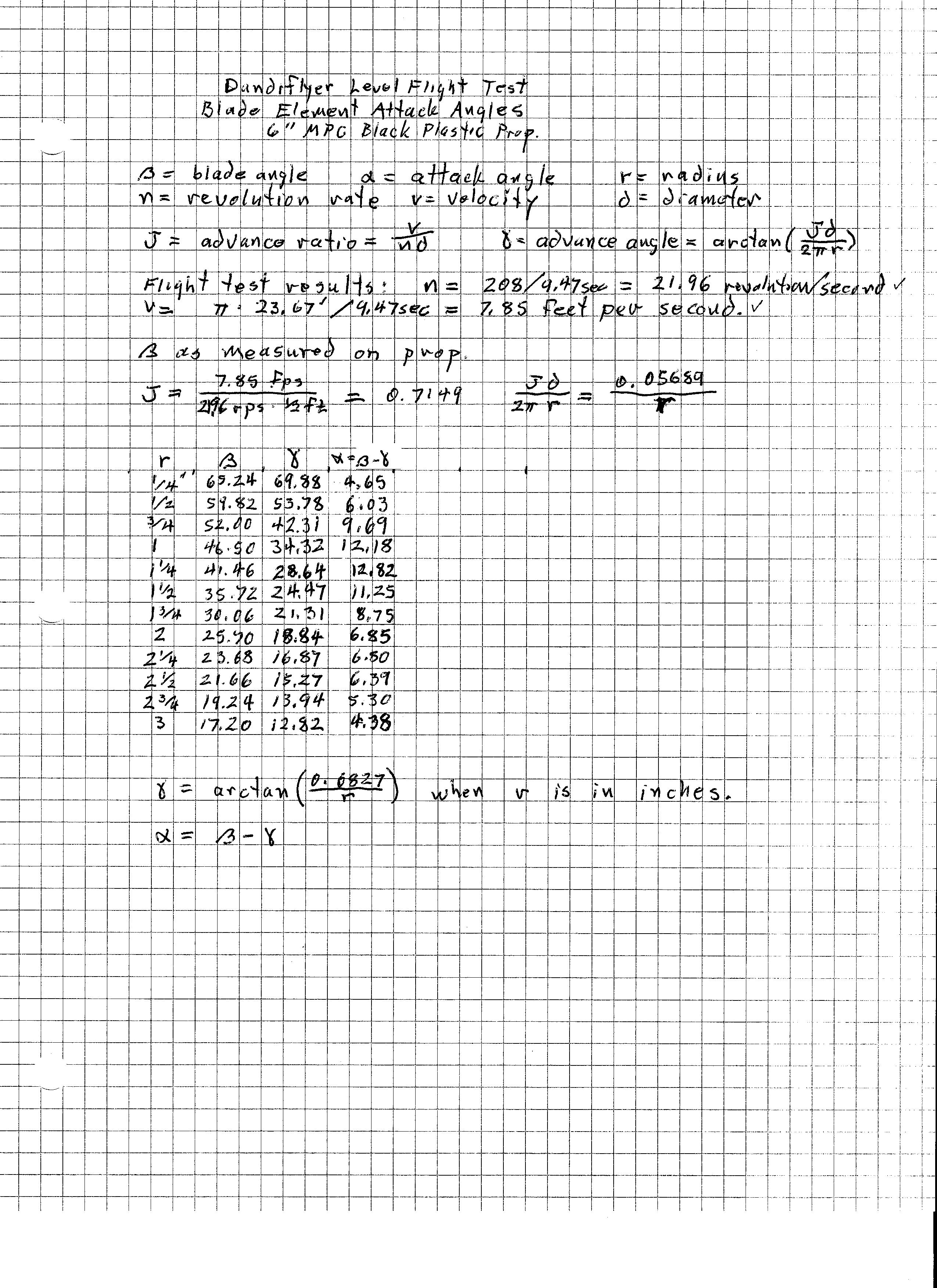
Here is a graph of all three angles plotted against radius.
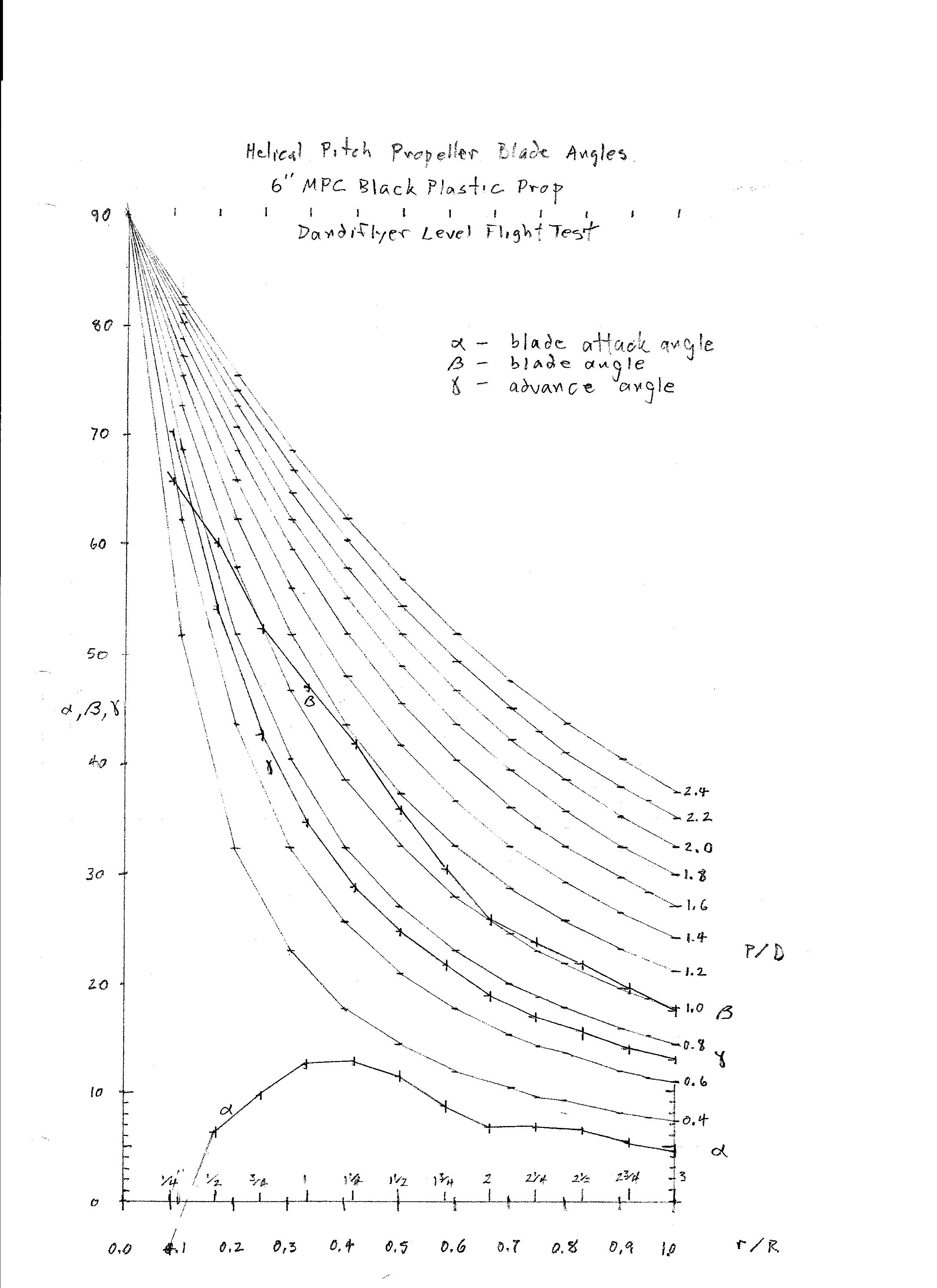
Note that the advance angle curve corresponds to the P/D curve of the advance ratio J = 0.7149. The P/D curves represent the blade angles of constant pitch or helical propellers. This is sometimes described as the ideal blade angle distribution. Many methods for carving propellers aim for this blade angle distribution. You can see that this propeller is not helical. Near the tip it lies along the P/D = 1.0 curve, but below r/R of 2/3 it shows a bulge up to about P/D of 1.2, then comes back to 1.0. The γ curve is of necessity helical. The consequence of this bulge in the β curve is a big bulge in the α curve. The best L/D for these small propeller blades is expected to be at an attack angle of around 4 to 6 degrees. See Small Airfoil Data. You can see that the outer portion of this propeller is flying in this range. Fortunately this is the fastest moving part of the propeller which is doing most of the work. The inner portion of the blade is not performing well, parts of it are likely stalled.
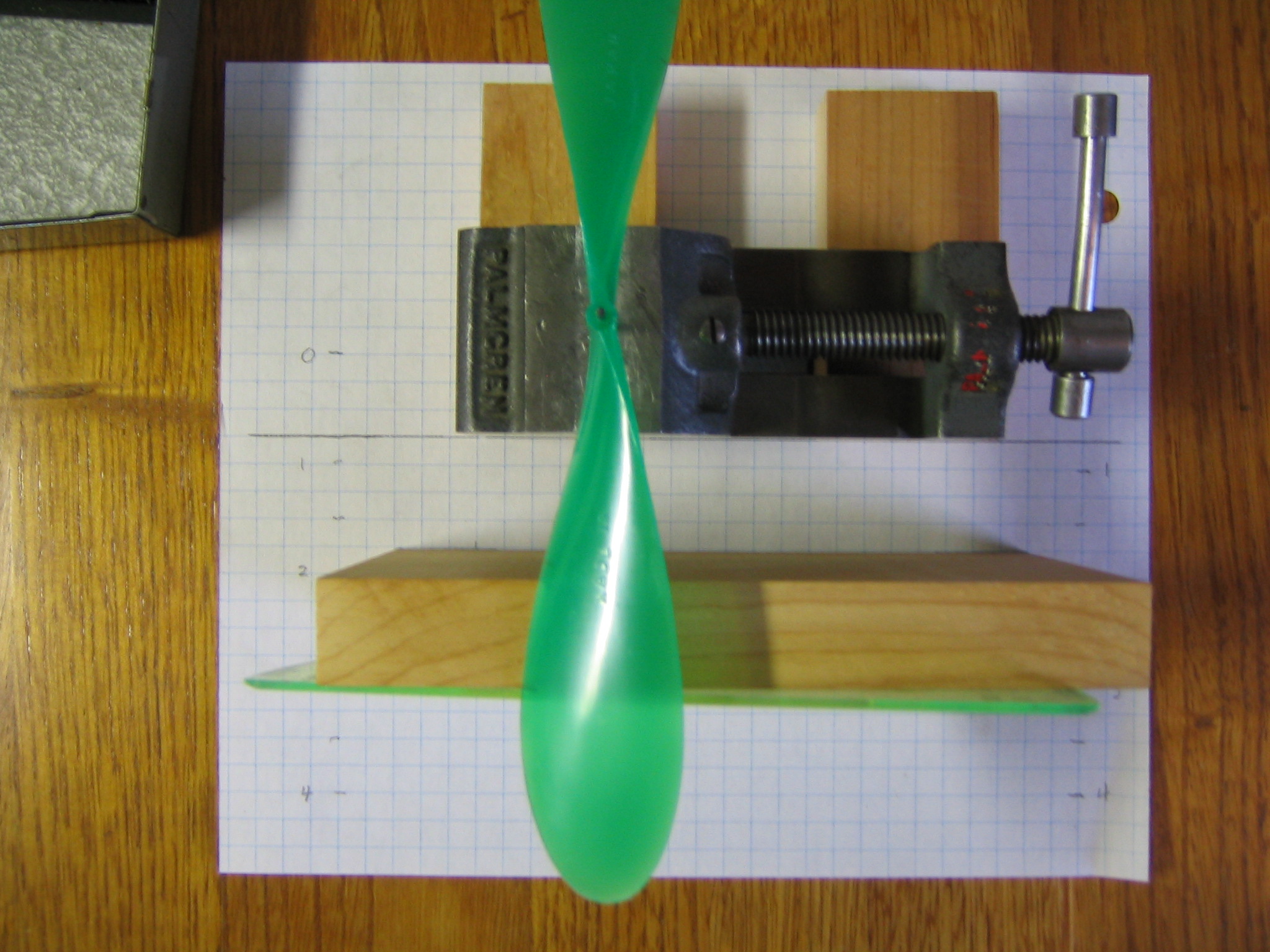
THE CHORD AND OFFSETS METHOD OF MEASURING BLADE ANGLES
Measurements were made at 1/4″ stations along the radius. Small scratches were made on the leading and trailing edges at those stations to locate the chord lines. The prop was rigidly mounted on a vertical shaft. Chord (c), leading edge (LE) offset above table and trailing edge (TE) offset above table were measured to the nearest 0.01″ at each station.
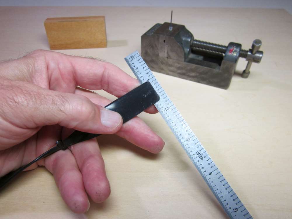
Measuring the chord c.
Measuring the leading edge offset LE.
Measuring the trailing edge offset TE.
Blade angle β was calculated trigonometrically for each radius r. P/D was calculated from the usual formula.
β = arcsin ((LE-TE) / c)
P/D = πtan(β)r/R
The blade angles may be plotted on a graph with helical P/D curves in the background for comparison. In this early graph, I called the blade angle alpha.
Wobbles in the graph may result from measurement precision limitations rather than manufacturing irregularities. The 0.01″ precision corresponds to about 1 degree. I also found that it is important to assure that the prop is rigidly aligned with the shaft and the shaft is rigidly supported in the base. A couple of the points were so far out of line that I remeasured them a couple times to assure myself that the numbers were reliable.
This requires three measurements at each station, compounding errors. The measurements must be very precise. This is very tedious and time consuming.
A similar way is to measure photographs from a straight on front view and square on side view. In that case we would be working with the tangent of the blade angle, otherwise it is very similar. There is a possible parallax problem. Ideally the camera would be at infinity. 😉 These methods work when the leading and trailing edges are sharp and the chord line is clearly defined, as with most of the plastic props. A prop with a rounded nose airfoil could be a problem.
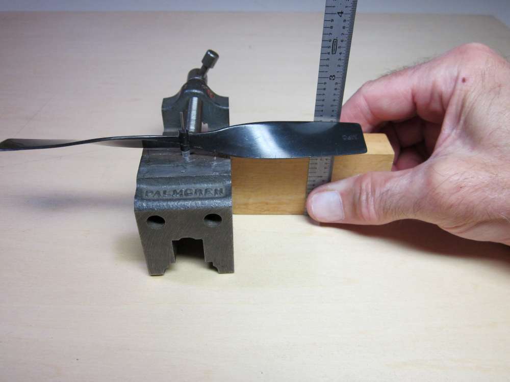
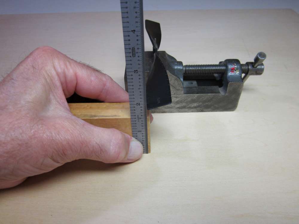
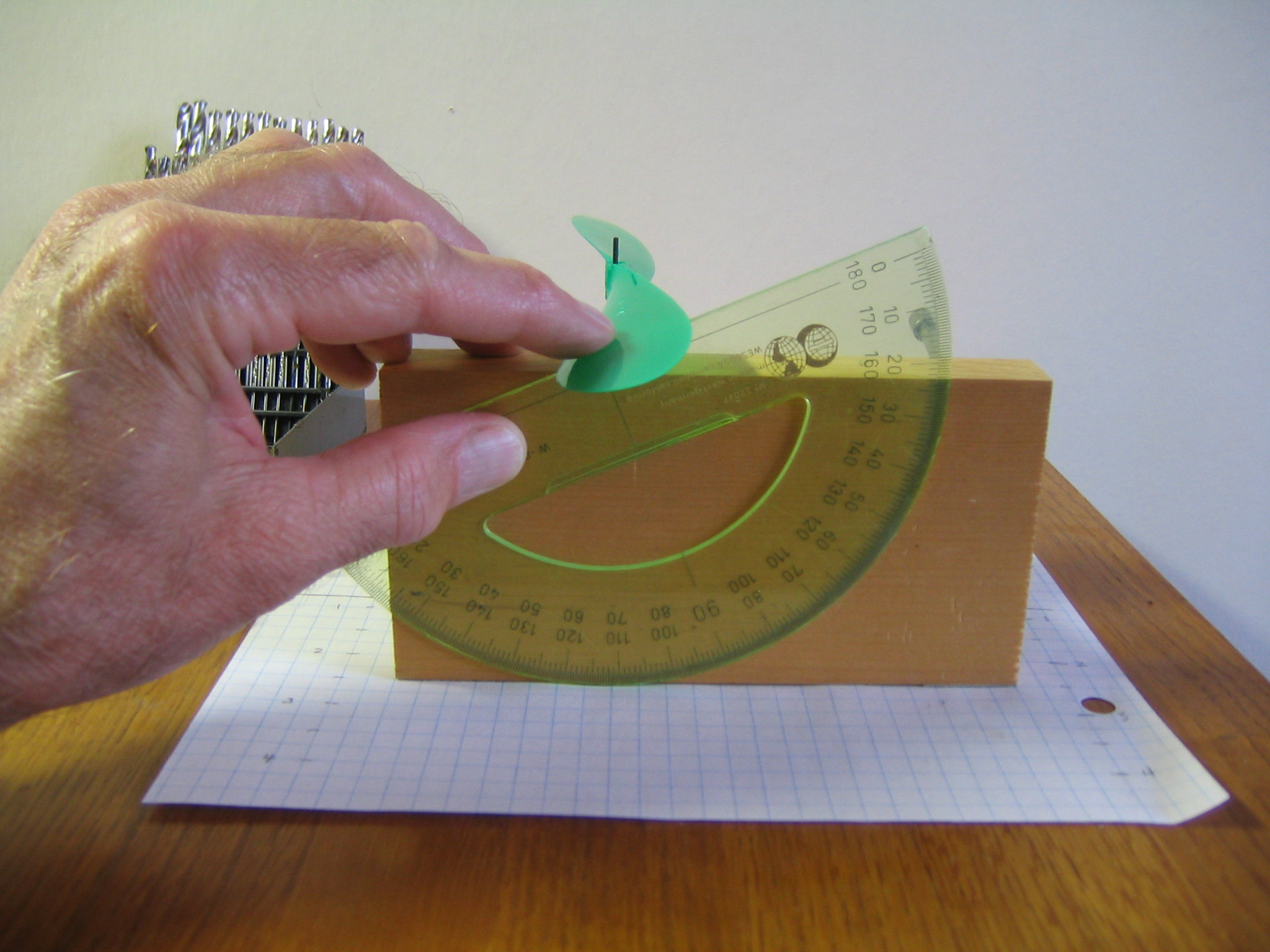
THE PROTRACTOR AND BLOCK METHOD
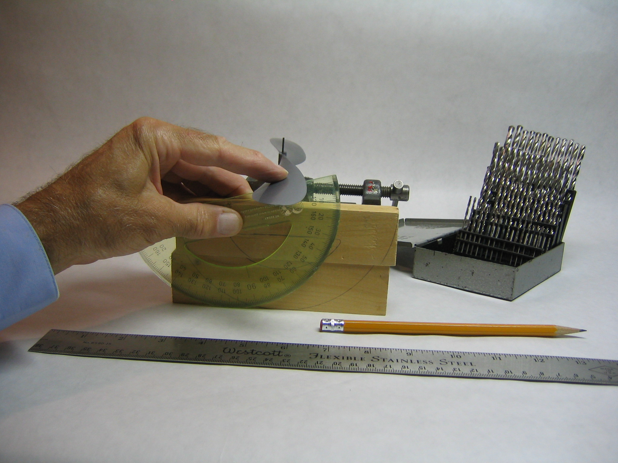
Years ago I devised this method of directly measuring the blade angle. The prop is fit tightly to a steel shaft (drill bit), which sometimes requires wrapping it with tissue for a snug fit, and supported in a vertical V notch in a machinists vise. A protractor aligned with a block of wood measures the angle. The radius of the protractor equals the height of the wood block. The central point of the protractor aligns exactly with the top edge of the block. The angle is read directly off the top edge of the block. Later I replaced the two blocks with a single block and used quad ruled paper on the surface to space the protractor the required radius from the prop shaft. This gives pretty good results, but requires four hands and four eyes to keep everything aligned while rotating and reading the protractor.
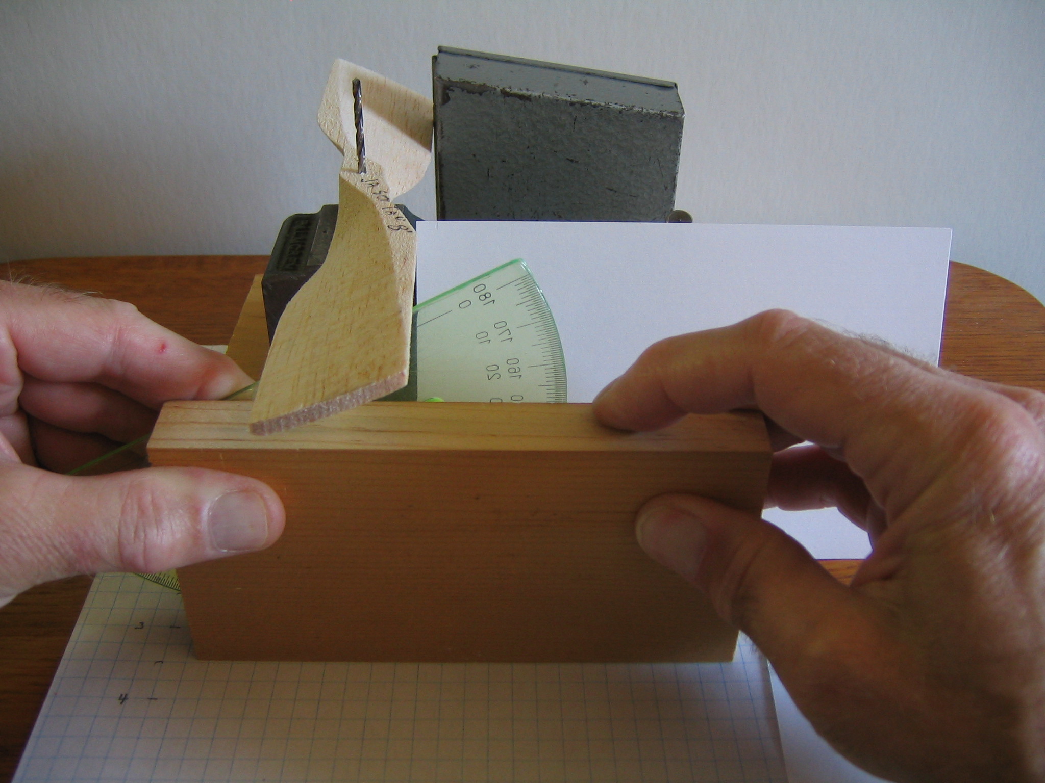
This is an improvement of the method.
Top View.
Front View.
A small machinist vice with a vertical V notch holds a twist drill or steel wire shaft that is a snug fit into the prop. A small bit of balsa stick pressed against the drill keeps it firmly in the apex of the V. A strip of tape wrapped around the shaft or a small plastic disk pushed over it keeps the prop up to the required height. The vice is spaced up from the table on blocks so the prop will clear the horizon block. It is placed so the shaft is over the 0″ line on some 1/4″ quad ruled paper which is on a hard, flat surface. The 3″ horizon block is exactly as high as the center of the 3″ plastic protractor. It is placed so the protractor is at the desired radius from the shaft, as marked on the quad paper. The prop is raised or lowered and the protractor is rotated until it just touches the leading and trailing edges of the prop blade. The angle is read against the top of the horizon block. The 3″ block is held perpendicular and aligned to the station line with the right hand while the protractor is held against the block and aligned to the blade chord with the left. I get my eye down even with the prop when I do that. The angles can be estimated to maybe 0.1 degree, but for pitch plotting, reading to a half degree is good enough.
In this case I got 23.7 degrees at 2.5″ radius on a 7 7/8″ diameter prop. From the formula tan(β) = P/πD we get P/D = πtan(β) = 1.379. At radius 2.5″ the diameter is 5″, so the local pitch is 6.895″. The overall P/D at this radius is therefore 6.895/7.875 = 0.876. Good prop for fast climb, not so good for duration. Actually the pitch will vary along the radius of most plastic props, none are quite helical.
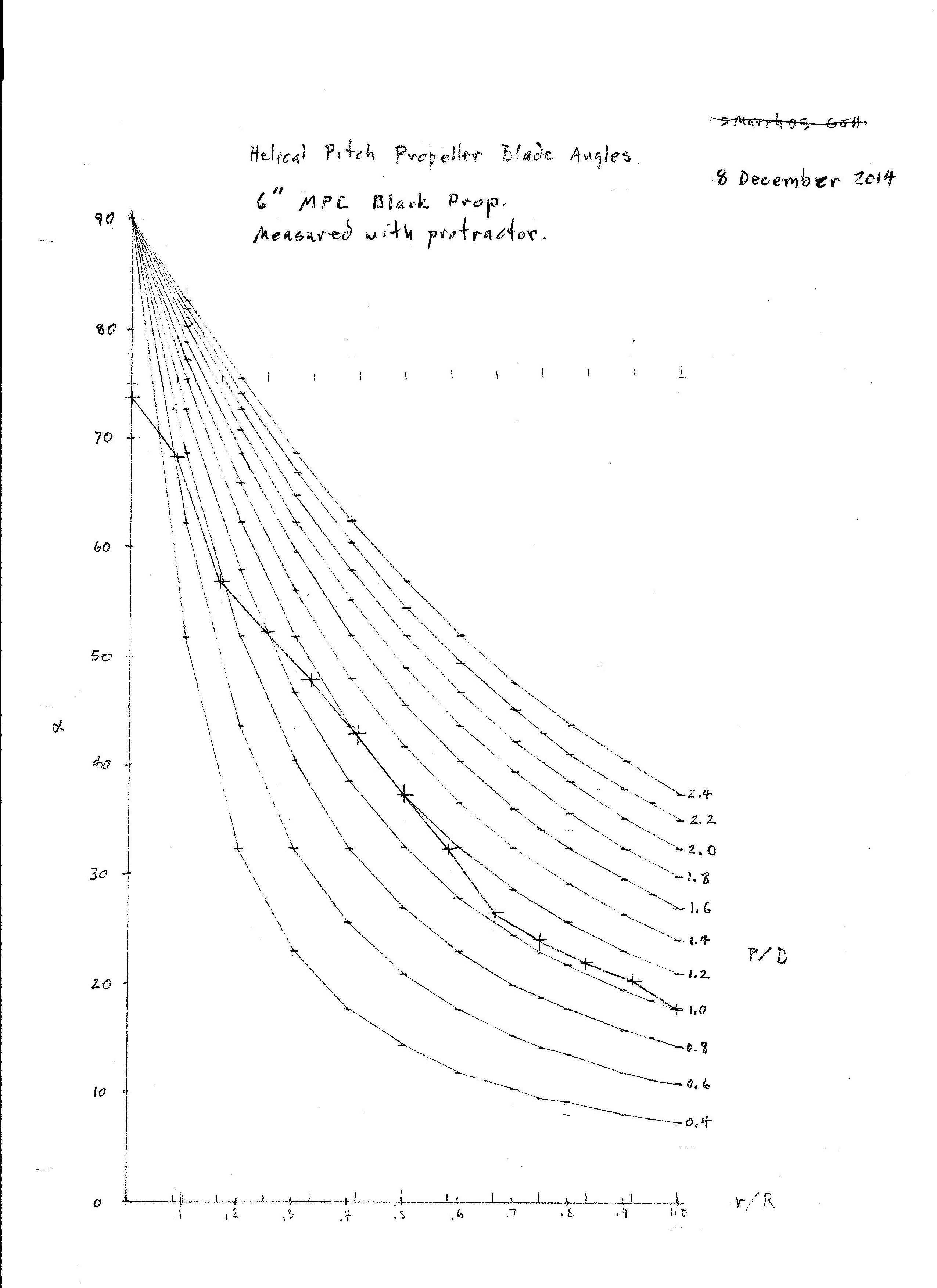
Here is a plot for the MPC 6″ black plastic prop that I have been using as the example throughout this report.
A white index card behind the protractor makes it easier to read. The drill case holds the prop in place.
PROTRACTOR WITH RADIUS ARM
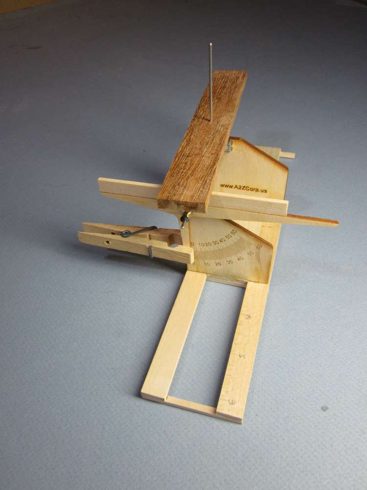
I built a gauge like the one shown at the top of this picture.
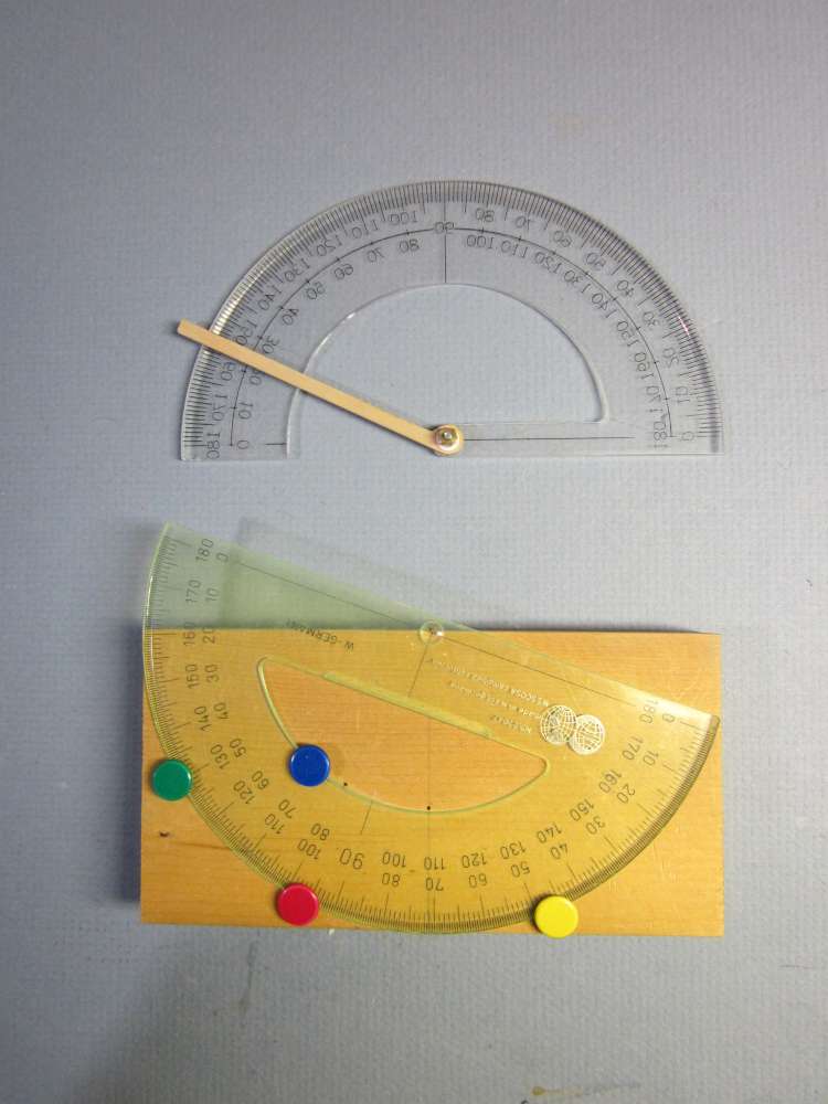
The upper one required raising the gauge on blocks at every station to get the blade chord aligned with the indicator arm. This made it difficult to align exactly with the 1/4″ grid lines. The lower one shows a way of securing the protractor to the block, so it is not always falling down.
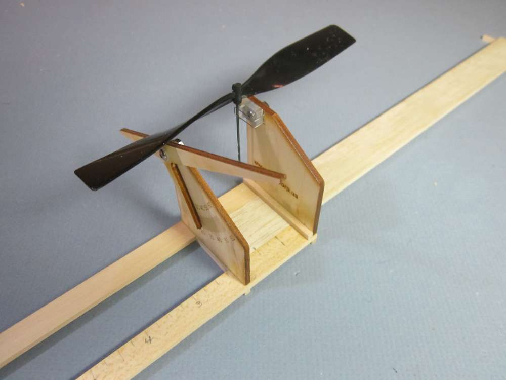
THE A2Z PROPELLER GAUGE
I bought one of the A2Z prop gauges in the going-out-of-business sale. I was very disappointed with it. I was able to rebuild it into a functional gauge. I had seen it before when it was listed at $42.50. I had occasionally improvised pitch gauges, but since I have embarked on a study of propellers, I decided to buy one at the sale price of $25.50, even though it is more limited than what I would need for my present study. It is no longer being manufactured. You might find one on the secondary market, or you may want to upgrade one you already have, as I will show here.
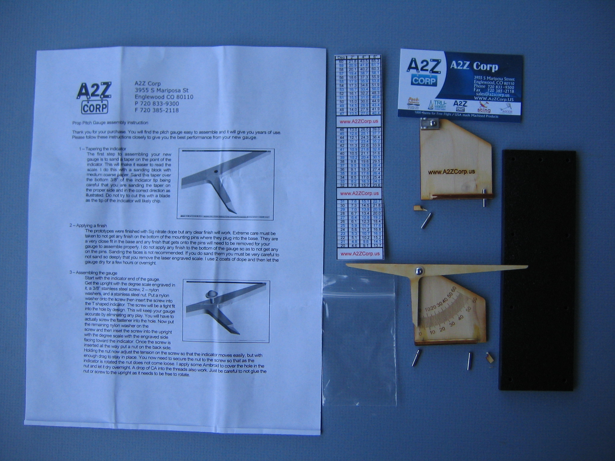
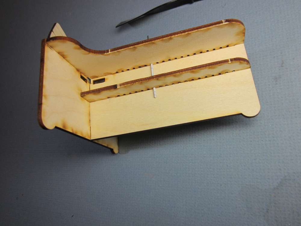
This is a picture of the partially assembled, but broken, components of the pitch gauge. It comes with a sheet of assembly and use instructions, a stick-on angle and pitch table, a vertical back plate with prop holder, a vertical front plate with a protractor and T-bar indicator, and a plastic base plate. I like the fact that the protractor had degree divisions, rather than P/D marks. Each of the vertical plates has a base bar glued across the bottom, with notches that hold steel pins. The steel pins fit into four pairs of holes drilled into the base plate. There are three holes in one end, which is where the back plate should go.
I am carving props for my Cloud Tramp from blocks of wood. I am not making any indoor props. This gauge is for indoor props for things like Mini Stick, EZB and Pennyplane. I have no immediate need for this type of gauge, but I wanted to put it together to see how it worked. If I ever get to teach another class on indoor models, a gauge like this would be useful to have.
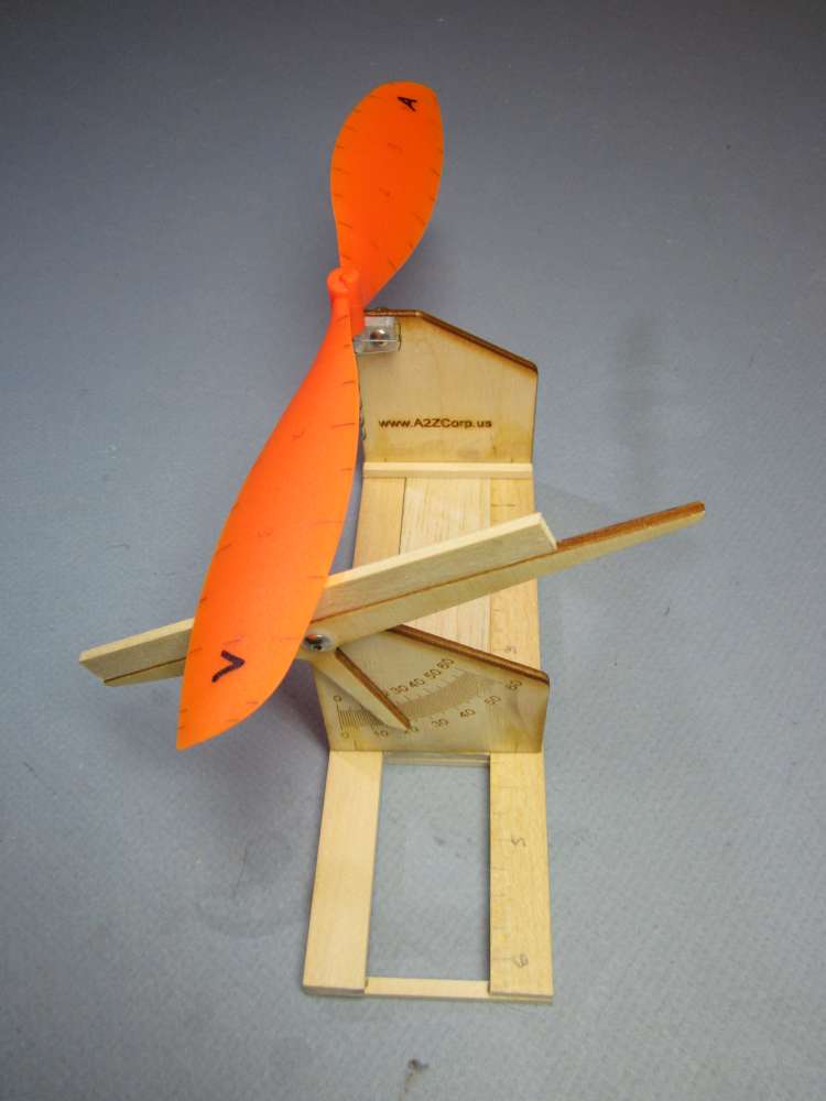
The back plate pins go into the two holes at one end of the base plate. The front plate pins go into one of the other three pairs of holes. These holes are spaced so the indicator will be a nominal 2″, 4″ or 6″ from the prop shaft. The wire prop shaft is clipped into the V notch of the CNC machined prop holder. The prop and T indicator are rotated until the T is aligned with the blade chord and the blade angle is read from the laser etched protractor. The pitch may be read from the supplied table, or you may calculate it with the standard formula.
The base has only three sets of holes, for only three radii. You can’t take blade angle readings at small steps along the radius, unless you drill a bunch of holes, and they must be precisely spaced to match the separation of the pins in the slotted base bar. The protractor radius is about 1 1/2″, so 0.1 degree precision is not possible. Also, it reads only for right handed props.
The instructions said to apply a clear finish to the wood parts. I should have given more thought to the part about not getting finish on the steel pins. Although I skipped applying the finish, this should have been a warning. I should have closely examined the pins.
Both the back plate and front plate came with the slotted base bars and steel pins assembled to the plates with glue. The base bars are cut cross grain from 1/8″ plywood.
The assembly starts with attaching the T indicator to the front plate with a screw, two washers and a hex nut. The narrow indicator arm that points to the protractor is cut cross grain from the 1/8″ plywood. My arm was bent up about 1/32″ from the plane of the rest of the sheet. I didn’t want to try bending it for fear it might break off. This might be less likely to bend if the indicator arm was not so narrow, making it a 45 degree right triangle instead, for example. The plastic washers are about 1/32″ thick, spacing the indicator 1/32″ off the protractor. You must be careful to align your eye perpendicular to the protractor when you read it, to avoid parallax error. The degree markings are about 1/40″ apart, so small displacements of the eye can put your reading off. I replaced the washers with thinner ones made of thin plastic sheet from a cottage cheese carton lid. The screw requires a 1/16″ hex key. If you don’t have one, you can file one from a finishing nail. The screw barely clears the 1/8″ ply at the back of the plate, only two threads are available for the nut. The instructions say to apply CA glue to the screw to keep the nut from coming loose. If it wears and becomes loose, you will need to break the glue to tighten the nut. There could be times when it would be nice to set the gauge at a certain angle and have it stay there.
The 0.015″ wire spring for the prop holder was misshaped, twisted and would not fit in the slot between the V notches. I straightened it out and rebent it. It must be shaped and positioned to hold the prop shaft in the V notches of the holding block. Those building indoor models have experience bending wire and could easily make this part properly from a straight piece of 0.015″ wire. The V notches in the CNC holder block had a significant amount of machining burr in them. It was necessary to remove this burr for a proper fit of the prop shaft into the notches. Gentle application of the corner of a sharpening stone took care of that. Aligning the 0.5″ long block with the 0.5″ laser line is going to be imprecise. I clipped a 4″ length of straight 1/32″ wire into the holder and used a drafting square to align it perpendicular to the base. Roll the wire on a flat surface to be sure it is straight. It should purr, not bark.
Once the two subassemblies are done, the construction is completed by pressing the steel pins into the holes in the base. I found these to be very tight. I had to press down on the tops of the pins with a block of wood to get them to seat. Extruded glue on the bottom of the bar made precise alignment difficult. One of the pins went past the bottom of the plate and stuck out on the other side. Placing this on the table could push one end of that plate up, spoiling alignment. I had placed the indicator plate at the 4″ radius. I measured the distance from the base of the V notch to the adjacent face of the T and found it to be 3.9″. This throws out the calibration of the pitch table. You can still calculate the pitch at that radius from the formula. It is difficult to check alignment of the protractor. Supposedly the 0 degree line will be exactly perpendicular to the base. Again, aligning to a 0.5″ laser mark will be imprecise. The tall edge of the plate would be good, if it is parallel with the 0 degree line. I will tell you later how to set a precise zero.
I wanted to move the indicator plate to the 6″ mark. The pins were very tight in the holes. So tight that the plate came up without the pins. One pin pulled out of the base bar and the base bar at the other end broke away. I pushed the pins out from underneath. Both pins were smeared with glue where they fit into the base. Remember the note about not getting any finish on the pins? I wouldn’t have imagined the manufacturer would have got glue where he cautioned us to not get finish. I scraped the glue off the pins and they were a reasonably snug fit in the holes. Unfortunately one of the pins on the holder plate also broke off an end of its base bar. I planned to soak both base bars off with solvent and replace them with 3/16 hardwood bars. Then I had a better idea.
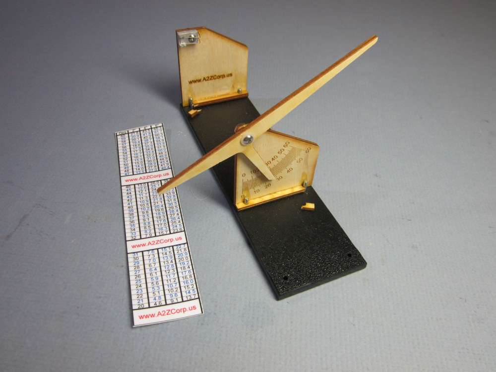
Here it is, assembled with the broken pieces of the base bars.
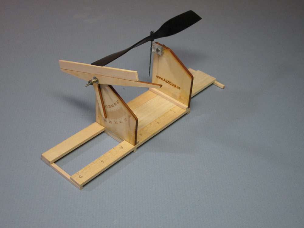
A2Z GAUGE WITH SLIDE RULE BASE
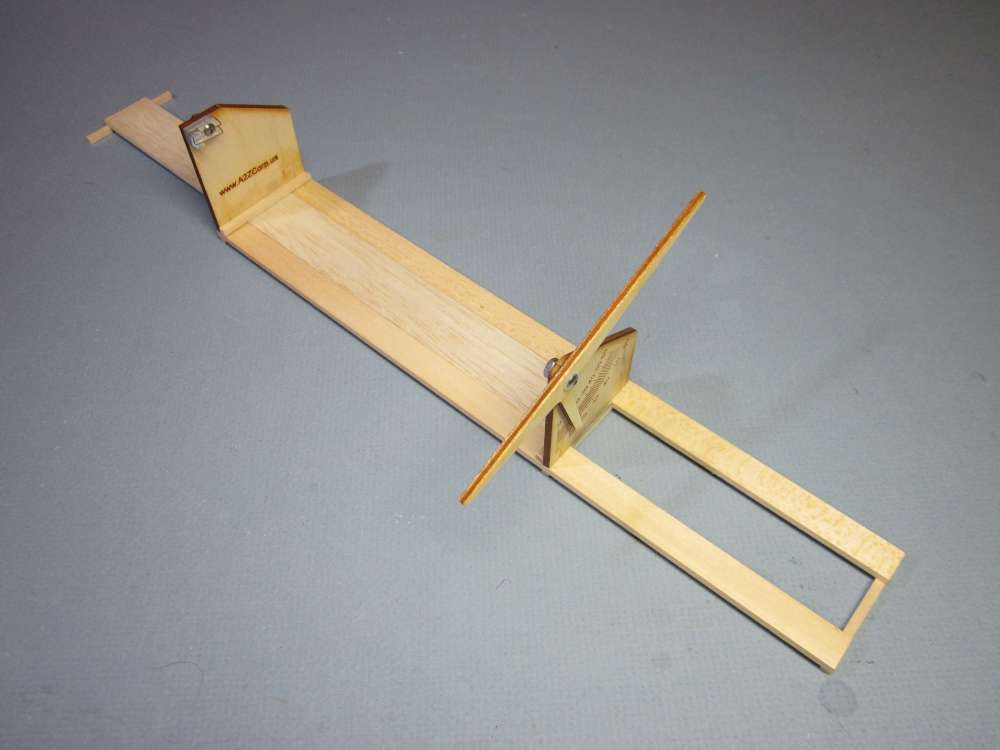
I made a slide rule base for it, which allows continuous adjustment of the distance between the V-block and the protractor. This was more a proof of concept than practical instrument. I don’t know how reliable it is, with the somewhat flexible base. I used 12″ model railroad basswood. This would allow measurements of up to 24″ diameter props. It would have made better sense to cut it to 6″ length.
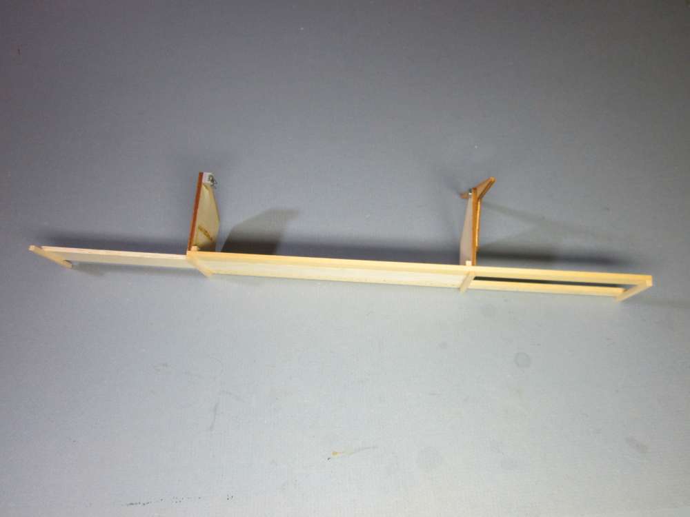
The slides are joined with six 1/8″ square ties, 2″ long, above and below. Center slide is 1″ wide, side slides are 1/2″ wide, all 1/8″ thick. Assembled with a temporary strip of graph paper between the slides, so it would slide easily when the paper strip was removed.
It couldn’t be used for plastic props, though, because even when the prop was pushed all the way down to the V-block, the blade was still 1/4″ above the indicator arm. Indoor prop hubs are horizontal tubes and the blade is glued to a round spar that fits into the tube. I could glue a 5/16″ strip onto the arm, or lower the V-block. Lowering the V-block would require removing the whole end plate from the base and cutting an exact strip off the bottom.
FURTHER IMPROVED A2Z PROP GAUGE
I tried various improvements to my A2Z prop gauge. The newest one is giving results mostly consistent with older methods, much quicker, but not as precise as I would like.
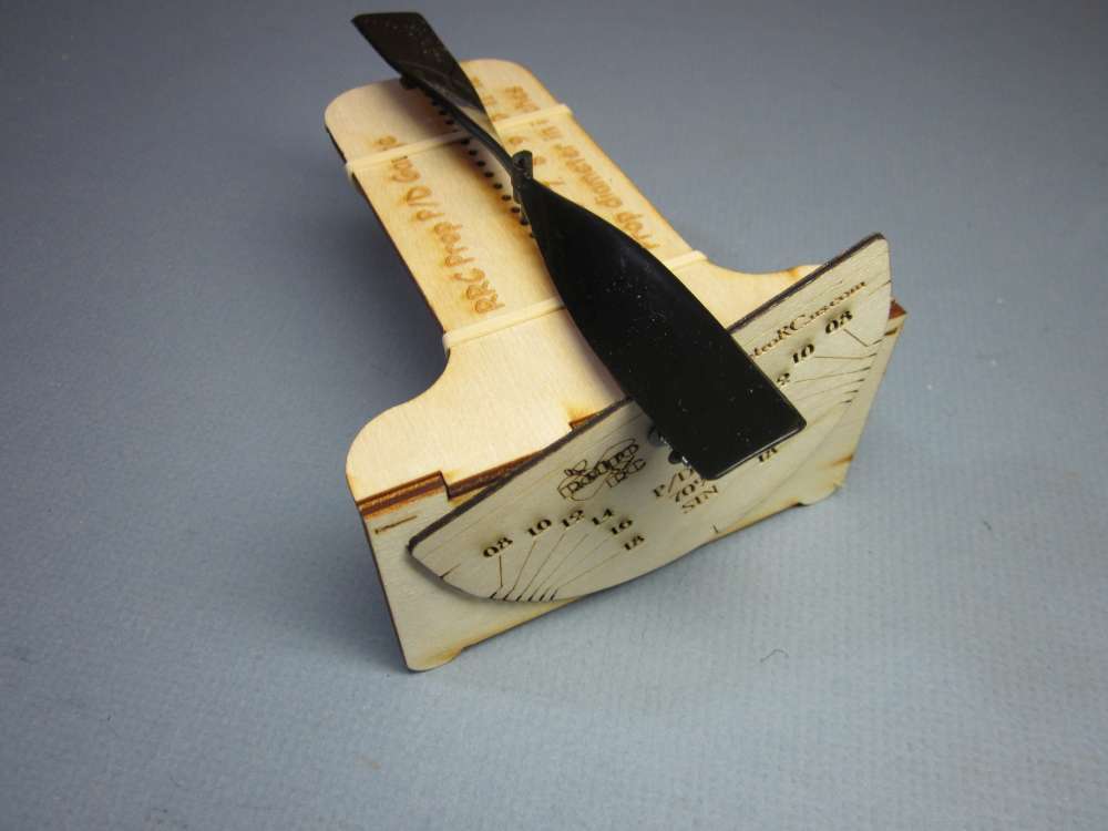
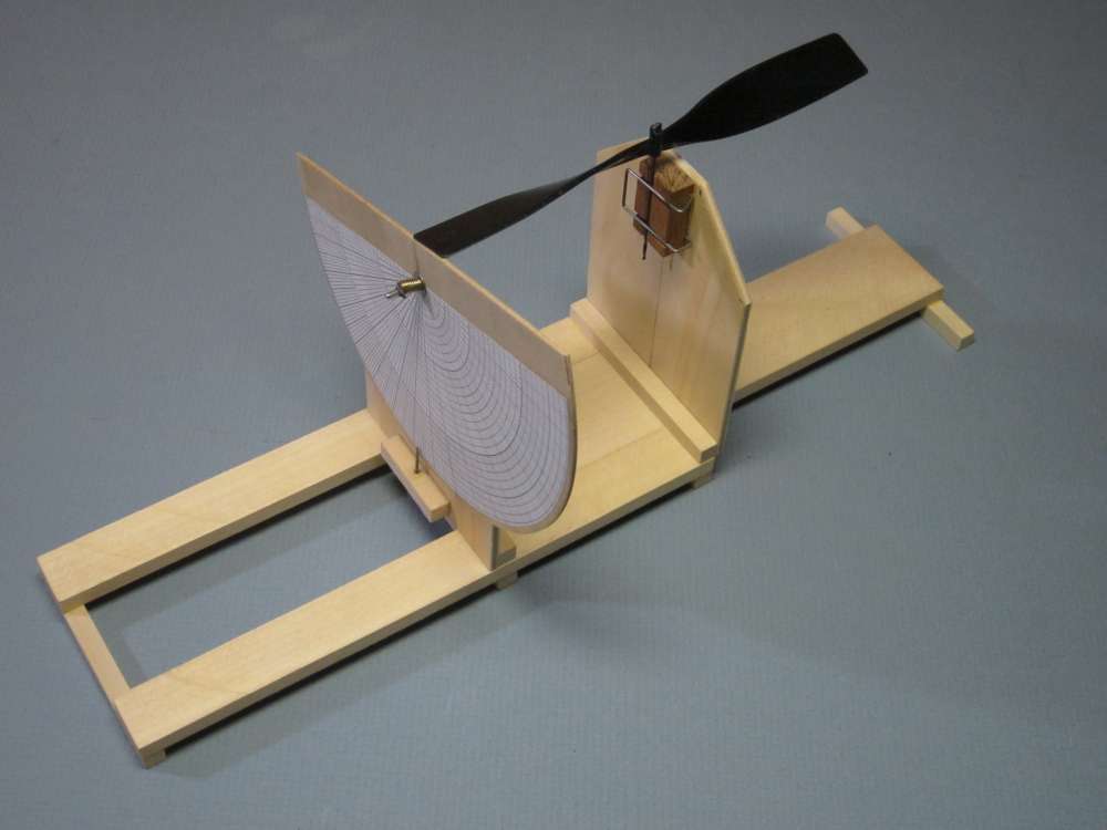
This is the A2Z gauge mounted on a 6″ slide rule base with an added 5/16″ bar to raise the protractor base line up to the lowest position of the prop chord.
Here is a graph of the measurements made by this gauge on the MPC 6″ black plastic prop.
This lists all the changes I have made to the small prototype slide rule gauge I made from parts of the A2Z gauge.
1. The prop could not be lowered enough to touch the protractor. I added a 5/16″ wide strip of 1/8″ basswood to raise the edge of the protractor.
2. The base was originally made from 12″ basswood strips. This felt a little flimsy. I cut the base down to 6″ length. (I now have base parts for another 6″ gauge.) The maximum extension measures the radius, so this will measure up to 12″ diameter props.
3. I removed the nut and bolt holding the protractor and replaced them with a sprung unit like the one on the RetroRC/Laser Cut Planes gauge (discussed later in this report). This allows the protractor to be moved easily and it stays in place when released. The shaft is a 1 1/4″ box nail with a 3/16″head, 0.0735″ shaft diameter and cut down to 3/4″ length. The holes were too loose for the nail, so I carefully round filed them concentrically to a 1/8″ diameter and inserted a 1/8″ brass tube that extends just shy of all the way through the two ply pieces and is a snug fit.
4. The 0.015″ wire prop shaft clip was too flimsy to hold the props securely in place. I replaced it with 0.025″, a bit stiff in this size, 0.020″ might have been better.
To properly calibrate the zero point, the indicator is clamped to the zero mark with a clothes pin, a hardwood “prop block” with perpendicular 1/16″ shaft is put in the clip and brought into contact with the indicator bar and the V-block was adjusted with pliers until the bottom of the prop block is flat on the indicator bar. The prop should be brought down until it just touches the indicator bar. The indicator bar should not be allowed to apply any force to the prop. If it does, the bottom of the shaft may be loosened from the V-block and the prop can tilt out of true.
I tested this on the 6″ black MPC prop and the results were consistent with other methods I have used. This is now a worthwhile addition to my prop tool kit. I will be able to use it in classes to teach about propeller geometry.
RETRO RC/LASER CUT PLANES PITCH GAUGE
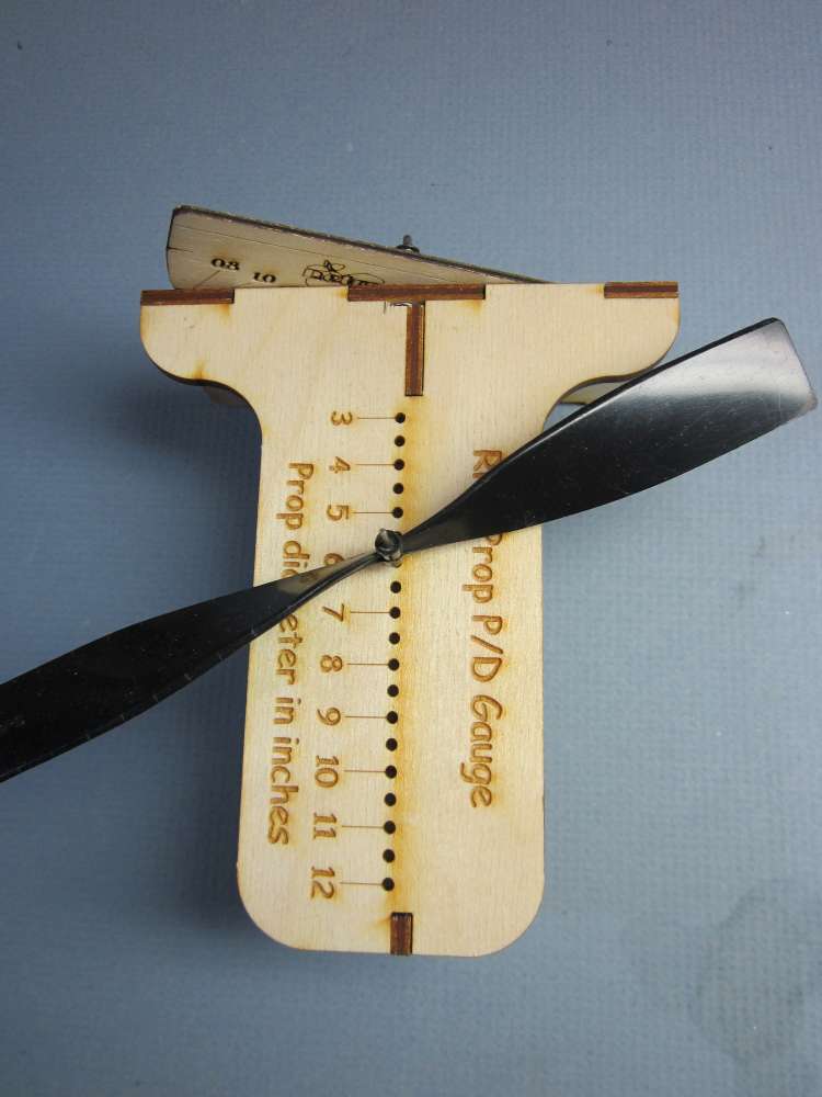
Retro RC/Laser Cut Planes offers a kit for a prop gauge. I studied it carefully and downloaded the pictures. Verified that the P/D marks were at the correct angles. It does not have blade angles, but I could glue a paper protractor on the front, or turn it over and glue the paper protractor to the back. It does not have continuous radius positions but the 0.175″ spacing between fixed positions is not too bad. The minimum is 37% of a 6″ prop. I would have to drill more holes to get down to 10%. I decided to buy one.
I was pleased when a few days later a small box arrived. It seemed too small, until I considered that it measures along the radius, only half the diameter. I set to work building it. I put it together dry, without glue, because I might want to rebuild it. I encountered several problems that I was able to overcome.
1. There was an incomplete burn thru on part A, left rear, that resulted in a splintered edge of the wood. If I had seen this sooner, I could have cut it free with a blade. You have been warned!
2. Everything was a snug slip together except part B into part D. Light sanding revealed a slight warp of B.
3. The protractor shaft 1/16″ steel wire is hard to cut, harder to bend. Bent in a vise with a block of wood. The bend is radiused. The wire would not fit in the space between A and C. A would not go down all the way. I filed a curve on the corner of C so the wire would fit. I am thinking a small box nail with a 1/16″ shaft could be used here.
4. The spring was so long that even when fully compressed, there was not enough room for the retainer to go on the endof the 1/16″ wire shaft. I cut the spring in half. Maybe I could have made the wire shaft longer, but too late now.
5. The retainer would not go onto the 1/16″ rod. I filed a taper in the remaining piece of 1/16″ and hammered it through on the vise. After that, it went on. If I had tapered the end of the shaft rod, it might have gone on.
6. The spring pulls the bent wire shaft forward, out of alignment with the holes in C and D, not parallel with A. I pushed in on the spring to get the parts together.
7. When the 0 marks on the left are aligned, the 0 marks on the right are not. Pushing down on the protractor aligned them, but there is play in the bearing. The discrepancy will not affect the readings, which are in P/D values of 0.8, 1.0, 1.2, 1.4, 1.6 and 1.8.
8. The 1/16″ steel prop support rod is loose in the holes in A and E, so not perfectly perpendicular to the reference plane. Could be fixed with tissue wrap.
9. The 1/16″ steel rod does not fit inside the hub of even the biggest prop I have. The holes are all different. See my report on Plastic Propellers. It will require a variety of wire rods wrapped with tissue to fit, as with any other prop gauge.
10. The 1″ of brass tube was not present. Not missed, I have plenty around the shop. And it may not be needed anyway.
11. The 1/16″ rod slides down through the holes in A and E. Dental elastics could be wrapped around it, or O-rings put around it, or thin plastic disks pushed over it. A length of ball point pen tube could also be used beneath the prop to support it. Lengths 1/32″, 1/16″, 1/8″ and 1/4″ would cover the required range in 1/32″ steps. Tissue wraps would make up the differences.
I held it together with rubber bands for a test.
A 6″ black Midwest prop is a tight fit on a 0.0462″ drill rod. A couple wraps of paper make it a snug fit in the plywood holes. The blade rotates into contact with the protractor. The scale indicated P/D of exactly 1.0 at the 70% radius. About what I would expect, consistent with what the other gauges indicate. Several repeats got exactly the same result. Looks good. This is good if you want a P/D at a fixed radius. The P/D values are limited to 0.8, 1.0, 1.2, 1.4, 1.6 and 1.8. It would be good to add 2.0 and 2.2 for duration props, easy enough to do. Those will be at 42.3 and 45.0 degrees. It could be modified to measure blade angles by gluing a paper protractor on the back and reversing the dial. Either of these changes is best done before assembly. It is difficult to find push nuts locally.
I like the spring friction fit of the protractor. The A2Z protractor is tightened with a nut. You are supposed to put CA on the nut to keep the adjustment. But as it wears, it gets loose again. The spring is self tightening. I like the V-block shaft holder of the A2Z unit. I like the slide rule base. I am thinking to build one that combines those features with a bigger protractor for greater precision.
I made the suggested changes to the gauge.
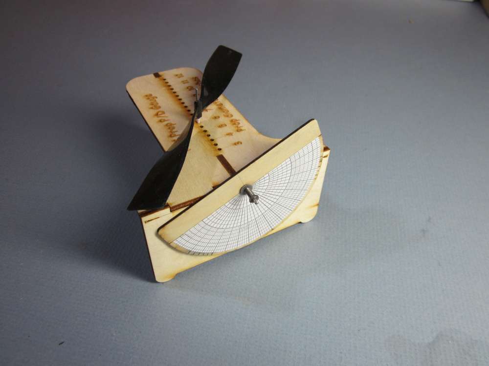
I removed the bent 1/16″ wire shaft and replaced it with a nail. I turned the P/D scale around and glued a paper protractor to the back.
I removed the bent 1/16″ wire protractor shaft and replaced it with a small box nail, seen here, cut to 5/8″ long, as was done with the A2Z gauge, above. This required filing a bit away from parts A and B to clear the nail head.
You can see better where a bit was also filed away from the top corner of part B to clear the nail head. Part C is no longer necessary. This makes it possible to drill additional 1/16″ holes in A and E for closer positioning of the prop shaft to the protractor.
The spring that was an easy fit on the 1/16″ shaft was too small to go on the 0.0735″ diameter nail. I drilled a 0.0275″ hole in the end of a nail, put the end of several inches of 0.016″ steel wire through the hole and bent it over. I turned the nail by hand with a pin vise and evenly wrapped the wire on the nail. This made a nice spring about 0.118″ diameter. I stretched it out to open the coils and cut it to 10 loops length. This went together nicely and keeps a good friction contact between the protractor and the face of the gauge body.
The prop was a snug sliding fit on a 0.045″ steel wire shaft. That wire would be a wobbly fit in the 1/16″ = 0.0625″ holes in the gauge base. The diameter must be increased by 0.0175″ by wrapping and gluing paper around the shaft. Paper folded twice to make four layers measured 0.0111″ on the micrometer, or 0.002775″ each. We need 6 layers of paper, or 3 wraps, to bring it up to size. Assuming each wrap to correspond with the circumference of the wire, we need a π x 1/16″ x 3 = 0.6191″ ~5/8″ long strip of paper. The width of the paper strip is a bit more than what is needed to span the distance of parts A and E, about 7/8″, I used 1″. We glue the shaft along one 1″ edge and let the glue dry. Then we paint the inside surface of the paper with slightly diluted glue and wrap the paper around the shaft. Finish by rolling the wrapped shaft under a block of wood and over a smooth, hard surface, rolling in a direction that will roll the paper strip tightly onto the shaft. Let the glue dry thoroughly before attempting to put it into the gauge.
A similar technique is used to upsize a wire shaft to be a snug fit in a prop hub.
THE ULTIMATE PROP GAUGE
I wanted greater precision in the angle readings. Doing that requires a larger protractor with larger divisions between the degree markings. I also wanted a spring retained protractor and a slide rule base, combining the best features of the previous prop gauges. A longer V-groove to hold the prop shaft would be more stable.
The new one is 8 1/4″ long, 3″ wide and 4 5/8″ high, except for the protractor, which is 6″ diameter. It is capable of measuring up to a 14 3/4″ diameter. I will describe it in detail in case you are interested in making one.
This is similar to the other one, except bigger. The main other differences are the full 180 degree protractor, which can measure left hand props as well as right hand props, a hardwood (mahogany) prop shaft holder V-block and an indicator pin.
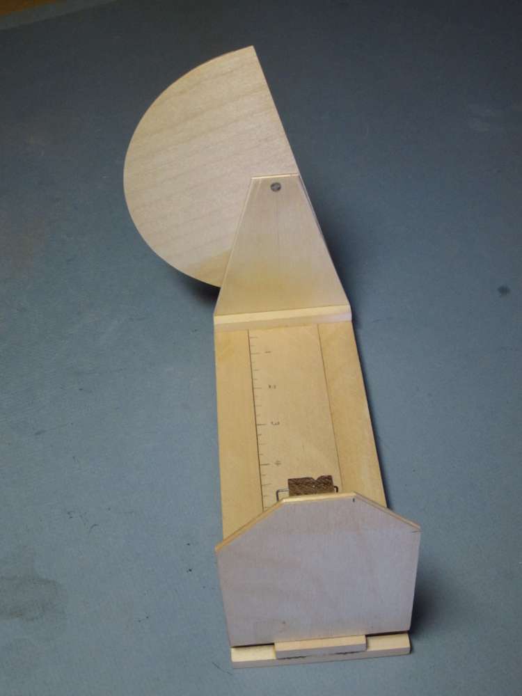
Originally both upright plates were the same. I found that at high blade angles, close to the prop hub, the corner of the plate projected beyond the edge of the protractor, making it difficult to align the blade chord with the edge of the protractor. I recut the protractor support upright to give better clearance, as shown here.
Bill of materials:
Quantity; Name; Dimensions; Material
2; side rails; 1/4″ x 3/4″ x 8″; basswood.
1; center rail; 1/4″ x 1 1/2″ x 8″; basswood.
6; cross ties; 1/4″ x 1/4″ x 3″; basswood.
2; upright plates; 1/8″ x 3″ x 4″; birch ply.
1; protractor base; 1/16″ x 3 1/2″ x 6″; birch ply.
1; protractor; 2 5/8″ radius semicircle; copy paper (including the numbers, cut out and glued on).
1; box nail; 1 1/4″ long, 0.0735″ shaft diameter, 3/16″ head diameter; iron.
1; push nut, 1/16″; steel, Zoro Product Number G0366326.
1; spring; half of the spring from a ballpoint pen, 1/8″ diameter, about 10 loops of 0.015″ diameter; steel wire. Larger diameter wire might be better.
1; washer; 1/4″ od, drilled id to 0.089″; steel.
1; V-block; 3/8″ x 5/8″ x 1″; mahogany.
1; clip spring; 1/4″ x 1/2″ x 7/8″ bent up from 4 1/2″ of 1/32″ diameter; steel wire.
1; pointer; 3/4″ length of 1/32″ diameter; steel wire.
1; pointer block; 1/4″ x 1/4″ x 1/2″ ; basswood.
various; prop shafts; 2-3″ lengths of various diameter; steel wire.
various; strips of tissue paper as needed to enlarge wire to snug fit in prop hub.
Titebond or similar wood glue.
Sig nitrate dope.
The slide rule base is made first. Pieces must be glued together square and without sticking to the adjacent assembly, while being a close fit. This involves applying glue with a small flat brush while the parts are held snugly together, but keeping glue back from the adjacent sliding part. Parts are clamped between plywood plates in a vise while glue is drying.
The outer third of the top corners are cut off the upright plates at 45 degree angles to allow easier access and to prevent the prop blade hitting them. This could have been a steeper angle, 60 degrees. Centerlines are drawn on each, using a drafting square against a straight block of wood to get them perpendicular with the base. A 0.073″ hole was drilled 7/32″ down from the top of the protractor upright. There were ridges on the nail shaft that had to be filed off. This resulted in a snug fit.
The paper protractor was cut around the perimeter of a tea saucer. The ply protractor is 3″ radius with a 1/2″ strip across the flat side. It was given a coat of Sig nitrate dope, allowed to dry, second coat applied, when tacky, the paper protractor was put down, very carefully aligned and pressed down with a block of wood. The straight edge of the protractor was placed 1/2″ from the edge of the ply and exactly centered. Then the 0.073″ hole was drilled with a drill press. The drill was aligned by putting a sharp pin into the drill chuck and bringing it down to poke into the intersection of the two lines, the ply was taped to the drill table, chuck raised and pin replaced with drill.
The wire clip should be made from the center out. Otherwise it is nearly impossible to get it symmetrical. Start with a 4 1/2″ piece of 1/32″ wire, ends filed dull. When wire is bent in the pliers, the bent piece will end up about one wire diameter out from the face of the pliers. Keep that in mind when making each bend. We want a square U with 1/2″ between the legs. So we put the face of the pliers 1/4″ – 1/32″ = 7/32″ out from the center of the 4 1/2″ piece of wire. Bend both legs and adjust to get both bends perpendicular and all three lengths of wire in the same plane. The next bend must be exactly the same distance down each leg from these bends. To do that, put the U in the vise, 7/8-1/32″ down with the two legs sticking up. Get them perpendicular to the top of the vise. Tighten the vise. Now bend both at the same time, using the end grain of a block of wood to bend them over. Adjust to get them perpendicular and parallel with each other. Next bends are made 1/4-1/32″ from these. This has to be done with the pliers, but in the same way; gripping the wire tightly with the edge of the pliers perpendicular to the wire, bend both at the same time. Be careful, the one farthest away from the joint in the pliers is not as tightly held. Adjust so the ends are perpendicular to the 1/4″ sides, parallel to each other and to the other 7/8″ sides.
The 3/8″ x 5/8″ x 1″ V-blocks were cut from scrap mahogany. I made about a dozen of them. A V notch was cut down the center of one of the long faces. This was cut with the saw table set at 45 degrees. The kerf was about 1/16″ deep. Two crosscuts were made at right angles to this, with the table level, just a hair deeper than the V. The centers of these crosscuts were 1/4″ in from the ends. Directly opposite these, on the back face, shallow grooves were filed with the triangular machinists file, just deep enough to hold the 1/32″ wire clip securely. The wire clip slides into these grooves and kerfs. Several pieces of wire in different diameters are used to support the props, supplemented as necessary with wraps of tissue to be a snug fit in the prop hub. To glue the V-block on, a ~6″ length of perfectly straight wire (test by rolling on a flat surface) is clipped into the V notch. Glue is applied to the back of the block, the block is put in place, wire aligned with the perpendicular pencil line, and verified with a drafting triangle, the base and triangle on a flat surface. When set, the assembly can be clamped until the glue dries.
The protractor upright is assembled by pushing the nail through the upright from the back, putting on the protractor, the washer, the spring and the push nut. The nail was cut to a 9/16″ length. The end filed flat, then tapered to a circle on the end equal to the hole in the push nut. Getting the push nut on can be trying. You may be required to chase after that spring several times before success. A hole is drilled in a block of wood a bit smaller than the push nut. The push nut is placed with the conical side down in the hole. The nail and spring assembly is held together with a thin stick (half a clothespin or a Popsicle stick) with a groove filed in it that will straddle the nail and keep the spring on. Place the point of the nail at the hole in the push nut and give the head of the nail a light tap with a hammer. I think a slightly stiffer spring might be better.
Glue the uprights to the outsides of the upper cross ties, as shown in the photo. The V-block faces in, the protractor faces out. Be careful to not glue moving pieces together. Get the centerlines perpendicular with the base using a drafting triangle. Clamp in place with clothespins, let the glue dry.
The alignments of the protractor and uprights does not need to be absolutely perfect, just eyeball close. The final placement of the pointer will compensate for any minor misalignments of the protractor or uprights.
Apply the pointer. Drill a 1/32″ hole square into the holder block about 3/32″ in from one face and halfway along the length. File a point in the needle. Put it in the drill chuck and finish it with a sharpening stone, first coarse, then fine. Dip the blunt end in glue and insert into the hole in the block. The protractor must be set at zero. This is done by making a “propeller” blank from hard wood, with a 1/16″ hole drilled absolutely perpendicularly through it. This should be at least an inch wide. It occurred to me later that it would have been preferable to use a plywood plate at least 3″ wide. Put a 1/16″ shaft into the hole and clip the shaft in the V block. Slide the block down until it rests on the protractor and the protractor edge is in uniform contact with the under surface of the block. Clamp the protractor in place with clothespins. Recheck alignment. Now put glue on the inside face of the pointer block, align the pointer with the zero line on the protractor and press the block into place. Check as the glue dries that it has not drifted.
Put the radius marks on the base. Slide the uprights apart until there is exactly 3″ between the shaft and the back face of the protractor. Put a pencil mark down across the separation between two of the base strips along one inside cross tie. Now push the ends back outward to full extension. Write 3″ at the mark. With a small ruler, put marks every 1/4″, or whatever divisions you require, and label them accordingly.
That completes construction of the gauge. Next step is to test its reliability. I measured blade angles at 1/4″ stations on the 6″ black plastic MPC prop. I did it five times and calculated the mean and standard deviation at each radius. The standard deviations averaged 0.46 degree. Not the 0.1 degree precision I had hoped for.
I think it is capable of better reliability than that. As I worked with it, I noticed certain things. The thin plastic prop blades are somewhat flexible, requiring a delicate touch. Thicker blades may be less flexible. A wider chord gives a more reliable base for establishing a chord line. The prop must be slid up and down to bring it into alignment with the protractor edge. The prop radius should also be perpendicular with the upright face. I start at the tip with the protractor at an estimated angle and bring the prop down to it, adjusting the protractor as it gets closer until they are close, but not in contact, and the leading edge is slightly high. Bring the trailing edge into contact with the protractor, then apply very light pressure at the hub to keep the prop in very light contact with the protractor while rotating the protractor until it just contacts the leading edge. Do it again, but this time, start contact at the leading edge. You should get the same result. At each succeeding radius, the angle would be higher. With very light pressure near the hub, I would rotate the prop trailing edge into contact with the protractor, then slowly rotate the protractor up until the leading edge just touched the protractor. I found the spring was not always strong enough to hold the protractor in place, so I clamp it between my thumb and fingers to read the dial.
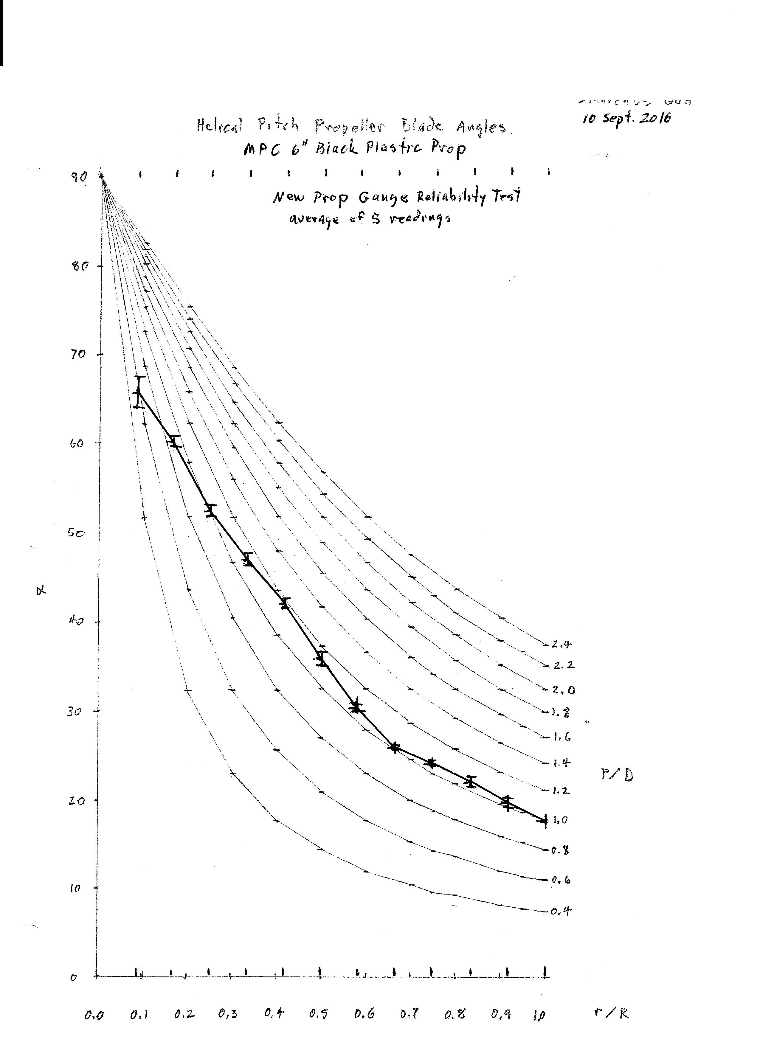
This graph represents the average of five sets of measurements. Except at the 1/4″ radius, where it is difficult to establish a chord line, the standard deviation of the measurements averaged 0.46 degree, as indicated by the error bars on the graph. It takes about ten minutes to take a set of measurements with this gauge, compared with the hour or so it took with the block and protractor method or two hours with the chord and offset method.
Thanks a lot🙏
I have learned a lot from you on this site.
Hello,
What will happen for attack angle if the pitch angle be quite helical?
Alpha will be constant at any radius of blade?
Or it happen just for special speed and rpm?
I checked those formula on a Excel work sheet for different speed and rpm but the Alpha graph was like your graph here at any test.
Good question. Let’s look at the first graph, above. Assume the advance angles are per flight test, with helical J = 0.7149, and the blade angles correspond to constant helical P/D = 1.0. The attack angles will be the difference between the blade angle and the advance angle. Both curves are shown, you can scale off the attack angles. You can see that the attack angles are not constant. Attack angle will be optimal at only one radius. However, the attack angles will be close to optimal over most of the outer portion of the blade. A helical prop may not be perfectly optimal, but it is pretty good, and it is easier to lay out for carving.
OK thank you.
In the third edition of Martin Simons’s book, Model Aircraft Aerodynamics, page 212, he mentioned for a helical prop, each part of the blade will be at the most efficient angle of attack for an air speed and a rotation rate.
So that’s not entirely true.
Can we reduce pitch angle near the hub for better result and using the whole blade?
How much the difference will be?
Or it is better to just focus on outer part of blade?
Simon’s statement is not at all true, as we see from the above example. The advance ratio must be helical, by definition. The attack angle is the difference between the advance angle and the blade angle. You can get an idea what an attack angle curve would look like for a helical prop by comparing two helical curves. You can see that the angles differ by some amount at the tip, that the difference increases as you move inward, to a point, then the difference decreases to zero as all helical curves converge to 90 degrees at the hub.
Assume we know the optimum attack angle for the blade airfoil. Assume we know the advance ratio at which the prop will operate. We can then calculate the optimum blade angle at each radius by adding the optimum attack angle to the local advance angle at each radius. This would allow us to lay out a block for carving the optimum prop. Unfortunately there is very little aerodynamic data for the airfoils used on our props. The best we can do is look for something that is somewhat similar. Unfortunately the available data is not for Reynolds numbers in the range where we operate. The best we can do is test a series of props and select the best one.
All our theories of propeller operation are based on simplifications which give some degree of approximation. We assume the air moves straight through the propeller disk. This is not exactly true, because as the cylinder of air affected by the propeller moves through the propeller disk the air is accelerated. Thus the cylinder must contract as it moves through the disk. So there is a slight inward motion of the air. The propeller blade functions as a three dimensional wing, with outflow along the underside and inflow over the top, with the resulting vortex wake off the tip. This also affects the angle at which the air approaches the blade. Also, the blade airfoil is not constant along the radius, the chord and thickness vary, so we cannot assume a constant optimum attack angle. At the low aerodynamic scale at which our propellers operate, changes in scale can have a large effect on the lift and drag coefficients of the airfoils. The chord varies along the radius and the relative air velocity increases greatly as we move out to the tip.
The usefulness of the precision with which we analyse propellers is limited by the precision with which we can make propellers. A pencil line on the side of the block corresponds to about one degree of blade angle. The blade angle carved depends on two pencil lines, one on each side of the block. Even if you check your carving with an accurate prop gauge, your precision is about half a degree. Theories that cut finer than that are thus of limited practical value.
great engr.very help full prop gauge