A propellers performance depends on the distribution of blade angles along its radius. The blade angles must correspond to the advance ratio, the ratio of forward speed to rotational speed, plus an attack angle. For a fast climb, a low pitch is preferred. For slow climb, cruise and descent, a higher pitch is preferred. For moderate performance in all phases of flight, a mixed pitch might be preferred. I have measured the blade angles of several propellers. These reports may be useful in judging the performance of various props.
I will list them in order of increasing diameter.
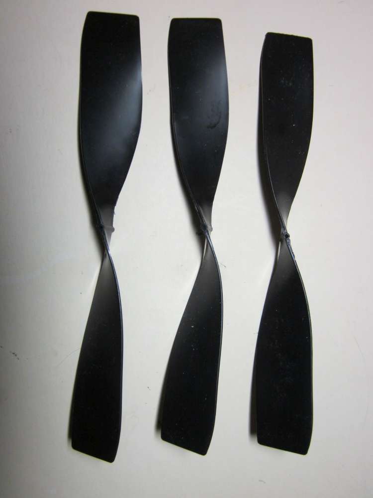
6″ Orange Chinese Prop
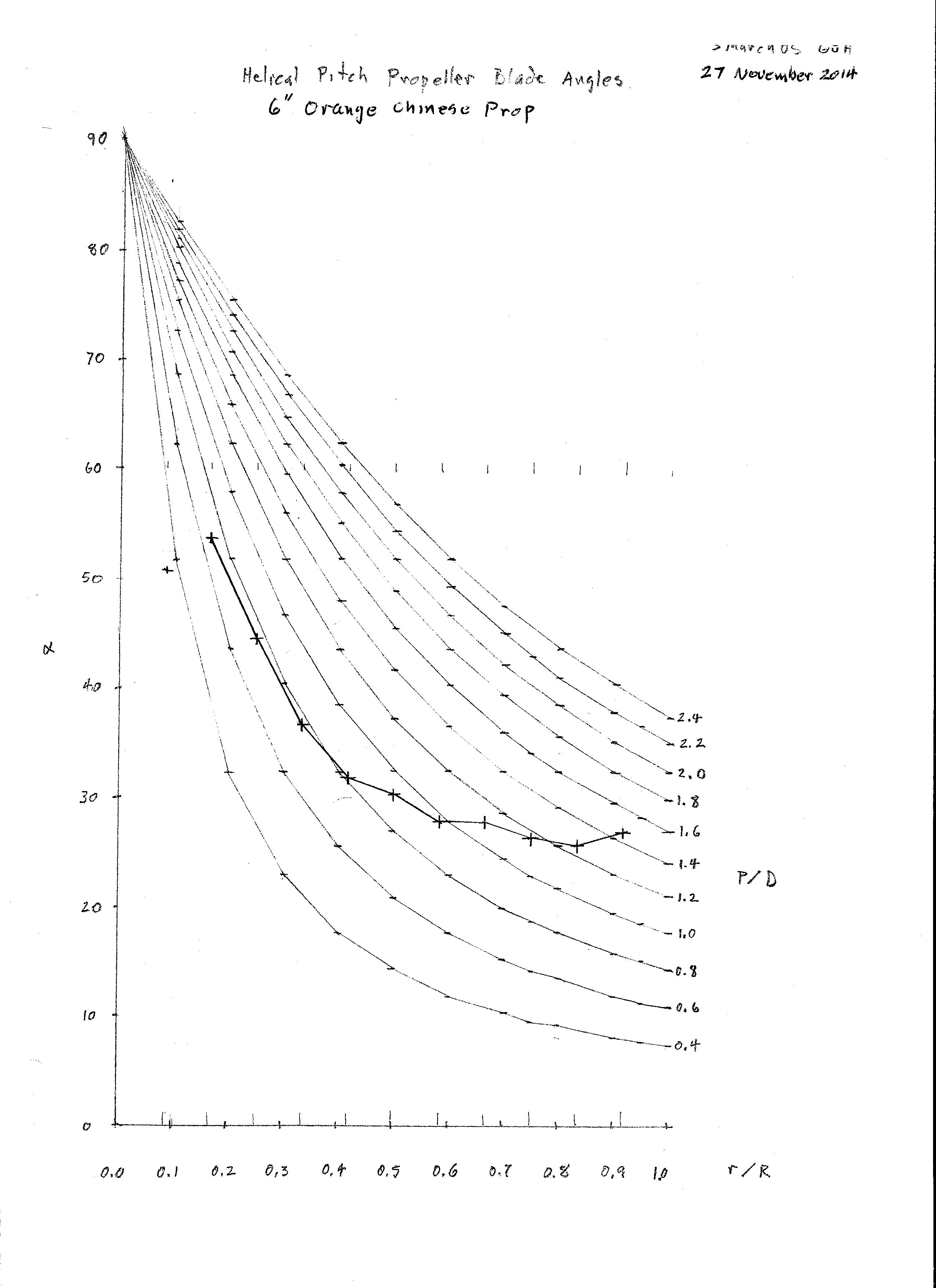
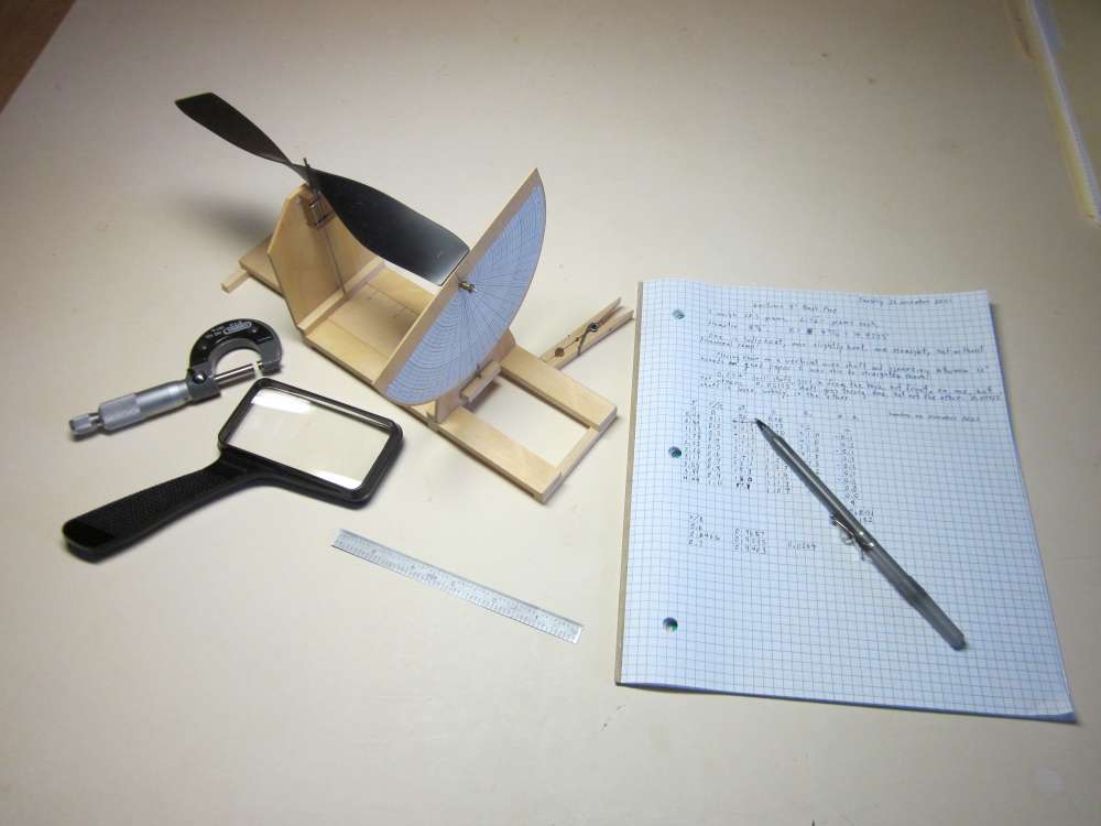
Here is my plot of the blade angle versus radius fraction, r/R. Measurements were made at 1/4″ stations along the radius. The prop was rigidly mounted on a vertical shaft. Chord (c), leading edge (LE) offset above table and trailing edge (TE) offset above table were measured to the nearest 0.01″ at each station. Blade angle (B for Beta) was calculated trigonometrically. P/D was calculated from the usual formula.
B = arcsin((LE-TE)/c)
P/D = pi tan(B)r/R
Wobbles in the graph result from measurement precision limitations rather than manufacturing irregularities. The 0.01″ precision corresponds to about 1 degree.
The blade angle plots in the background are for helical props with the P/D as shown along the right edge. You can see by comparison with the helical plots that this is not a helical prop. The P/D ranges from 0.7 to 1.4. The washin at the tip is due to the sharply swept tip rather than twist of the basic shape.
I calculated the representative radius at 1.73″, 0.577 radius. The corresponding P/D is 0.957. The P/D varies so much that it would not be especially efficient at any particular advance ratio, but it might be somewhat effective over a wider advance ratio range than a prop with a higher maximum efficiency.
Representative radius is calculated by multiplying each chord by the square of the radius, summing the results, dividing by the sum of the chords and taking the square root. It is different for each blade shape. This is a rule of thumb number, like the P/D, and should not be taken with too much seriousness.
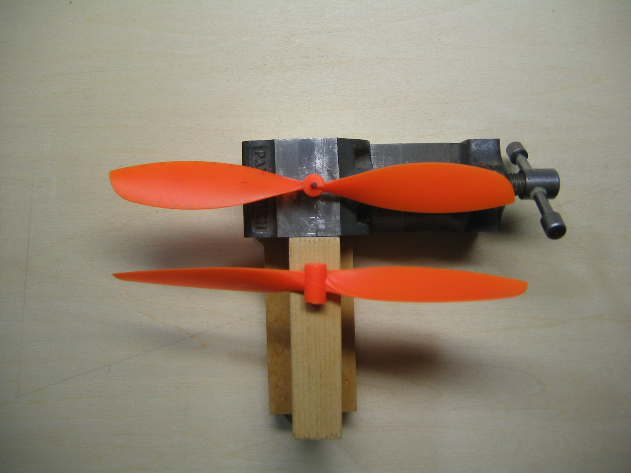
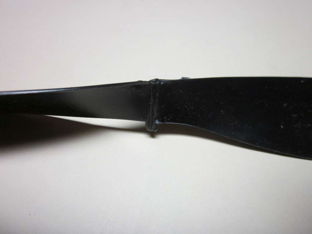
Two props weigh 5.6 grams, 2.8 grams each. The cylindrical hub is 0.31″ in diameter and about 0.59″ long. The hole is different diameter on front and back. The front hole is larger to clear the bend in the wire shaft. The back hole was a sliding fit on a 0.0593 drill shaft and 0.34″ deep. The front hole was snug on a 0.0985″ drill shaft and about 0.18″ deep. The ramp is about 0.10″ high. For measuring, I put a 0.05″ wide strip of 0.0041″ thick paper through the hole to get a snug fit.
9″ Black Guillows Prop
Guillows lists a a 9″ black plastic prop among their kit replacement parts. They are not listed on their bagged parts page. Replacement parts are sold individually and the price is quite a bit higher per item than the equivalent bagged version.
If you contact Customer Service you may be able to buy several of them at a lower unit price. Guillows has a $10 minimum order, so look around and see what else you might like to get at the same time.
It occurred to me that this prop might work for P-30 class models, although the rule allows 9.5″ diameter props and the larger diameter is an advantage.
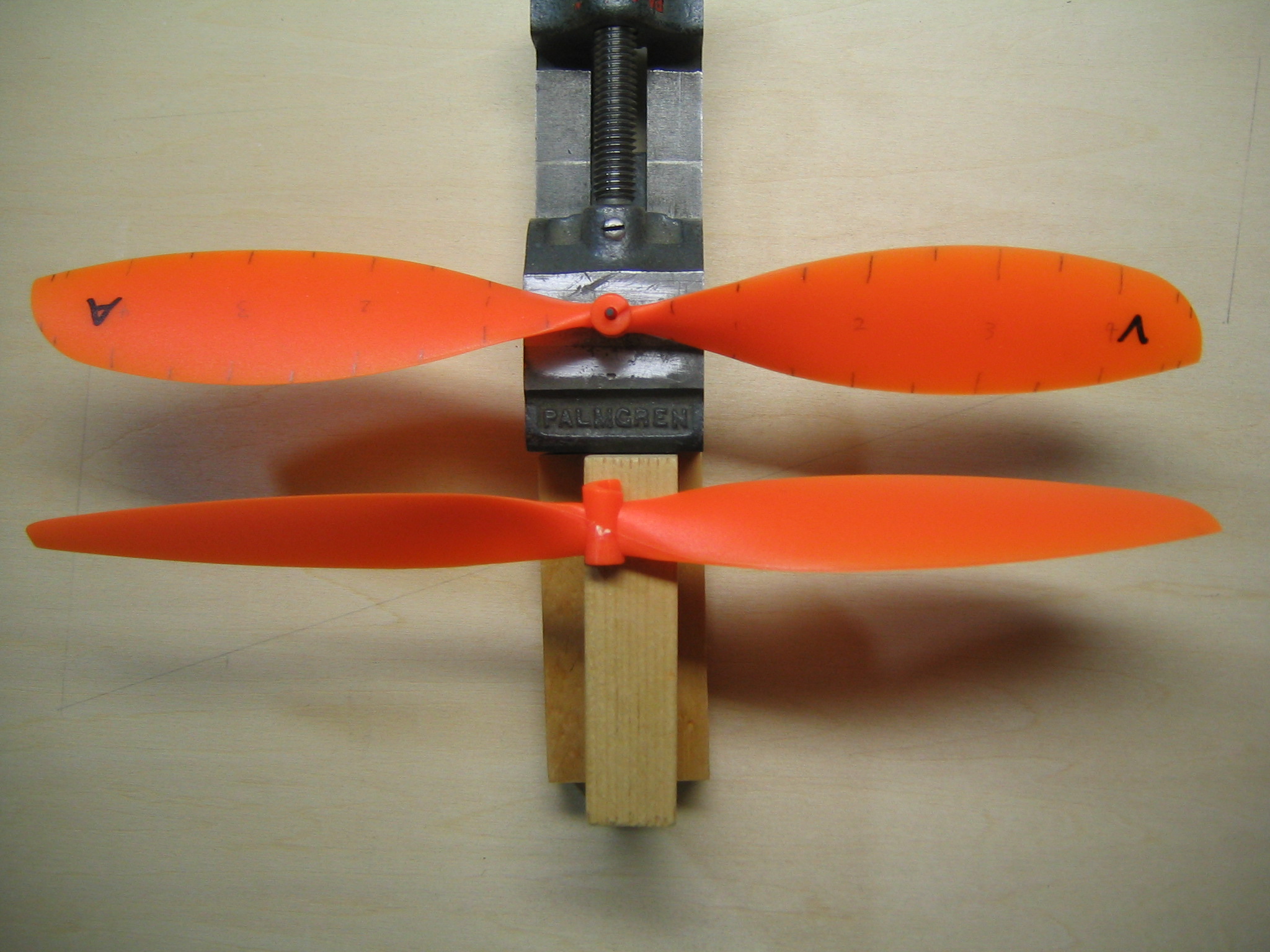
I ordered three props. I was a little disappointed that one of them was bent and one lacked the freewheel ramp.
It was easy enough to unbend the bent prop and I can make a free wheeler for the other, but still, quality control is important. This may have something to do with the pandemic, access to inventory and supply chain issues.
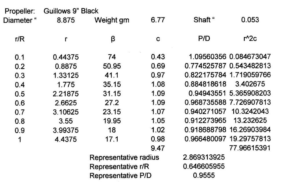
The main reason I bought this prop was that I didn’t have a specimen and I wanted to include it in my study of plastic props. It is actually 8 7/8″ in diameter. This prop is light for its size, 6.77 grams. The blades are very thin all the way to the hub. That might make them bend on striking the ground at landing. The hub is also small, as you can see in the photos. It resembles the North Pacific props. However there is little to no camber. I numbered the blades 1 and 2 and measured the blade angle and chord at 0.1 radius fractions. The blade angles at corresponding radius fractions of each blade were within about 0.15 degree of each other, within the precision of the measurement.
The table shows the radius fraction, the radius, the blade angle, the blade chord, the local P/D and the square of the radius times the chord. The last is used to calculate the representative radius and fraction, as seen below. The representative P/D is interpolated from the values in the table.
Note that the P/D is not constant, although much more consistent than most other plastic props.
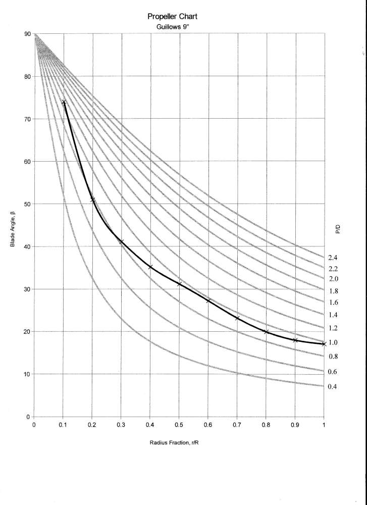
The plot shows that this prop tracks the local helical curves pretty well. The maximum L/D of these little airfoils occurs somewhere around 4 to 6 degrees. It would function efficiently at an advance ratio somewhere around 0.7 – 0.8. This might be a good prop for rapid acceleration, high speed or a rapid climb. It would not be so good for a long cruise. How it would perform in combination with an aircraft and motor must be found out by test.
9 1/2″ Orange Chinese Prop

There is an article in Free Flight Quarterly, Issue No. 53, October 2014, pages 31-32,”A New Propeller for P30″ by Paul Rossiter, about the new Orange Prop. It is a continuation of the article in Issue No. 15, “P30 Propeller Analysis” that evaluated IGRA, Peck, Gizmo Geezer and Modella props. It concludes “The Orange propeller is an excellent replacement for the Peck prop and one of the best (if not the best) available for P30”.
Here is my plot of the blade angle versus radius fraction. Measurements were made at 1/2″ stations along the radius. This is the average of six measurements, three on each blade. Standard error is about 0.81 degree. High and low measures are plotted. The measurements of each blade were within tolerance of each other. The tips track well.
You can see by comparison with the helical plots that this is not a helical prop. The P/D varies tremendously. The tip washin is due to the swept leading edge.
This plot matches that in FFQ except at the mid radius, where I think there is an error in the FFQ measurement.
I calculated the representative radius at 2.93″, 0.614 radius. The corresponding P/D is 1.03. It is misleading to quote a P/D for a non helical prop.
Representative radius is calculated by multiplying each chord by the square of the radius, summing the results, dividing by the sum of the chords and taking the square root. It is different for each blade shape. This is a rule of thumb number, like the P/D, and should not be taken with too much seriousness.
Two props weigh 14.45 grams, 7.225 grams each. The hole is different diameter on front and back. The front hole is larger to clear the bend in the wire shaft. There was flash about halfway through. The back hole was slightly loose on a 0.0593 drill shaft and 0.38″ deep. The front hole was slightly loose on a 0.0972″ drill shaft and 0.27″ deep. For measuring, I put a 0.05″ wide strip of 0.0041″ thick paper through the hole to get a snug fit. The tips tracked within 0.01″ of each other.
The FFQ article compares the props in a computational model. Such models make simplifying assumptions. There is no sensitivity analysis of how the outcome could vary with discrepancies in the inputs. It calculates prop efficiency at each revolution, total height and flight duration. A calculation is made for motors of 4, 5 and 6 strands of 1/8″. It finds maximum height of 82 m with 5 or 6 strands of 1/8″. It finds duration of 219 seconds with 4 strands, compared with 225 for the Peck. All of the props show maximum duration with 4 strands, which suggests the optimum motor is of smaller cross section. Each prop is likely to have a different optimum motor cross section with different durations. The Peck prop is closer to helical and may maintain its edge with a smaller cross section.
12″ Orange Chinese Prop
These differ from others in this series in that the plastic surface is glossy rather than frosted. Here is my plot of the blade angle versus radius fraction. Measurements were made at 1/2″ stations along the radius. The prop was rigidly mounted on a vertical shaft. Chord (c), leading edge (LE) offset above table and trailing edge (TE) offset above table were measured to the nearest 0.01″ at each station. Blade angle (B for Beta) was calculated trigonometrically. P/D was calculated from the usual formula.
B = arcsin((LE-TE)/c)
P/D = pi tan(B)r/R
Wobbles in the graph result from measurement precision limitations rather than manufacturing irregularities.
The blade angle plots in the background are for helical props with the P/D as shown along the right edge. You can see by comparison with the helical plots that this is much closer to a helical prop than most plastic props. Although it varies slightly, P/D is very consistent over the working part of the radius. The sharp washin at the tip is due to the sharply swept tip rather than twist of the basic shape.
I calculated the representative radius at 3.65″, 0.608 radius. The corresponding P/D is 0.727. This is a low pitch prop suitable for fast climbs, but not so good for long, slow flights under power. I expect it will operate best with advance ratios around 0.4 to 0.55, assuming a most efficient blade attack angle of 4 to 6 degrees.
Representative radius is calculated by multiplying each chord by the square of the radius, summing the results, dividing by the sum of the chords and taking the square root. It is different for each blade shape. This is a rule of thumb number, like the P/D, and should not be taken with too much seriousness.
Two props weigh 24.4 grams, 12.2 grams each. The cylindrical hub is 0.35″ in diameter and about 0.75″ long. The hole is different diameter on front and back. The front hole is larger to clear the bend in the wire shaft. The back hole was slightly loose on a 0.0593 drill shaft and 0.62″ deep. The front hole was snug on a 0.1028″ drill shaft and about 0.11″ deep. The ramp is about 0.08″ high. For measuring, I put a 0.05″ wide strip of 0.0041″ thick paper through the hole to get a snug fit.
can you tell me which site sells this propeller in china
podem me informar onde eu consigo comprar essas hélices na china
qual o site
qual o vendedor
Hi,
It looks as if you know enough about propellers to be able to quantify this:
Take a look inside an old wind-up music box and you’ll find what amounts to a ‘governor’. It will have flat plates, spinning so as to interfere with the air as much as possible, thereby slowing the spring-wound mechanism from releasing all its energy as fast as possible.
With this mechanism in mind, do you find it logical to add such flat ‘blades’ to the existing propeller of a rubber-powered motor to ‘govern’ the rotational speed of the prop, thereby making the flight duration longer?
If the prop is ‘overpowered’ for the amount of thrust that it needs to create for proper functioning, can’t it be slowed down to a point that allows optimal ‘pull’ while lengthening flight time?
To illustrate, imagine a 12 inch long balsa plane with a 12 long prop. Obviously, too much prop for the job, but what if we slowed the spin of the prop to optimize the rubber motor?
Let me know what you think.
Jerry Lee
theoldman@email.com
Jerry,
That would not be recommended. Drag plates waste energy. They make for a very inefficient propeller. If your motor is putting out excess power, the solution is to reduce the cross section, which reduces the torque. This benefits in three ways. It reduces the revolution rate, a thinner motor takes more turns per unit of length, and a thinner motor of the same weight will be longer, and will store even more turns.
The problem for the duration designer is to convert a given amount of energy into time. One of the factors that detracts from duration is an inefficient propeller. You do not want to do anything to reduce the efficiency of your propeller.
The steps in trimming for power are, first find the aircraft CG and decalage for minimum sink. Then find the prop that flies with minimum torque. Then size the motor to give that torque a little above the the middle of the torque curve. The exact place depends on the exact shape of the torque curve, but for one fairly typical batch of Tan II the sweet spot is at about 61% of maximum turns.